
Creating a Harness Wiring Component
You can define the connectivity on your harness project's wiring diagram not only by placing wires one-by-one and then changing their properties (and adding cable, shield, and twist objects) but also by creating components with predefined structure and properties as required, which are then placed into the wiring diagram document from your connected Workspace. Such a component is created in the Component editor (in Single Component Editing or Batch Component Editing mode) by adding/defining a harness wiring model for it and then saving the component to your Workspace.
Creation Using the Component Editor (Single Component Editing Mode)
To create a new component:
-
Select the File » New » Component command from the main menus. Alternatively, select File » New » Library from the main menus, then in the New Library dialog that opens, choose Create Library Content » Component when the Workspace library type is selected (
 ).
).
-
In the Create new component dialog that opens, choose a component type. If there is a component template linked to the selected component type, this template will be used to predefine the component with the data from it.

Access the Create new component dialog to select the type of component to be created. -
Click OK in the dialog to access the Component editor in Single Component Editing mode. Use the Component, Parameters, and Part Choices regions of the Component editor to define the key properties of the component, component parameters, and part choices, respectively. Refer to the Single Component Editing page to learn more.

Define key component data in the Component, Parameters, and Part Choices regions of the Component editor. -
When the current component definition does not include any model, the Add Harness Wiring entry is available in the Models region of the Component editor. Click the drop-down icon on the button below the entry and choose the required option from the associated menu:
-
New – create a new harness wiring model (see details below).
-
Existing – using the dialog that opens, browse to and select a harness wiring model created and saved to the connected Workspace previously.

Create a new harness wiring model or add an existing one. -
-
When the New option is selected, a temporary editor will open in the design space. Use the editor to define the wiring structure you would like to reuse in your harness designs. Place one or more harness wires with the properties configured as required. Add cables, shields, and twists if needed. In the Properties panel when no object is selected in the design space, define the model name using the Design Item ID field.

An example harness wiring model defined in the temporary editor -
Once the harness wiring model is defined, save the changes by selecting the File » Save command from the main menus and close the editor by right-clicking the model document tab and selecting the Close <ModelName> command from the context menu.
-
The harness wiring model will appear linked in the Models region of the Component editor. Note that the Revision State field below the preview of the model will show Not released. Upon saving the component to the Workspace, the newly defined model will also be saved to the Workspace.

The defined harness wiring model will be shown in the Component editor. -
With the component defined, select the File » Save to Server command from the main menus to save it to the Workspace. The Edit Revision dialog will appear, in which you can change the component's Name and Description and add release notes as required (
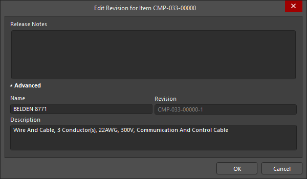 ). After clicking OK and saving the component, the editor will close.
Your new component will be available in the Components panel for placement in your wiring diagram documents. Refer to the Defining the Wiring Diagram page to learn more.
Creation Using the Component Editor (Batch Component Editing Mode)
A component can also be defined using the Component editor in Batch Component Editing mode. When in this mode (which can be accessed by choosing the Tools » Switch to Batch Editor command from the main menus of the Component editor in Single Component Editing mode or by opening multiple components for editing), the harness wiring model can be added as follows:
-
In the Required Models/Parameters region of the editor, click the Add control and select HarnessWiring to specify that the harness wiring model is required by the components being defined.

Add the harness wiring model entry to the list of required models. -
In the Model Links region of the editor, click the Add control and select HarnessWiring, then choose the harness wiring model through the Choose Models dialog that opens. Any number of model links may be added, including links to different revisions of the same model. In this way, add links to the required harness wiring models to be used by components being defined in the editor.

Add links to the required harness wiring models. -
In the component definition region below, click within the HarnessWiring model cell and use the drop-down field to access the pop-up window, which presents a grid of added harness wiring model links. Double-click the required model entry to assign that model to the component definition.

Assign an added model link to a component definition. -
Complete the component definitions with other required data (e.g., parameters, part choices, and datasheets).
-
Save the components to the Workspace by selecting the File » Save to Server command.

Editing a Harness Wiring Model
Harness wiring models can be browsed using the Components panel. Enable visibility of models by clicking the ![]() button at the top of the panel and selecting Models, then selecting the Harness Wirings category.
button at the top of the panel and selecting Models, then selecting the Harness Wirings category.

To edit an existing harness wiring model, right-click its entry in the Components panel and select the Edit command. The temporary editor will open, with the model opened for editing. Make changes as required and save the model to the Workspace.
 ).
).Updating Related Components
When you make a change to a harness wiring model, the moment you save that change into a new revision of the model, any components that use that model will become effectively out of date, still using the previous revision of the model. In most cases, you will no doubt want to re-save those components, with the respective model links updated to use the latest revisions available. To streamline this process, a Workspace, in conjunction with Altium Designer, facilitates the ability to update related components – at the point of re-saving a Workspace model – after having made any modifications to that model through the direct editing feature.
The option to perform this update to the parent components can be found in the Create Revision dialog that appears when saving the modified harness wiring model back to the target Workspace. This option – Update items related to <ModelItemRevision> – is enabled by default.

Accessing the option to update related components referencing the harness wiring model being re-saved.
Once you click OK in the Create Revision dialog, the modified harness wiring model is saved back to the Workspace, and its associated temporary editor is closed. All components referencing that harness wiring model will be re-saved to use its new revision automatically (the next revision of each component is automatically created and saving is performed).