
Object & Layer Transparency
The Object Visibility region of the View Configuration panel can be used to set the transparency of each PCB object. Use the Transparency slide bar to set the percentage or enter the desired percentage directly in the percentage field.
![]()
Altium Designer also provides support for setting the transparency of each object type individually and on a per-layer basis for each layer that can be used in board design. This gives you increased control over the display of objects within the design space. The Object Visibility dialog is used to configure, experiment with, and fine-tune transparency-level settings to suit your needs. The Object Visibility dialog is accessed by clicking the ![]() button at the bottom of the Object Visibility region on the View Options tab of the View Configuration panel.
button at the bottom of the Object Visibility region on the View Options tab of the View Configuration panel.

Options and Controls of the Object Visibility Dialog
Columns/Rows
-
Layers - each individual layer may be selected in the left-hand margin by clicking on the desired layer. The entire row will need to be selected in order to toggle the transparency. Use the drop-down next to the layer's name to hide the layer if desired.
-
Objects - each individual object will be selected by clicking on the desired object. An individual entry can be selected if you'd like to only modify the transparency of this object on a specific layer.
Transparency Controls
- Only show used layers - check this box to only display layers that have been used in the design.
- Transparency for selected - drag this bar to set the desired transparencies for the select object rows or layer columns.
- Percentage - use this box to manually type in the desired transparencies for the selected object rows or layer columns.
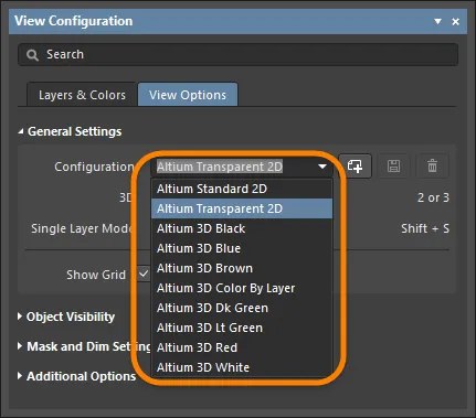
Although the transparency settings can be defined for any 2D view configuration, Altium Designer features a dedicated default 2D view configuration for this very purpose named Altium Transparent 2D. It is identical in all other aspects to the Altium Standard 2D view configuration. Use the Configuration drop-down in the General Settings region on the View Options tab of the View Configuration panel to set the view configuration. The view configurations can be found in the \Templates folder of your installation.
Layers and Objects
The grid of the Object Visibility dialog presents rows that represent each layer and columns that represent each object type. Not only does this allow a unique setting to be defined for a particular object across different layers, but it also allows different objects to have different visibility on a specific layer.
By default, only layers in the current board's layer stack will be shown. To show all layers supported for board design in Altium Designer, disable the Only show used layers option.
The layers themselves are grouped by their functional types:
-
Signal Layers
-
Internal Planes
-
Other Layers
-
Silkscreen Layers
-
Mask Layers
-
Mechanical Layers
Layers that are currently not used in the design have their names and transparency values displayed in gray text. You can still configure the transparencies as required for any unused layers.
When you want to set up a global configuration for transparencies that can be used for any board design, it is a good idea to disable the Only show used layers option then configure the settings for each and every layer. In this way, if additional layers are added to a particular board design, the visibility settings will already be defined and ready for use.
Defining Transparency
To set a value for an object's transparency on a single layer, select the intersecting cell for the required object and layer, then use the Transparency for selected slide bar or enter the desired percentage.
Transparency is set on a percentage scale in 1% increments. 0% is fully visible (solid) and 100% is fully transparent (invisible).
Use the following multi-select controls to select multiple objects then set a common transparency for the selected objects.
- Ctrl+click to select all cells within the same column.
- Shift+click (or Shift+Arrow) to select contiguous cells across multiple columns and/or rows.
- Click&drag to select multiple contiguous cells within the same, single row.
To quickly set the transparency for all object types on a specific layer, click on the layer name to select the entire row then set the desired transparency.
To quickly set the transparency for all objects across multiple contiguous layers, use multi-select controls to first select the required layer cells then set the transparency.
To quickly set the transparency for a specific object type across all layers, click on the object name cell to select the entire column then set the transparency.
Transparency in Action
The following image shows an example of transparency settings. As you can see, in Altium Standard 2D, the polygon pours on the top layer pretty much prevent anything from being seen.
![]()
The image below shows the result of setting up some transparency settings for various objects on different layers as part of the Altium Transparent 2D view configuration. By switching to this view in the design space, the 70% transparency set for polygon pours across layers kicks in, which allows other objects directly beneath to be viewed, almost like viewing an X-ray. By tweaking transparency settings, the resulting view of objects could undoubtedly be made more desirable still. The point is, with fully configurable transparency settings, you have the ability to get your transparent view of the board just the way you like it.
![]()
To get a true view of the mask layers without Multi-Layer objects such as pads and vias getting in the way, increase the transparency of those objects or make them fully (100%) transparent. This can prove very useful if you have undersized your mask openings!