 Altium NEXUS Documentation
...
EOL - Design Objects
PCB Design Objects
Altium NEXUS Documentation
...
EOL - Design Objects
PCB Design Objects
Coverlay Polygon
This document is no longer available beyond version 4. Information can now be found here: Including Coverlay on a Flex Region for version 5
Parent page: PCB Design Objects

An example of a custom coverlay
Summary
A common feature on rigid-flex boards is the selective use of coverlay material. This insulation layer is cut and laminated onto specific areas of the board, and because of this selective use, coverlay is also referred to as bikini coverlay. Coverlay layers are added in the Layer Stack Manager and the shape of coverlay objects can be manipulated in Board Planning Mode, once coverlays have been enabled for that region of the board.
Availability and Placement
Coverlay
Coverlay layers are added in the Layer Stack Manager. To add coverlay layers:
- Enable the Is Flex option for the flex substack.
- Right-click on the appropriate layer(s) and select the Insert layer above (below) » Coverlay command to add coverlays.
- Define the properties of the coverlay, including the Coverlay expansion property.
- Save the layer stack to reflect the changes on the board.
- In Board Planning mode there will now be additional tabs for each coverlay layer added in the stack. Note that the color of the coverlay is defined by the layer color (View Configuration panel), not the color assigned in the Layer Stack Manager.
 into the substack and configure the layer properties in the Layer Stack Manager.")
Add the coverlay layer(s) into the substack and configure the layer properties in the Layer Stack Manager.
Enabling and Viewing the Coverlay
If coverlay layers are added to the substack before that substack is assigned to a Board Region, the coverlay objects will be present when the substack is assigned to a Board Region.
If coverlay layers are added to the substack after that substack has already been assigned to a Board Region, then coverlays must be added to that region. Coverlays can be added in Board Planning mode by selecting the Board Region and then either:
- Right-clicking on the region and selecting the Coverlay Actions » Add Coverlay command, or
- Clicking the Add Coverlay button in the Board Region mode of the Properties panel.

If the Board Region had the substack assigned before the coverlays were added in the LSM, use the right-click command or the panel button to add them to that region.
Editing or Placing Additional Coverlay
Coverlay is automatically added to cover the entire area of the Board Region it was added to, as shown in the image below (in accordance with the Coverlay expansion value defined in the Layer Stack Manager). Behaving like an additional solder mask layer, openings are automatically created for component pads in accordance with the applicable Solder Mask Expansion design rule, or else the settings defined for the Pad if the Solder Mask Expansions setting has been configured to override the design rule.
.")
Openings in the coverlay for the component pads is controlled by the applicable Solder Mask Expansion design rule (which can be overridden by local pad settings).
To edit the coverlay:
- Switch to Board Planning mode.
- Click the appropriate layer tab to make the Coverlay layer the active layer (the Coverlay layers may need to be made visible in the View Configuration panel).
- The automatic coverlay is formed as a polygonal object, it can be selected and reshaped (or deleted) as required.
- User-defined coverlay shapes can also be placed if required, using the Design » Place Coverlay Polygon and Design » Place Coverlay Cutout commands.

A section of custom coverlay has been placed and a cutout is about to be defined in it.
Coverlay Polygon
Coverlay Polygons can be placed when a PCB editor is in Board Planning Mode. Select the Design » Place Coverlay Polygon command from the main menus.
Coverlay Polygon Placement Modes
- While placing a polygon there are five available corner modes, four of which also have corner direction sub-modes. During placement:
- Press Shift+Spacebar to cycle through the five available corner modes.
- Press Spacebar to toggle between the two corner direction sub-modes.
- When in either of the arc corner modes, hold the arrow keys to shrink or grow the arc. Hold the Shift key as you press to accelerate arc resizing.
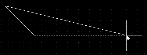
- Press the 1 shortcut key to toggle between placing two edges per click or one edge per click. In the second mode, the dashed edge is referred to as the look-ahead segment (as shown in the last image in the set below).
- Press the Backspace key to remove the last vertex.

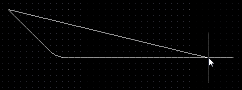
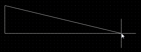
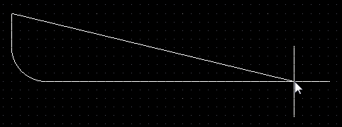
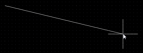
Press Shift+Spacebar to cycle through the five available corner modes, press the 1 shortcut to toggle placement between two edges or one edge.
Graphical Editing
This method of editing allows you to select a placed coverlay polygon object directly in the design space and graphically change its size, shape or location.
Click once on a coverlay polygon object to select it, which puts it into edit mode. The outer shape of the coverlay polygon object is defined by a series of edges, where each edge is represented by an end vertex at each end, shown as a solid white square, and a center vertex in the middle is shown as a hollow white square. Each end vertex represents the location where two edges meet.
 A selected Coverlay Polygon
- Click and drag A to move the applicable end vertex.
- Click and drag B to move the applicable center vertex, effectively creating a new end vertex and splitting the original edge into two.
- Click anywhere along an edge away from editing handles then drag to slide that edge.
- Ctrl+click anywhere along an edge away from editing handles to insert a new end vertex.
- Click and hold on an end vertex then press Delete to remove that vertex.
- Click anywhere on the coverlay polygon away from editing handles then drag to reposition it. While dragging, the coverlay polygon can be rotated or mirrored:
- Press the Spacebar to rotate the coverlay polygon counterclockwise or Shift+Spacebar for clockwise rotation. The Rotation Step size is defined on the PCB Editor – General page of the Preferences dialog.
- Press the X or Y keys to mirror the coverlay polygon along the X-axis or Y-axis.