
Rigid-Flex
PCB Design
Make flex and rigid-flex designs
in Altium Designer’s unified environment,
with no limitations or additional licensing required
Powerful Tools That Can Handle
Any Design Complexity
Create Any Rigid-Flex PCB Structure
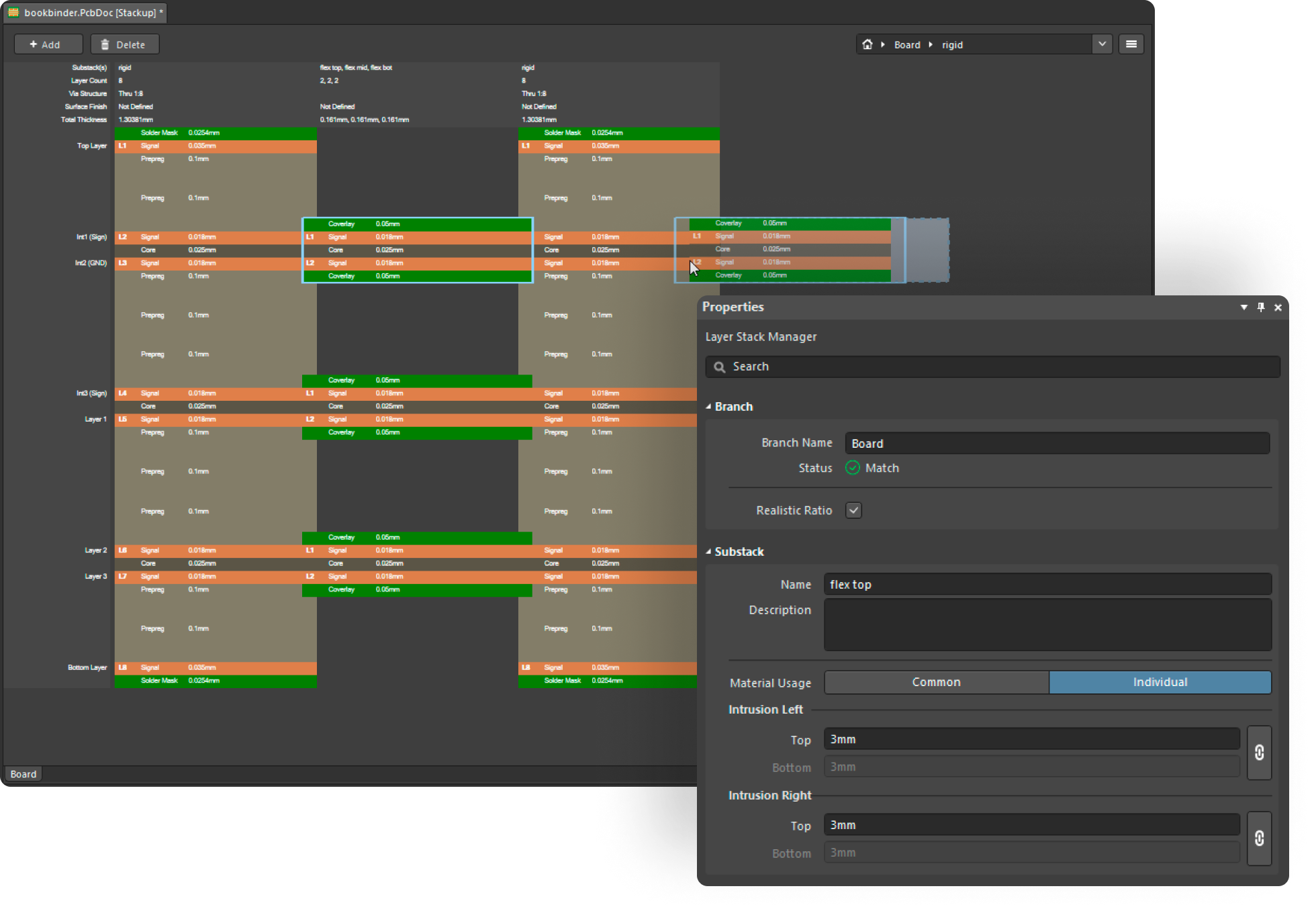
Rigid-Flex circuit boards can have a variety of structures, whether that’s a simple one where two rigid parts are connected by a single flex layer, or a complex “bookbinding” design with multiple branches and inserts. The special ability to create separate overlapping flexible parts and flexible parts inside cutouts in the rigid part ensures that whatever solution you require, your most ambitious designs can be realized in Altium Designer.
Flexible PCB Stackups Manipulation for Design Precision
With Altium Designer, adding stiffeners, adhesives, and coverlays to your PCBs is straightforward, ensuring everything is clear for the manufacturer. It makes designing complex stackups simpler, helping both new and experienced users get it right. This tool streamlines your design process, making complex tasks more manageable and ensuring high-quality outcomes. What's more, it allows you to effectively manage rigid flex PCB costs, contributing to more budget-friendly projects.
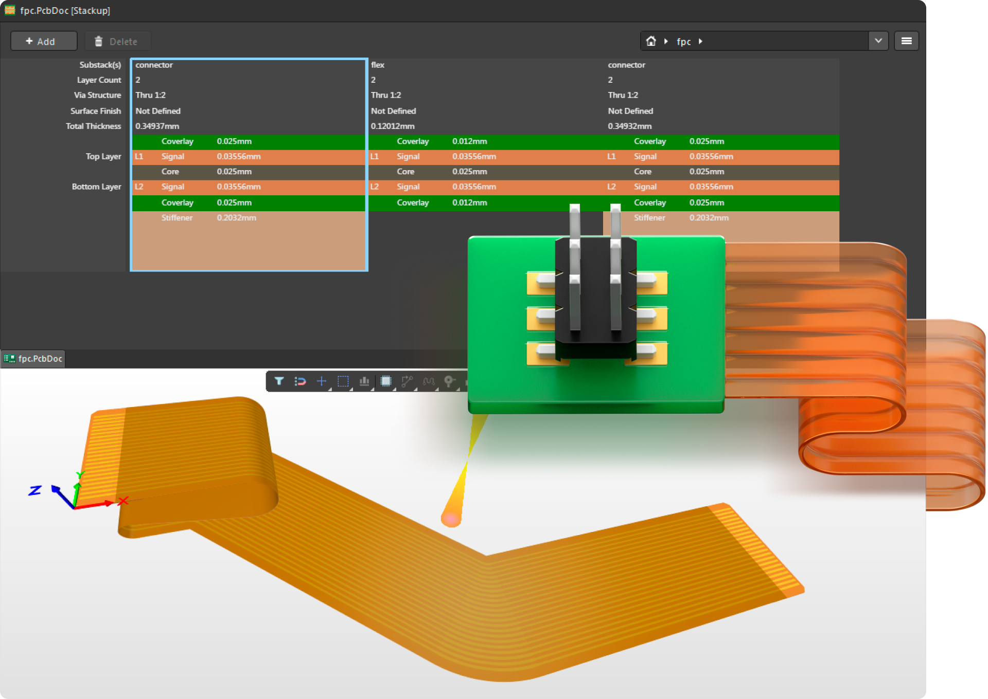
Get a Clear Picture of Your Stackup at a Glance
Get a clear view of your rigid-flex PCBs with high-quality visualizations in Altium Designer. Its Layer Stack Manager makes it easy to see and understand what each layer and flex section does. This means you can spend more time designing your PCB and less on figuring out the parts' details!
Implement Your Most Ambitious Designs
in Altium Designer Today!
Key Capabilities
Add Stiffeners, Adhesives and Coverlays
Rigid-Flex PCB structures always include an adhesive, coverlay, and in some cases a stiffener if there is an edge connector on a flex part. All of these can be added to your PCB stackup and conductive layers or dielectrics.

Create Regions For a Specific Substack
Rigid-Flex PCBs consist of many parts, and each has its own unique structure. With the help of simple and convenient tools in Altium Designer, you can easily assign the position of a particular substack in your PCB with a region.

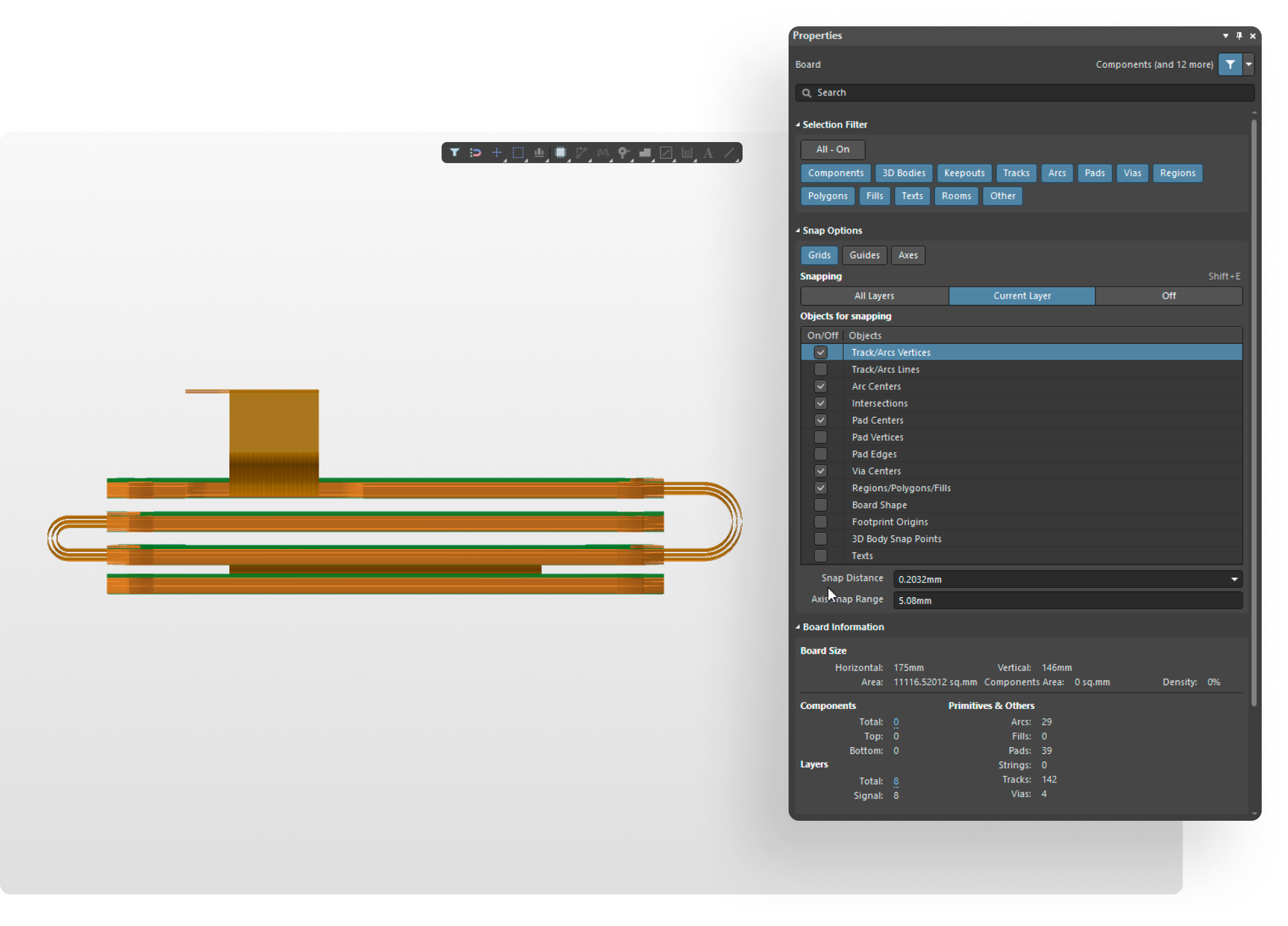
Make Multiple Overlapping Flexible Parts
If your rigid-flex PCB needs to connect to multiple devices at once you can easily design a compact construction. Quickly create different flexible parts that extend from one area of a rigid region to another in Altium Designer.

Define Flexible Parts Inside Rigid Cutouts
With Altium Designer you can assign any location on a rigid PCB to output a flex part. It can be on any side or even a cutout on the board.

Create Bend Lines On Flexible Parts
With just two clicks you can set the exact location for bend lines and specify the radius. Defining all the bending parameters in Altium Designer will ensure that your PCB fits into its enclosure while providing helpful instructions for your manufacturer.

Verify Your PCB Stack Design
Rigid-Flex PCB structures must be designed to follow certain rules. The intelligent system integrated in the Layer Stack Manager will check your stack, indicate problem areas, and make recommendations on how to fix issues.

Freely Manipulate Substacks
Altium Designer offers a variety of manipulation tools for substacks that are necessary for your initial design stages. You can delete, copy, move, and edit substacks as needed.

Visualize Your Design in 3D
Look at your design from all sides, and also manipulate the bend angle of any flex part. Altium Designer also allows you to save your PCB as a 3D model, 3D PDF file, or an mp4 video that shows the animated bending of flexible parts.

Design a Rigid-Flex PCB With an MCAD Engineer
Use MCAD CoDesigner to create and share a rigid-flex PCB with a mechanical engineer. Dimensions, locations of flexible parts, and bend lines can all be defined in an MCAD environment. All you have to do is design the PCB and share your schematic parameters.


Unlock Your Full
Potential with Altium
Professional Training
Enhance your design skills, streamline your workflow,
and deliver high-quality results faster with expert-led
training tailored to Altium’s powerful tools.
Testimonials
Start your free trial today!
Get Immediate, Full-Feature Access:
Explore More Features
 Wire Bonding
  Workflow Process
  HDI Design
 Constraint Manager
 True 3D-MID Design
  PLM Integration
  Harness Design
 Reuse Your Best Solutions
  Variant Manager
 Manufacturer Part Search
 Layer Stackup Design
 Intuitive Multi-Board System Design
  Rigid-Flex PCB Design
 Unparalleled Schematic Capture
  Supply Chain Intelligence
  Real-Time BOM Management with ActiveBOM®
  Best in Class Interactive Routing
  Professional PCB Drawings in Minutes
 Certainty for Every Decision with SPICE Simulation
 High-Speed PCB Design