, documents and projects to add detail information to the design.") Parameters are used for objects (a component is shown in the above image), documents and projects to add detail information to the design.
Parameters are used for objects (a component is shown in the above image), documents and projects to add detail information to the design.
Summary
Parameters are general purpose text strings that are child objects of a parent object. They identify and add additional information to that parent object and are accessed directly in the Properties panel when selected in a schematic sheet.
Schematic components, for example, make extensive use of parameters. They are used to define the Sheet Name and the Comment, as well as the general purpose data strings that can be added to a component to fully define it. General purpose (User) component parameters can be used for a variety of functions including; component details and ratings, supplier information, library references, and datasheet links.
Parameters also can be defined at the schematic sheet (document) and project levels. Document-level parameters are used for defining fields such as the document title and number, while project-level parameters are ideal for defining fields such as the designer or the project name.
Availability
Parameters are added or automatically included as a property of the parent object and are not placed independently like a Text String. The types of available parameters can be broadly grouped as System and User parameters, where the latter is manually added.
Identifier and System Parameters
A range of key system parameters is automatically included with objects placed in a schematic. These provide the base object information that is used by the system to distinguish the parent object's name, type and data source.
The inherent system parameters for objects include, but are not limited to, the Comment, Description and Design Item ID (Library Reference) properties.
Object system parameters are accessible in the General section of the Properties panel (under the General tab) when a parent object is selected. When visible and selected in the design space, an individual parameter is accessible via the associated mode of the Properties panel as outlined below.

 Left: Component system parameters in the Properties panel. Right: An individual system parameter in the Properties panel.
Several system parameters cannot be made visible (and be selected) on a schematic sheet, and are therefore not available to the Parameters mode of the Properties panel. For component objects, these are Description, Design Item ID, Footprint, model references and so on. Other system parameters that are not directly accessible in a schematic include Document (Sheet) and Project parameters.
User Parameters
Parameters are added as a property of the parent object and are not placed independently like a Text String. Parameters can be added to any of the following design objects:
- Component – add user-defined parameters in the Parameters tab of the Properties panel when a Component (Part) object is selected, or during component definition in the Schematic Library editor. System parameters such as Designator and Comment are always present for a Component object, as outline above. The Properties panel is accessed by double-clicking on an object, or by right-clicking on an object and choosing Properties from the context menu. If the Properties panel is already active, select an object in the design space.
- Part – in the Parameters region of the Properties panel when a Part object is selected.
- Pin - on the Parameters tab of the Properties panel when a Pin object is selected within a .SchLib file.
- Port – on the Parameters tab of the Properties panel when a Port object is selected.
- Sheet Symbol – on the Parameters tab of the Properties panel when a Sheet Symbol object is selected.
- Document – on the Parameters tab of the Properties panel when in Document Options mode (deselect all schematic objects or click in free space on the document sheet). A number of default parameters are automatically included in a new schematic sheet, as determined by the applied/default sheet template.
- Project - in the Project Options dialog (Project » Project Options). Project-level parameters are listed and added on the Parameters tab of the dialog.
While placing an object (Component, Sheet Symbol, etc.,), press
Tab to pause the placement and access the parent object mode of the
Propertiespanel, from where parameters can be added or modified on the fly. Click the design space pause button overlay (

) to resume placement.
User parameters are available under the Parameters tab of the Properties panel, or modal dialog, when the parent object is selected – parameters can be both added and edited. The exceptions are Project parameters (via the Project Options dialog) and Component Pin parameters (via the Pin Properties, or the modal-view of the Pin dialog). When visible and selected in the design space, an individual parameter is accessible via the associated mode of the Properties panel, or modal dialog, as outlined below.
. Right: An individual system parameter in the Properties panel.")
 Left: Component user parameters in the Properties panel (Parameters tab). Right: An individual system parameter in the Properties panel.
Parameters that are added to a parent object during its placement (see above) will become the default parameters for further placements of that parent object unless the
Permanent option on the
Schematic – Default Primitives page of the
Preferences dialog is enabled for that object.
When this option is enabled, parameters added to the object being placed will be also added to subsequent objects placed during the same placement session, but not to any following placement sessions for that object.
Graphical Editing
Visible parameter strings can be edited graphically, directly in the design space.
Click and drag a parameter to reposition it. To edit the parameter string in place:
- Drag your mouse cursor around the parameter object while keeping the mouse button pushed down.
- Once selected, the object will be highlight by a green border.
- Select Enter to begin editing the text.
- Once editing is complete, press Enter again or click away from the string to exit in-place editing mode.
 Select the entire string to type over it.") A parameter string can be selected and edited directly in the design space. (Right) Select the entire string to type over it.
A parameter string can be selected and edited directly in the design space. (Right) Select the entire string to type over it.
Parameters that are visible and selectable in the design space may be dragged to a new location and rotated during the process. Click and drag the parameter string, use the Spacebar and Shift+Spacebar keys to rotate it in 90° steps, and then click to confirm its new position/orientation.
See Parameter String Positioning below for information on component parameter Autopositioning and related Properties panel options.
Locked Parameters
A parameter that is the child of a Component Part can be locked, where its Name and Value strings are made un-editable. This can be done by:
- toggling the Lock icon (
 ) associated with its entry under the Parameters tab in the Properties panel or modal dialog for its parent object, or
- checking the Lock Parameter option in the Properties panel when the parameter is directly selected in the design space.
Once locked, the parameter string cannot be edited in the Properties panel, modal dialog (under the Parameters tab for the parent object), or in the design space using in-place editing.
Component Parameters
Component parameters, the most obvious and frequently used Schematic parameters, include additional sets of dedicated parameters and features that expand the ability to define component objects.
Defining Parameters in the Schematic Library
Prior to placement in a schematic, the child parameters of a parent component object can be defined in the component library source. Using the Properties panel in the same manner as when working with parameters in the Schematic Editor, the panel is used to edit and add parameters to a component entry in the Schematic Library Editor.
With a schematic component library document open, select a component entry in the SCH Library panel (View » Panels » SCH Library) to access its parameter properties in the Properties panel.
 Access the properties of a library component by selecting its entry in the SCH Library panel.
A library component's Designator and Comment are not visible in the Schematic Library editor design space by default but can be enabled by checking the Show Comment/Designator option in the Library Options mode of the Properties panel (Tools » Document Options) – available when no objects are selected in the design space.
Parameters that are owned by a library component are defined and edited by the same process applied to placed schematic components. The Tab key may be used to create or edit parameters on the fly, while an object is being placed in the editor design space. Parameters are accessed via the Properties panel or modal dialog, where the core system parameters are available under the panel's General tab, and user parameters are added/edited under the panel's Parameters drop-down.
To add a parameter to a component pin, for example, select the
Pin object in the design space then the
Parameters drop-down in the
Properties panel or modal dialog. Click the
Add button to insert a new parameter Name/Value pair in the list. Parameters that are associated with the entire component are added as described above.
The Designator Parameter
In the Library Editor, a component Designator parameter is typically given a suitable prefix followed by a question mark. When the component is placed in a schematic from the library, the question mark is detected by the Schematic Editor's Annotation tool and replaced with a suitable numeric suffix during project annotation.
The Schematic Editor also includes a simple auto-increment feature for the designator that can be used during the placement of multiple instances of the same part. To use this, press Tab while the first component is floating on the cursor to pause the placement, and then enter a suitable designator in the Properties panel; for example R1. Subsequent components will then be designated R2, R3, etc.
When placing multi-part components and the initial designator is assigned in this way, a part suffix will automatically be added, for example U3A, U3B, etc. If the initial designator is not assigned, all parts will have the same suffix – this can be resolved by the Schematic Editor's Annotation feature. The part suffix can be alpha or numeric, as specified by the Alpha Numeric Suffix option in the Schematic - General page of the Preferences dialog.
Parameter String Positioning
The default behavior of a component parameter string is to autoposition it (maintain orientation) when a component is rotated during or after placement. If this behavior is not required, turn off the Autoposition option for that component parameter entry under the Parameters tab in the Properties panel – select the parameter in the list and click the Other link for access to the option.
Note that during component placement the
Spacebar and
Shift+Spacebar keys are used for rotation. A placed component object is rotated via the
Rotation menu in the
Location section of the
Properties panel, or by selecting the component and pressing
Ctrl+Spacebar or
Ctrl+Shift+Spacebar.
Click and drag a visible parameter to manually reposition that parameter on the schematic – the standard orientation shortcut keys (Spacebar, Shift+Spacebar) will apply. If the Autoposition option is disabled for that parameter and the Mark Manual Parameters option is enabled in the Schematic - Graphical Editing page of the Preferences dialog, manually moved parameters will be identified by a dot on the lower left corner of their selection box.
Special Purpose Component Parameters
Special purpose component parameters are available for linking to related URL targets or file-based documentation. For a selected component, these are added in the Links section of the Properties panel, or under the Parameters tab for dedicated Help links that are activated via the F1 key.
Link Parameters
The Links feature enables the definition and presentation of named links to any number of reference URLs or documents.
To add a reference link for a component, select it in the design space, click the  drop-down button in the Links section of the Properties panel, and then enter the link Name and its Value (target URL or file path). The link is then accessible by right-clicking on the component in the design space and selecting the link Name from the References sub-menu.

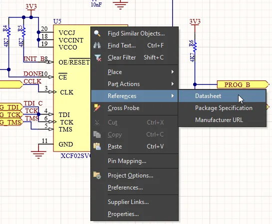
The component links, as presented in the panel and design space, are internally based on Name/Value pairs in the format of ComponentLinknDescription/ComponentLinknURL (where n is number of the link in the list, based on the order of creation). See the Parameter Table Editor entry for that component to see more detail.
The HelpURL Parameter
Not unlike the Link parameter, the HelpURL parameter allows the definition of a link from a component to an external document, such as a PDF, or web page URL. When added as a component parameter, this link is activated when the F1 key is pressed over the component on the schematic sheet, or when that component is selected in the Libraries panel. Note that this action will override the normal F1 key feature, which links to the relevant page in the Altium online documentation.
The Help link is added as a user parameter under the Parameters tab of Properties panel, when a component is selected in the design space. Click the drop-down button to create a new parameter in the list, enter HelpURL as the parameter Name and then the target path/URL as the parameter Value.

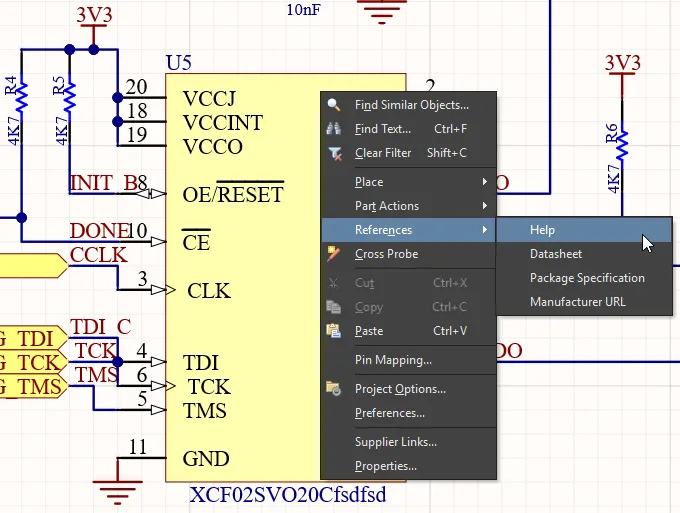
When specifying the value for the parameter, this can be a URL, an absolute path to a document or just the document name. When F1 is pressed with the cursor hovering over the placed component object, or the References » Help option is used from the right-click menu, a search for the Help reference is conducted as follows:
- If a path is specified, this location is searched first.
- If the document cannot be found at this location, or if no path is specified, the
\Help folder of the software installation is searched.
- If the target is a URL, the web page will be opened in the software's internal browser or an external browser, depending on the state of the Open internet links in external Web browser option on the System - View page of the Preferences dialog.
Indirection - A Parameter as a String Value
Most component parameters can be displayed on a schematic sheet by checking their Visible option (where available) in the Properties panel ( ). Identifier and system parameters are available under the panel’s General tab, and user parameters are accessed under the panel’s Parameters tab.
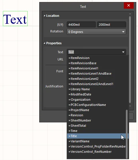
Other parameters however, such as Document and Project parameters, cannot be directly displayed on the schematic sheet but may be inserted in a standard Text object using a technique known as String Indirection. Indirection is where the Value entry for a string object is the name of an available parameter (such as a Document or Project parameter) preceded by an equals sign – for example; =Title.
The software automatically detects such strings and checks for an available parameter Name that matches the Value entry of the placed Text object. The example of Title is found as a document parameter, causing the Text string to interpret and display the Title parameter Value – for example; MyDocument. A parameter Name may be indirected to a selected text string Value by in-place editing (typing =Title into it), or as a more informative approach, by using the Text drop down menu in the Properties panel to select from the available parameter strings.
Special Strings
Parameter strings that are available as indirected strings (see above) are known as Special Strings. The Value presented by these strings is actively inferred from templates or system and source data, so for example the special string =Time will detect and show the current system time, and =DocumentName will show the current schematic document file name (say, MySchematic.SchDoc).
There is a large number of predefined special strings available, which are listed below. Any user-defined document or project parameter can also be thought of as a special string and be indirected to a Text String on the schematic sheet.
Indirected strings are always interpreted and displayed during output generation, such as printing the schematic sheets. Many are also interpreted and displayed directly on-screen.
Special Strings are used to define fields in a title block, where the string indirection feature will ensure the correct information for the active schematic is extracted from the document parameters and displayed accordingly.
Parameters have a hierarchy, which means you can create a parameter with the same name at different levels of the project, each having different values. For a component parameter, Altium NEXUS resolves this in the following way:
- Component parameter (highest priority)
- Variant
- Schematic document
- Sheet Symbol (to see the value of the parameter of the sheet symbol above, select a compiled tab at the bottom of the design space)
- Project
Schematic Predefined Special Strings
The following are the predefined special strings available for use on a schematic document. The majority of these link to default parameter information defined for the active document on the Parameters tab of the Properties panel, when in Document Options mode (no objects selected). Any special strings available at a project level can be viewed/added on the Parameters tab of the Project Options dialog.
=Address1 – displays the value specified for the default document-level parameter Address1.=Address2 – displays the value specified for the default document-level parameter Address2.=Address3 – displays the value specified for the default document-level parameter Address3.=Address4 – displays the value specified for the default document-level parameter Address4.- =Application_BuildNumber – displays the version and build for the current Altium software installation.
=ApprovedBy – displays the value specified for the default document-level parameter ApprovedBy.=Author – displays the value specified for the default document-level parameter Author.=CheckedBy – displays the value specified for the default document-level parameter CheckedBy.=CompanyName – displays the value specified for the default document-level parameter CompanyName.=ConfigurationParameters - displays the value specified for the default document-level parameter ConfirguationParameters.=CurrentDate – the current date, automatically calculated from the user's system settings and in the format dd/mm/yyyy, updated upon editing the schematic or on refresh/redraw. Example: 10/12/2017.=CurrentTime – the current time, automatically calculated from the user's system settings and in the format h:mm:ss AM/PM, updated upon editing the schematic or on refresh/redraw. Example: 2:39:47 PM.=Date – used to display static date information. Displays the value specified for the default document-level parameter Date. Unlike the =CurrentDate special string, which is automatically calculated and presented in a set format, the user can enter static date information in any format they prefer.=DocumentFullPathAndName – used to display the full path and name of the document into which the string is placed. Example: C:\MyTestDesign\PSU.SchDoc.=DocumentName – used to display the schematic's file name only (without the file path). Example: PSU.SchDoc.=DocumentNumber – displays the value specified for the default document-level parameter DocumentNumber. The source parameter can also be updated through the Sheet Numbering for Project dialog when using the Tools » Annotation » Number Schematic Sheets command.=DrawnBy – displays the value specified for the default document-level parameter DrawnBy.=Engineer – displays the value specified for the default document-level parameter Engineer.=ImagePath – displays the value specified for the default document-level parameter ImagePath.- =IsUserConfigurable - user can configure.
=Item – the Item that the generated data relates to (e.g., D-810-2000). The data will be used to build that Item.=ItemAndRevision – the Item and specific revision of that Item to which the generated data relates in the format <Item ID>-<Revision ID> (e.g. D-810-2000-01.A.1). The data will be used to build that specific revision of that particular Item.=ItemRevision – the specific revision of the Item to which the generated data relates (e.g., 01.A.1). The data is stored in that Item Revision within the target server.=ItemRevisionBase – the Base Level portion of an Item Revision's naming scheme (e.g., 1).=ItemRevisionLeve1 – the Level 1 portion of an Item Revision's naming scheme (e.g., A).=ItemRevisionLeve1AndBase – the Level 1 and Base Level portions of an Item Revision's naming scheme (e.g., A.1).=ItemRevisionLevel2 – the Level 2 portion of an Item Revision's naming scheme (e.g., 01).=ItemRevisionLevel2AndLevel1 – the Level 2 and Level 1 portions of an Item Revision's naming scheme (e.g., 01.A).- =LibraryName - displays the actual name of the schematic library file. (e.g., SpiritLevel_2E.SchLib)
=ModifiedDate – the modified date stamp of the schematic, automatically populated. Example: 10/12/2015.=Organization – displays the value specified for the default document-level parameter Organization.=PCBConfigurationName – the name of the data set from which the output has been generated as defined in the Release view (Project Releaser).=Project – displays the name of the project (excluding extension). =ProjectName – displays the actual name of the project (including extension). For example, for a project with filename MyPCB.PrjPcb, this special string will display MyPCB.PrjPcb.- =ProjectRev - displays the project revision.
=Revision – displays the value specified for the default document-level parameter Revision.=SheetNumber – the sheet number of the current schematic. This value is calculated when using the Tools » Annotation » Number Schematic Sheets command. The assigned sheet number, in the Sheet Numbering for Project dialog, will be entered into the value for the default document-level parameter SheetNumber. The special string when used on the Editor tab view of the schematic sheet will source its information from here.=SheetTotal – the sheet total for the project. This value is calculated when using the Tools » Number Schematic Sheets command. The sheet total, in the Sheet Numbering for Project dialog, will be entered into the value for the default document-level parameter SheetTotal. The special string when used on the Editor tab view of the schematic sheet will source its information from here.=Time – used to display static time information. Displays the value specified for the default document-level parameter Time. Unlike the =CurrentTime special string, which is automatically calculated and presented in a set format, the user can enter static time information in any format.=Title – displays the value specified for the default document-level parameter Title.- =VariantName - displays the variant from which output has been generated. This follows the entry for the current variant. If the base design is used to generate the output, the value will simply be [No Variations].
=VersionControl_ProjFolderRevNumber – the current revision number of the Project, which is incremented whenever a full commit of the project (i.e. including the project file) is performed. Version control must be used for this string to contain any information.=VersionControl_RevNumber – the current revision number of the document. Version control must be used for this string to contain any information.
Note that the full list of special strings available in the Text drop-down menu in the Properties panel (when a text object is selected) will also include any derived from user-defined document-level and project-level parameters.
Special Strings for Use with Component Parameters
Several additional special strings (or special interpretations of existing ones) are available when defining component parameters. In each case, the special string is entered as the value for a parameter.
=CurrentFootprint – displays the name of the currently assigned footprint for the component as defined in the Models region of the Properties panel (General tab).=Comment – displays the value appearing in the component's Comment field as defined in the Properties region of the Properties panel (General tab).=Description – displays the value appearing in the component's Description field as defined in the Properties region of the Properties panel (General tab).=[ParameterName] – displays the value defined for a specified component parameter. Enter the actual name of a component parameter as the special string name. For example, for a component parameter named PowerRating, enter =PowerRating. This approach can be used to display a component parameter such as Description by creating a user parameter (under the Parameters tab of the Properties panel) with a value of =Description, and then enabling that parameter's visibility in the schematic.
