Workspace 内のコンテンツは、次のようないくつかの方法でナビゲートできます。
また、関連する
Show in Explorer または
Show in Serverコマンドを通じて、特定の Item について
Explorerパネルへ直接アクセスできる各種箇所にも遭遇します。たとえば、回路図または PCB ドキュメントに配置された Workspace ライブラリコンポーネント上で右クリックし、コンテキストメニューからそれぞれ
Part Actions » Show <ItemID-RevisionID> [<ItemName>] in Server または
Component Actions » Show <ItemID-RevisionID> [<ItemName>] in Server コマンドを選択すると、対応する Component Item の特定リビジョンが選択/表示された状態で
Explorerパネルが開きます。
フォルダ構造全体は、パネルの右クリックメニューにある対応コマンド(Expand AllおよびCollapse All)で展開/折りたたみできます。特定のフォルダとその配下のサブフォルダをすべて完全に展開するには、そのフォルダを右クリックしてExpand Subtreeコマンドを使用します。
選択したフォルダの内容は、パネルの Items 領域に表示されます。
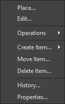
Commands for the Items Region
-
Place – 現在選択している Item-Revision のインスタンスを、配置がサポートされている場所に配置するために使用します。たとえば、コンポーネントや管理シートをアクティブな回路図シートへ配置する場合などです。コンポーネントのシンボル、または管理シートのシンボルがカーソルに追従して表示され、配置できる状態になります。
-
Edit – コンポーネント、管理シート、テンプレートなどの Item を、関連付けられたエディタで開くために使用します。編集後は、Item の新しいリビジョンとして Workspace に保存し戻されます。
-
Upload – Create New Revision dialogを介して、構成オブジェクト(例:Managed Schematic Sheet への回路図ドキュメント、Output Job Template への OutJob ファイル)を Item にアップロードするために使用します。
-
Operations – 次のコマンドを含むサブメニューにアクセスするために使用します。
-
Add to Content Cart – Content Cart dialogを使用して、現在選択している Item を Content Cart に追加するために使用します。
-
Download – Browse for Folder dialog を使用して、現在選択している Item をダウンロードし、別の場所に保存するために使用します。
-
Change state – Batch State Change dialogを開き、現在選択している Item Revision の状態を変更するために使用します。
-
Make a copy – 現在選択している Item-Revision をコピーするために使用します。コピーされた Item は、関連付けられたエディタ(例:コンポーネントをクローンする場合はComponent Editor)で編集用に開かれます。
Project View(Classic View ではなく)モードの場合、Project のコピー操作は、(右上の) ボタンメニューのMake a copy コマンドから実行します。コピーされた Project は、Copy Project dialog で設定用に開かれます。
-
Change component type – Choose component type dialog にアクセスし、選択したコンポーネントのComponentTypeパラメータを別のタイプに設定するために使用します。
-
Export Grid – Select columns for data export dialog を開き、エクスポートする列データを指定するために使用します。エクスポートされるセミコロン区切りの CSV ファイルには、現在のリストのグリッドビューにあるすべての Item のデータが含まれます。
-
Create Item – 現在のフォルダ(Components、Templates、Managed Schematic Sheets など)に一致するタイプの新しいコンテンツ Item を追加し、関連付けられたエディタで開くために使用します。別タイプの Item を作成するには、Other Item Typeサブオプションを選択し、Create New Item dialogのContent Typeメニューから別のタイプを選択します。
-
Move Item – Move Item dialog にアクセスし、Item の新しい配置先を決定するために使用します。
Note:Component エントリを別の Components Folder に移動しても、Components panelでどのCategoryの下に一覧表示されるかは変わりません。これは、ComponentsパネルでコンポーネントがどのCategoryの下に表示されるかは、そのComponent Typeパラメータで定義され、格納されている Workspace フォルダとは無関係だからです。
コンポーネントのタイプをその場で指定/変更するには、Explorerパネル内の該当エントリを右クリックし、コンテキストメニューからOperations » Change Component Typeオプションを選択してChoose component type dialog を開きます。
-
Delete Item – Item を削除するために使用します。
-
History – 現在選択している Item の詳細ビューにアクセスするために使用します。詳細ビューはソフトウェア内で新しいタブとして開きます。Item Viewでは、特定 Item の Revision および Lifecycle 履歴を非常に詳細に確認でき、さらにその Item を構成するすべての要素も表示されます。このビューにはタイムラインも含まれます。タイムラインを使用して、その Item の Revision レベルまたは Lifecycle State に対して行われた変更の正確な日時と、変更を行ったユーザーを確認できます。
-
Properties – View Item Properties dialog にアクセスし、現在選択している Item のプロパティを表示するために使用します。その Item のリビジョンがまだリリースされていない場合は、プロパティを変更できます。
-
Navigate To <item> – Item ID列から、選択した Item のプレビューをExplorerパネルで開くために使用します。
Workspace 内の各 Item リビジョンについて、Explorerパネルでは、該当する場合にそのリビジョンのさまざまな側面を参照できます。これは、パネル下部のタブを使用して、そのリビジョンに対する 1 つ以上のビューを切り替えることで行います。
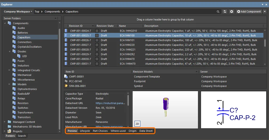
デフォルトレベルのビューはPreviewです。追加のタブをクリックすると、さらに情報を表示できます(利用可能なタブは、現在選択している Item の種類によって異なります)。
-
Preview – 選択した Item の複合的な表示を確認します。ドキュメントやモデルのグラフィック表現、パラメータデータ、関連するサブ Item などが含まれます。このビューは、Item の種類や、Components と Projects に対して Classic または interpreted の表示モード(上記参照)が選択されているかどうかに応じて自動的に設定されます。
-
Lifecycle – Item のリビジョンレベルとLifecycleの状態変更を確認します。Lifecycle は、Item タイプに割り当てられた状態に沿って進められます。たとえば、コンポーネントの場合は Component Lifecycle の状態(Draft、Prototype など)です。
-
Children – Item のサブ要素を表示します。たとえば、リリース済みプロジェクトの Fabrication パッケージ(FAB-<project name>)に含まれる生成済み製造ドキュメント(Gerber、NC Drill など)や、Managed Schematic Sheet で使用されている回路図ドキュメントとコンポーネントなどです。
-
Part Choices – コンポーネントに割り当てられたPart Choices(メーカー部品エントリと、それに関連付けられたサプライヤデータ)を表示または追加します。
Workspace でPart Choice Revision Control機能が有効になっている場合、Part Choices 側面ビューは Part Choices の表示にのみ使用できます。コンポーネントの Part Choices を変更するには、編集用に開いて次のリビジョンとして保存する必要があります。
-
Where-used – 選択した Item リビジョンが、別の Workspace Item でどこに使用されているかを表示します。たとえば、現在選択しているコンポーネントを使用しているプロジェクトなどです。
Workspace プロジェクトにおけるコンポーネントの使用状況は、特定のコンポーネントリビジョンのレベルで追跡されます。Explorerパネルでコンポーネントリビジョンを参照しているとき、Where-used側面ビューのタブには、この特定リビジョンが使用されているプロジェクトのエントリが強調表示されます。使用されていない場合、プロジェクトのエントリは薄く表示されます。
-
Origin – Item の入手元(例:Altium のクラウドリソースから取得した Component)を表示します。可能な場合は、ソース Item の詳細がすべて表示されます。
-
Data Sheet – 選択したコンポーネントとともに保存されている、ファイルベースのdatasheetsを表示または追加します。
Preview側面ビューのタブで子 Item のエントリをダブルクリックするか、ChildrenまたはWhere-used側面ビューのタブで Item エントリをダブルクリックすると、その Item が存在する該当 Workspace 内のその Item へ移動します。

関連するビューを使用して、Item リビジョンのさまざまな側面を参照します。
クリック可能な URL
Workspace の使い勝手をさらに向上させるため、Explorerパネルはクリック可能な URL をサポートしています。この機能は、次のような関連領域で利用できます。
-
URL が値として設定されているコンポーネントパラメータをクリックし、外部 Web ブラウザで対象ページを開きます。
- コンポーネントのサプライチェーンデータ内のURLをクリックすると、外部Webブラウザでリンク先ページが開きます。
-
Released Documents領域内のドキュメントをクリックすると(PCB Fabrication Data Item、PCB Assembly Data Item、またはPCB Project Design Itemのリビジョンに対するPreviewアスペクトビュータブから)、そのドキュメントを開くことができます。
コンポーネントのパラメータおよびプロジェクト関連アイテムのReleased Documentsについては、Altium Designer内でアイテムの詳細を表示している場合にも、この機能を利用できます。このビューにアクセスするには、Explorerパネルでアイテムのエントリを右クリックし、コンテキストメニューからHistoryを選択します。
Clickable Component Parameter URLs
Workspace内のリリース済みコンポーネントでは、Previewアスペクトビュータブにそのコンポーネントのパラメータ用の領域が表示されます。値がURLになっているパラメータ(データシート、パッケージ仕様、メーカーWebサイトなど)の場合、そのURLをクリックすると外部Webブラウザで開きます。
この種のパラメータ値は、URLリンク(http://で始まるもの、または単にwww.のもの)、FTPリンク、共有ネットワークフォルダへのリンク、またはローカルフォルダへのリンクにできます。
リンク先がPDFドキュメントの場合、そのドキュメントはブラウザ内で開くか、外部PDFリーダーで開くかは、ブラウザに設定されたオプションに従います。

Explorerパネル内のComponent Itemに対するPreviewアスペクトビュータブでの、クリック可能なパラメータURLの例。
Clickable Supply Chain URLs
Workspace内の各リリース済みコンポーネントには、Part Choicesの形でサプライチェーンデータを定義できます。これらはPart Choicesアスペクトビュータブに表示されます。実際のサプライチェーンインテリジェンスは、WorkspaceのローカルPart Catalogおよび該当するPart Sourceから取得されます。Part Sourceは、Altium Parts Providerの集約パーツデータベース(有効化されたサプライヤからパーツを取得するためにインターフェースするもの)か、リンクされたローカルパーツデータベース(Custom Database Parts Providerとして構成されたPart Sourceで、Workspaceの種類によってはサポートされます)のいずれかです。各Part Choiceに関連付けられたクリック可能なURLは次のとおりです。
-
Manufacturer NameおよびManufacturer Part Number – メーカーサイトへのクリック可能なリンクで、そのメーカー品番の詳細情報を表示します。
-
サプライヤ品番(SPNタイル内)– サプライヤサイト上の該当部品へのクリック可能なリンクです。
URLをクリックすると外部ブラウザで開きます。

Workspace内のコンポーネントに定義されたPart Choiceに関連付けられたクリック可能URLの例。
Clickable Released Document URLs
基板設計プロジェクトをリリースした後(製造用の裸基板=PCB Fabrication Data Item、または実装済み基板=PCB Assembly Data Item)、その設計の任意のドキュメントを開くことができます。まず、目的のプロジェクトのフォルダをClassic Viewで表示していることを確認します(Explorerパネル右上の ボタンをクリックし、コンテキストメニューから Classic Viewコマンドを選択します)。該当するItem Revisionまで移動し、そのリビジョンのPreviewアスペクトビュータブに切り替えます。次にReleased Documents領域で生成された出力ドキュメントにマウスカーソルを合わせると、URLと同様にカーソルが手の形に変わります。これらのURLのいずれかをクリックすると、そのドキュメントが開きます。Altium Designerネイティブのドキュメントは、Altium Designer内で直接開いて表示されます。 出力PDFファイルやExcel形式のBOMなど、Altium Designer以外のドキュメントは、該当するソフトウェアアプリケーション(インストールされている場合)で直接開かれます。
この機能は設計ソースにも対応しています。
Project Releaserを使用すると、関連するPCB Project Design Itemの次リビジョンへ自動的にリリースされます。ドキュメントは編集不可の読み取り専用(Read-only)として表示用に開かれます。個別に開いた回路図ドキュメントでは、この事実を強調するために透かし(ウォーターマーク)が使用されます。
ドキュメントは、右クリックのコンテキストメニューからViewコマンドを使用して表示用に開くこともできます。
それぞれのアプリケーションで開かれます。")
リリース済みドキュメントをクリックして開きます。Altium Designerネイティブではないドキュメントタイプは、(利用可能であれば)それぞれのアプリケーションで開かれます。
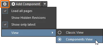
リビジョンの表示
 アイコンをクリックしてリビジョン選択のドロップダウンにアクセスすることで、パネルに表示するリビジョンを設定できます。
-
Load all pages – すべてのリビジョンを読み込むように選択します。
-
Show Hidden Revisions – 非表示のリビジョンを表示するように選択します。
-
Show only latest – 最新リビジョンのみを表示するように選択します。
-
View – アイテムをClassic Viewで表示するか、解釈ビュー(Components View/Project View)で表示するかを選択します。
フォルダ内容の読み込み
ExplorerパネルのServer Folders構造領域内で任意のフォルダをクリックすると、可能な場合はそのフォルダ内容の一部のみが最初に読み込まれます。これにより、フォルダの初回読み込み時間が大幅に短縮されます。初期表示分の末尾までスクロールすると、追加のフォルダ内容が読み込まれます。
フォルダの全内容を読み込むには、パネル上部の

ボタンをクリックし、関連メニューの
Load all pagesオプションを使用して、フォルダ内容の分割読み込み(オプション無効)から全件読み込み(オプション有効)へ切り替えます。
非表示リビジョンの表示
Related page: Workspaceのライフサイクル定義の作成 – Item Revisionの可視性と適用性の制御
Visible in Vault panels属性が無効になっているライフサイクル状態に入ったItem Revisionは、デフォルトではExplorerパネルに表示されません。さらにそれが当該Itemの最新リビジョンである場合、そのItemのエントリ全体が実質的に非表示になります。この可視性状態(状態レベルで定義)は、すべてのItemに対してグローバルに上書きできます。
現在表示されていないすべてのItem Revisionを表示するには、パネルのItems領域右上にあるコントロールをクリックし、関連メニューでShow Hidden Revisionsオプションを有効にします。

Explorerパネルでコンテンツを参照中に、非表示のItem Revisionを表示している例。画像にカーソルを合わせると結果が表示されます。
最新のItem Revisionのみを表示
時間の経過とともにWorkspace内のコンテンツは進化に伴って変更され、各変更は修正されたデータに対応するための新しいリビジョンを生みます。Itemを参照する際、通常必要なのは最新リビジョンのみです。それ以外の過去リビジョンはノイズとなり、設計者の視界を散らかしがちです。これを軽減するため、ExplorerパネルはデフォルトでItemの最新リビジョンのみを表示します。
ExplorerパネルでItemのすべてのリビジョンを表示するには、パネルのItems領域右上にあるコントロール をクリックし、関連メニューからShow only latestオプションを無効にします。
このオプションは、タイプ や配置されている表示フォルダに関係なく、Workspace内のすべてのItemに適用されるグローバル設定です。

デフォルトでは、ExplorerパネルはItemの最新リビジョンのみを表示します。画像にカーソルを合わせると、コマンドを無効にした例が表示されます。
散らかりを解消して最新リビジョンのみの表示に戻すには、オプションを再度クリックしてONに切り替えます。
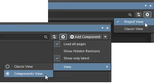
解釈ビュー
パネルには、ComponentsとProjectsに適用される2つの特別な解釈ビューも用意されています。パネル表示オプションがClassic Viewモードに変更されていない限り、ComponentまたはProjectを選択するとビューは自動的にこのスタイルへ切り替わります。
Classicまたは解釈ビュー(Component View / Project View)のオプションは、特別なアイテムタイプのいずれかが選択されているときに、ビューメニューから利用できます。
-
Classic View – ItemsとそのRevisionsのみを表示するように選択します。
-
Components View – リビジョンと解釈されたコンポーネントデータを表示するように選択します。詳細はComponent View を参照してください。
-
Project View – Project ReleaseデータおよびプロジェクトParametersへのアクセスを含む、プロジェクトの構造化されたグラフィック版を表示するように選択します。詳細はProject View を参照してください。
Item Revisionの比較
Altium Designerネイティブのファイル形式比較テクノロジーの力を活用し、Workspaceは、サポートされるさまざまなコンテンツタイプについて、同一または異なるItemの2つのリビジョンを、Explorerパネル内から直接ビジュアルに比較することをサポートします。次のコンテンツタイプのItemのリビジョンを比較できます。
-
Component Item
-
Symbol Item
-
Footprint Item
-
Managed Schematic Sheet Item
-
Schematic Template Item
-
PCB Fabrication Data Item
-
PCB Assembly Data Item
-
PCB Project Design Item
Explorerパネル内で該当フォルダへ移動し、比較したい2つのItem-Revisionを選択してから右クリックし、コンテキストメニューからOperations » Compareを選択します。
Comparing Two Component Item Revisions
2つのComponent Itemリビジョンを比較する場合、Compareをクリックした後、次の一連の処理が行われます。
-
参照されているFootprint Itemリビジョンが比較されます。
-
参照されているSymbol Itemリビジョンが比較されます。
-
2つのComponent Itemリビジョンのパラメトリックデータが比較されます。
比較結果はCompare component revisionsダイアログに表示されます。

コンポーネントの2つのリビジョンを比較した例。
ダイアログは3つの明確なセクションに分かれており、パラメトリックデータ、フットプリント、シンボルの比較結果を表示します。パラメータの値が一致しない場合は、赤みがかった背景でハイライト表示されます。フットプリントとシンボルについては、テキストで Identical または Not identical のいずれかが表示されます。
Show unchanged オプションを無効にすると、一致しない要素のみが残ります。
-
シンボルおよびフットプリントでは、対応する参照先の Item Revision に対して、関連する Compare コントロールをクリックすることで、Compare component revisions ダイアログから直接比較を実行できます。 フットプリントの場合、Compare をクリックすると Compare components ダイアログが開き、参照されている2つのフットプリントの比較を実行します。 シンボルの場合、Compare をクリックするとグラフィカル比較が実行され、検出された差分は Differences panel に一覧表示されます。 2つのリビジョンの回路図ライブラリドキュメントは、デザインエディタウィンドウで左右に並べて表示することで、ワークスペース内で開かれます。検出された差分のトップレベルフォルダをクリックすると、その差分が両方のドキュメント上で同時にハイライト表示されます。
-
Workspace で Part Choice Revision Control 機能が有効になっている場合、Compare component revisions ダイアログのパラメトリックデータ比較結果には、選択したコンポーネントリビジョンのパーツチョイスリストの比較結果も含まれます。比較は
<Manufacturer Name> + <Manufacturer Part Number> の組み合わせに基づいて実行され、Compare component revisions ダイアログ内の Part Choices の並び替えは、Key: <Rank>_<Manufacturer Name>_<Manufacturer Part Number> の降順です。
Comparing Two Symbol Item Revisions
Symbol Item の2つのリビジョンを比較する場合、Compare をクリックするとグラフィカル比較が行われ、検出された差分は Differences panel に一覧表示されます。2つのリビジョンの SchLib ドキュメントはデザインスペース内で開かれます。デザインエディタウィンドウで左右に並べて表示することで、差分をグラフィカルに確認できます。検出された差分のトップレベルフォルダをクリックすると、その差分が両方のドキュメント上で同時にハイライト表示されます。
これは、2つのソースドキュメントに対して Project » Show Physical Differences コマンドを実行した場合と同じ機能です。

シンボルの2つのリビジョンの比較例。
Comparing Two Managed Schematic Sheet Item Revisions
Managed Schematic Sheet Item の2つのリビジョンを比較する場合、Compare をクリックするとグラフィカル比較が行われ、検出された差分は Differences パネルに一覧表示されます。2つのリビジョンの SchDoc ドキュメントはデザインスペース内で開かれます。デザインエディタウィンドウで左右に並べて表示することで、差分をグラフィカルに確認できます。検出された差分のトップレベルフォルダをクリックすると、その差分が両方のドキュメント上で同時にハイライト表示されます。
これは、2つのソースドキュメントに対して Project » Show Physical Differences コマンドを実行した場合と同じ機能です。

Managed Schematic Sheet Item の2つのリビジョンの比較例。
Comparing Two Schematic Template Item Revisions
Schematic Template Item の2つのリビジョンを比較する場合、Compare をクリックするとグラフィカル比較が行われ、検出された差分は Differences パネルに一覧表示されます。2つのリビジョンの SchDot ドキュメントはデザインスペース内で開かれます。デザインエディタウィンドウで左右に並べて表示することで、差分をグラフィカルに確認できます。検出された差分のトップレベルフォルダをクリックすると、その差分が両方のドキュメント上で同時にハイライト表示されます。
これは、2つのソースドキュメントに対して Project » Show Physical Differences コマンドを実行した場合と同じ機能です。

異なる2つの Schematic Template Item のリビジョン比較例。
Comparing Released Board Content
PCB Fabrication Data Item、PCB Assembly Data Item、または PCB Project Design Item の2つのリビジョンを比較する場合、比較結果は Compare Project Revisions ダイアログに表示されます。これは生成されたファイル構造の比較と、その構造内のファイルのチェックを行うだけのものです。色分けされたオプションにより、変更された/変更されていないファイル、および追加/削除されたファイルが示されます。これらのエントリの表示は、有効/無効の切り替えでトグルできます。
必要なプロジェクトのフォルダを Classic View で表示していることを確認してください(
Explorer パネル右上の
ボタンをクリックし、コンテキストメニューから
Classic View コマンドを選択します)。

PCB Assembly Data Item の2つのリビジョンの比較例。
グリッドデータのエクスポート
Explorer パネルは、グリッドビューのデータを csv または xls 形式のファイルへエクスポートする機能をサポートしています。この機能が利用できる例は次のとおりです。
-
Component Items グリッド(Classic ビューおよび Component ビューの両方)。
-
Items グリッド。
-
Preview アスペクトビュータブ上の Linked models グリッド(選択した Component Item に対して)。
-
検索結果グリッド。
-
Where-used アスペクトビュータブ上の Item グリッド。
-
Children アスペクトビュータブ上の Item グリッド。
グリッド内で右クリックし、コンテキストメニューから Operations » Export Grid コマンドを選択します。Select columns for data export ダイアログが表示されます。列リストのチェックボックス、または Select All / Deselect All ボタンを使用して、エクスポートしたいデータを有効/無効にします。 このダイアログには、そのグリッドで使用可能なすべての列が含まれており、パネルで現在表示されている列は既定でエクスポートが有効になっています。OK をクリックすると、標準の Windows Save As ダイアログが表示されます。このダイアログで、エクスポートファイルの保存先とファイル名を指定します。Save as type フィールドでファイル形式を選択します。Comma-Separated Values Files(*.csv)または Excel Files(*.xls)のいずれかです。
エクスポートの進行状況は Export Data ダイアログに表示されます。正常にエクスポートされたら、Explore ボタンを使用してエクスポートフォルダをすばやく参照できます。あるいは、Open ボタンを使用してエクスポートしたファイルを直接開くこともできます。
。")
データのエクスポート例(選択した Component Item リビジョンの linked models を Excel 形式ファイルへ)。
Project View
パネルの解釈された Project View は、選択したプロジェクトをプロセス指向のビューで表示し、関連するプロジェクトデータおよびそのリリースへ直接アクセスできるようにします。
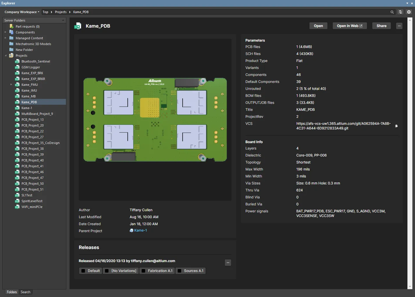
Project View には、プロジェクトのプレビュー、主要な説明、パラメータ、リリースが表示されます。
Releases 領域には、選択したプロジェクトに関連付けられた Project Release(s) の一覧が表示され、各リリースの概要と、それを構成するパッケージが含まれます。この領域の ボタンをクリックすると Batch state change dialog が開き、同一リリースに関連する複数アイテムのライフサイクル状態を、単一のバッチ処理で一括変更できます。
プロジェクトビュー右上のコントロールには次が含まれます。
-
Open – 対象プロジェクトを Altium Designer で開くために使用します。
-
Open in Web – Workspace のブラウザベースのインターフェースでプロジェクトを開くために使用します。
-
Share – Share dialog を開くために使用します。これにより、ソフトウェア内から直接、世界中の他者と設計プロジェクトを共有できます。
-
– ボタンをクリックして、次のコマンドにアクセスします。
-
Make a copy – Create Project Copy ダイアログを開くために使用します。これはプロジェクトをコピーし、接続された Workspace に保存するためのものです。既定では、元のプロジェクト名にサフィックス
' - Copy' を付けた名前が使用されます。
-
History – プロジェクトの History view を開くために使用します。これは、そのプロジェクトの詳細な CAD 中心の管理ページから利用できます。
-
Delete – プロジェクト、そのフォルダ、およびすべてのプロジェクトコンテンツを削除するために使用します。削除が完了する前に確認が求められます。


 AI で翻訳