在大型设计中,一个常见的挑战是保持网络(Nets)的可管理性。这不仅仅是从设计师创建连接性的角度出发,也是从需要解读和理解原理图的读者的角度来看。这在跨页连接时尤其重要,因为这是设计师和读者最容易混淆的时刻。
如果设计包含高引脚计数的组件,使用单独的导线创建所有的连接是不切实际的。如果它们是数值递增的一组,比如Data0, Data1等,可以将多个网络捆绑到一个总线(Bus)中。或者,任何网络和总线的组合都可以捆绑到一个信号束(Signal Harness)中,这提供了一种在设计中传输多个网络的视觉上和逻辑上整洁的方式。
使用总线
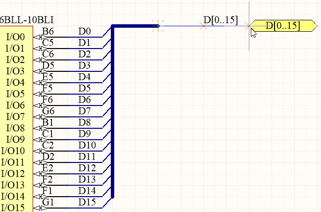
总线用于捆绑一系列顺序的网络,例如地址总线或数据总线。它们的核心要求是每个网络都以一个共同的基本名称命名,后面跟着一个数字标识符,如下图所示。例如,网络Control1、Control2和Control3可以被捆绑到总线Control[1..3]中。总线不能用于捆绑一组不相关的网络,例如网络Enable、Read和Status,信号束用于此目的,如下所述。
要创建一个有效的总线,它必须包含以下所有元素(如下图所示):
- 每个单独网络上的网络标签
- 总线上的网络标签
- 如果总线离开此页面,则端口名称与总线相同


上图所示的所有元素都必须包含在内,才能创建有效的总线。只有当您想要从总线的两侧撕下不同的总线元素时,才需要使用总线条目。
总线不会被传输到PCB上,而是可以为每个原理图总线创建一个网络类,或者如果需要,为每个总线段创建一个网络类。通过指定实际上是更大总线的一部分的总线来创建总线段,例如,来自总线`D[15..0]`。如果启用了这个选项,那么PCB将包括整个总线的网络类,以及已经定义的每个段。在“项目选项”对话框的
类生成标签中启用所需选项。
总线是一个多段线对象,用于定义多个网络的连接。
## 概述
总线是一个表示多线连接的多段线对象,是电气设计的基本元素。
## 可用性
总线仅在原理图编辑器中通过以下方式可用:
- 从原理图编辑器主菜单中选择 **放置» 总线**。
- 点击位于设计空间顶部 **活动栏** 上的网络布线对象下拉菜单中的总线按钮(

)。长按 **活动栏** 按钮以访问其他相关命令。一旦使用了某个命令,它将成为该部分 **活动栏** 上的最顶端项目。
- 点击 **布线** 工具栏上的
按钮(激活方式为 **查看» 工具栏» 布线**)。
- 右键点击并选择 **放置» 总线** 从上下文菜单中。
## 放置
启动命令后,光标将变为十字形,表示进入总线放置模式。放置操作通过执行以下一系列动作完成:
1. 点击或按 **Enter** 键确定总线的起始点。
2. 定位光标,然后点击或按 **Enter** 键确定一系列顶点,这些顶点定义了总线的形状。
3. 放置最后一个顶点后,右键点击或按 **Esc** 键完成总线的放置。
4. 继续放置更多总线对象,或右键点击或按 **Esc** 键退出放置模式。
5. 使用 **Backspace** 或 **Delete** 键移除最后放置的总线段。
### 放置模式
放置总线时,有三种“手动”放置模式,其中两种具有拐角方向选项。这些模式指定了放置总线时创建拐角的方式以及总线可放置的角度。
放置过程中:
- 按 **Tab** 键暂停放置并从中访问 **总线** 模式的 **属性** 面板,可即时更改其线条属性。点击设计空间暂停按钮覆盖层(

)以恢复放置。
- 按 **Shift+Spacebar** 在三种手动模式:**90°**、**45°** 和 **任意角度** 之间切换。
- 在 **90°** 或 **45°** 模式(称为真正的正交模式)中,按 **Spacebar** 在拐角方向选项之间切换。在这些模式中,附着在光标上的线段是一个 **前瞻** 段 - 实际放置的段位于此前瞻段之前。
- 放置过程中,当前放置模式将在设计空间的状态栏(位于设计空间最底部)中显示。您可以在总线放置过程中随时更改模式。
 45度模式
 90度模式
 任意角度模式。按 **Shift+Spacebar** 在不同放置模式之间切换。
在放置过程中修改的属性(通过使用 **Tab** 访问 **属性** 面板)将成为后续放置的默认设置,除非在 **原理图 - 默认** 对话框的 **首选项** 页面上启用了 **永久** 选项。启用此选项时,所做的更改仅影响正在放置的对象以及在同一放置会话期间放置的后续对象。
### 自动路径模式
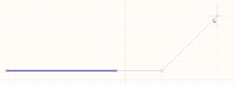
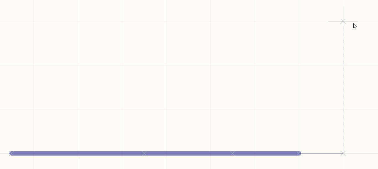
第四种可用的总线放置模式是 **自动布线** 模式,可用于使用 **点对点路由器** 从前一个段的末端快速路由到点击的光标点。在 **Shift+Spacebar** 选择周期中启用时,模式由从段顶点到光标的粗点线表示。
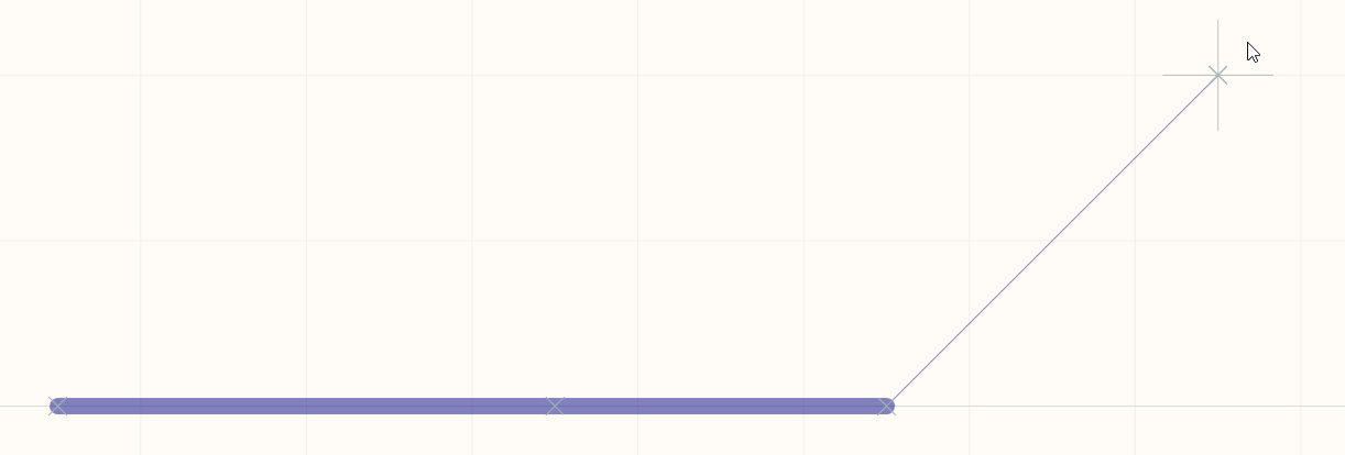
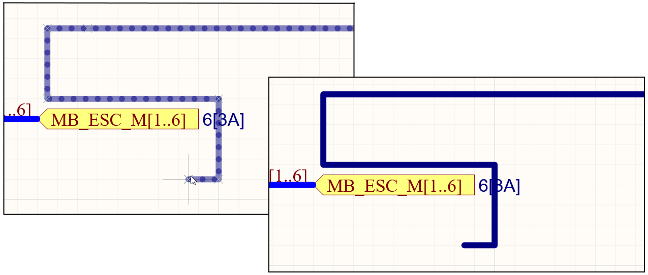 在 **自动布线** 模式下放置总线段,如由点线路径线所示。放置(右侧)时,总线路径将自动避开障碍物。
路由的路径将尽可能高效地避开工作表上已放置的现有对象。在此模式下按 **Tab** 配置适用选项的 **点对点路由器选项** 对话框。
### 电气吸附
除了网格吸附功能外,原理图编辑器还支持对可用电气连接的吸附。当正在放置的对象,如总线,落在有效电气连接的可定义吸附距离内时,光标将跳转到该电气“热点”(显示为红色十字)。
 电气吸附点由红色十字表示。
电气对象热点吸附可在原理图 **文档选项** 模式下的 **属性面板** 的 **常规** 部分中配置。
## 图形编辑
图形编辑方法允许直接在设计空间中选择已放置的总线对象,并图形化地更改其大小和/或形状。
当选择总线对象时,将提供以下编辑手柄:
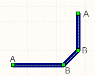 选中的总线,准备进行图形编辑。
- 点击并拖动非手柄点以重新定位整个总线。当总线未被选中时,点击、按住并拖动以重新定位它。
- 点击并拖动 **A** 以重新定位总线的端点。
- 点击并拖动 **B** 以移动总线顶点。其他顶点将保持锚定。
- 点击并按住顶点,然后在键盘上按 **Delete** 以移除该顶点。
选中总线后,点击一个段以单独选择该段。这种总线“子选择”通过相关编辑手柄变为红色来区分。
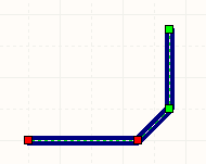 单独段子选择。
然后可以直接使用 **SCH 列表** 面板编辑该段的相关顶点,任何更改都会立即显示在原理图上。
如果尝试图形化修改具有 **锁定** 属性启用的对象,将出现一个对话框,询问是否确认进行编辑。如果在 **原理图 - 图形编辑** 对话框的 **首选项** 页面上启用了 **保护锁定对象** 选项,并且该设计对象的 **锁定** 选项也被启用,则无法选择或图形化
总线属性
原理图编辑器对象属性是可定义的选项,用于指定放置对象的视觉样式、内容和行为。每种类型对象的属性设置以两种不同方式定义:
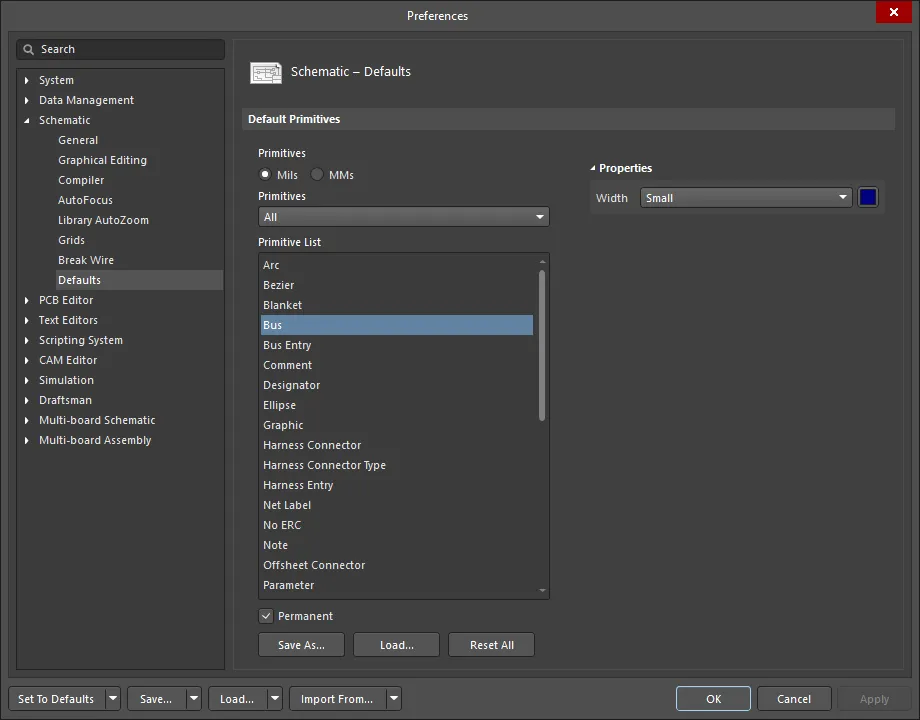
- 放置前设置 - 大多数总线对象属性,或那些逻辑上可以预先定义的属性,可作为可编辑的默认设置在原理图 - 默认值页面上的首选项对话框中访问(通过设计空间右上角的
 按钮访问)。选择原始图元列表中的对象以在右侧显示其选项。
- 放置后设置 - 所有总线对象属性在选择设计空间中放置的总线后,可在总线对话框和属性面板中编辑。

如果在
首选项对话框的
原理图 - 图形编辑页面上禁用了
双击运行交互式属性选项(默认),当双击原始图元或右击选择的原始图元然后选择
属性时,将打开对话框。当启用
双击运行交互式属性选项时,将打开
属性面板。
虽然对话框和面板中的选项相同,但选项的顺序和位置可能略有不同。
在下面的属性列表中,不作为首选项对话框中的默认设置提供的选项标注为“属性面板仅限”。
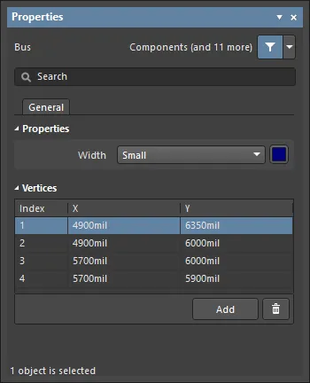
属性
顶点(属性面板仅限)
此区域用于修改当前选定区域对象的各个顶点。您可以修改现有顶点的位置,根据需要添加新顶点或删除顶点。总线连接可以在顶点之间定义,并且还支持将顶点信息导出到并从CSV格式的文件中导入。
- 顶点网格 - 列出了对象当前定义的所有顶点点,包括:
- 索引 - 顶点的分配索引(不可编辑)。
- X - 顶点的X(水平)坐标。点击编辑。
- Y - 顶点的Y(垂直)坐标。点击编辑。
- 添加 - 点击以添加一个新的顶点点。新顶点将添加在当前聚焦的顶点条目下方,并最初具有与聚焦条目相同的X,Y坐标。点击
 删除当前选定的顶点。
[折叠 collapsed class="" title="总线入口" id="bus_entry"]
 总线入口可用于将导线连接到总线上。
概述
总线入口是一种电气设计基元,用于将导线连接到总线线上。它能够允许两个不同的网络连接到总线上的同一点——如果使用导线进行此操作,两个网络将会短路。如果不需要这种能力,就不必使用总线入口。
可用性
总线入口仅在原理图编辑器中通过以下方式可用:
- 从主菜单选择放置» 总线入口。
- 点击位于设计空间顶部的活动栏上的网络布线对象下拉菜单中的总线入口按钮 (
 )。点击并按住活动栏按钮以访问其他相关命令。一旦使用了某个命令,它将成为该部分活动栏上的最顶端项目。
- 点击布线工具栏上的按钮(点击查看» 工具栏» 布线以激活)。
- 右键点击然后选择上下文菜单中的放置» 总线入口。
放置
启动命令后,光标将变为十字形,您将进入总线入口放置模式。
- 点击或按Enter在光标位置放置一个总线入口。
- 按空格键逆时针旋转总线入口(以90°的增量)或按Shift+空格键顺时针旋转。
- 在放置模式下按X或Y键沿X轴或Y轴镜像总线入口。
- 继续放置总线入口或右键点击或按Esc退出放置模式。
在放置过程中,按Tab键暂停过程并访问属性面板中的总线入口模式,从而可以即时更改其线属性。点击设计空间暂停按钮覆盖层 () 以恢复放置。
放置过程中通过属性面板修改的属性将成为进一步放置的默认设置,除非在首选项对话框的原理图 - 默认页面上启用了永久选项。启用此选项时,所做的更改仅影响正在放置的对象以及在同一放置会话期间放置的后续对象。
图形编辑
要移动总线入口,点击并按住它(光标将跳转到最近的电气热点),然后将其移动到新位置 - 连接的总线和导线将保持连接。在移动总线入口时,使用X和Y键改变其在这些轴上的方向。
如果尝试图形修改一个其锁定属性已启用的对象,将出现一个对话框,询问是否继续进行编辑。如果在首选项对话框的原理图 - 图形编辑页面上启用了保护锁定对象选项,并且该设计对象的锁定选项也已启用,则该对象无法被选择或图形编辑。点击锁定对象以选择它,然后在列表面板中禁用锁定属性或禁用保护锁定对象选项以图形编辑对象。
非图形编辑
以下是可用的非图形编辑方法。
通过总线入口对话框或属性面板编辑
面板页面: 总线入口属性
此编辑方法使用关联的总线入口对话框和属性面板模式来修改总线入口对象的属性。

 左侧为总线入口对话框,右侧为属性面板中的总线入口模式
放置后,可以通过以下方式访问总线入口对话框:
- 双击放置的总线入口对象。
- 将光标悬停在总线入口对象上,右键点击然后从上下文菜单中选择属性。
在放置过程中,可以通过按Tab键访问属性面板中的总线入口模式。一旦放置了总线入口,所有选项都会出现。
放置后,可以通过以下方式之一访问属性面板中的总线入口模式:
- 如果属性面板已经处于活动状态,通过选择总线入口对象。
- 在选择总线入口对象后,从设计空间右下部分的面板按钮中选择属性面板,或通过主菜单选择查看» 面板» 属性。
在进入放置模式之前,可以从
首选项对话框的
原理图 - 默认页面访问总线入口属性。这允许更改总线入口对象的默认线属性,这些属性将应用于放置后续总线入口时。
编辑多个对象
属性面板支持多个对象编辑,
总线入口属性
原理图编辑器对象属性是定义选项,用于指定放置对象的视觉样式、内容和行为。每种类型对象的属性设置以两种不同方式定义:
- 放置前设置 - 大多数总线入口对象属性,或那些可以逻辑上预先定义的属性,可作为可编辑的默认设置在原理图 - 默认值页面上的首选项对话框中找到(通过设计空间右上角的按钮访问)。选择原始图元列表中的对象以在右侧显示其选项。

- 放置后设置 - 所有总线入口对象属性在放置的总线入口被选中时,可在总线入口对话框和属性面板中编辑。

如果在
首选项对话框的
原理图 - 图形编辑页面上禁用了
双击运行交互式属性选项(默认),当双击原始图元或右击选中的原始图元然后选择
属性时,将打开对话框。当启用
双击运行交互式属性选项时,将打开
属性面板。
虽然对话框和面板中的选项相同,但选项的顺序和位置可能略有不同。
属性
- 起点 (X/Y)
- X (第一个字段) - 相对于当前设计空间原点的对象参考点的当前X(水平)坐标。编辑以更改对象的X位置。值可以以公制或英制输入;输入非当前默认单位的值时,需包含单位。
- Y (第二个字段) - 相对于当前原点的对象参考点的当前Y(垂直)坐标。编辑以更改对象的Y位置。值可以以公制或英制输入;输入非当前默认单位的值时,需包含单位。
- 终点 (X/Y) -
- X (第一个字段) - 相对于当前设计空间原点的对象参考点的当前X(水平)坐标。编辑以更改对象的X位置。值可以以公制或英制输入;输入非当前默认单位的值时,需包含单位。
- Y (第二个字段) - 相对于当前原点的对象参考点的当前Y(垂直)坐标。编辑以更改对象的Y位置。值可以以公制或英制输入;输入非当前默认单位的值时,需包含单位。
- 尺寸 (X/Y) - 总线入口的尺寸。
- 宽度 - 使用下拉菜单选择所需的宽度。
- 颜色 - 点击颜色框选择对象的所需颜色。
使用信号束
信号束具有很高的灵活性,因为它们可以用来捆绑任意数量的网络、总线和低级别的束。正如它们的名字所暗示的,它们类似于一个布线束,任何排列的电线都可以被捆绑并通过电子或电气产品进行布线。创建和管理它们更加复杂,但是它们的好处是可以极大地简化原理图的展示并增强其可读性。

信号束用于捆绑任意组合的网络、总线和低级信号束。
构成完整信号束的元素包括:
