
Text
 A placed Text object
Text is a non-electrical drawing primitive. It is a single line of free text that can be placed on a PCB document. Uses might include section headings, revision history, timing information, or some other descriptive or instructive text. The text that will be displayed is entered through the Inspector panel.
Text Object
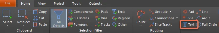
Text is available for placement in both the PCB editor by choosing Home | Place | Text.
After launching the command, the cursor will change to a cross-hair and you will enter text object placement mode. Placement is made by moving the cursor to the desired location, then left-clicking or pressing Enter to complete placement.
Additional actions that can be performed during placement while the text is still floating on the cursor and before its left-hand edge is anchored are:
- Press the Tab key to pause the placement and access the Text mode of the Inspector panel in which its properties can be changed on the fly. Click the design space pause button overlay (
 ) to resume placement.
 - Press the Spacebar to rotate the text counterclockwise or Shift+Spacebar for clockwise rotation. Rotation is in increments of 90°.
- Press X to mirror the text along the X-axis.
Graphical Editing
This method of editing allows you to select a placed text object in the design space and graphically change its length, height, or location.
When a text object is selected, click and drag the editing handles to resize the text.

A selected Text object
Click anywhere on the text, away from editing handles, then drag to reposition it. While dragging, the text can be rotated (Spacebar/Shift+Spacebar) or mirrored (X to mirror along the X-axis).
Non-Graphical Editing
This method of editing uses the Inspector panel mode to modify the properties of a text object.

During placement, the Text mode of the Inspector panel can be accessed by pressing the Tab key. Once the text is placed, all options appear.
After placement, the Text mode of the Inspector panel can be accessed in one of the following ways:
- Double-clicking on the placed hyperlink object.
- If the Inspector panel is already active, select the text object, right-click then choose Properties from the context menu.
- With the text selected, click View | PCB | Inspector from the main ribbons.
Text Actions
Right-click over a placed text object to open a context-sensitive menu in which you can lock the placed text object.
Text Properties
All Text object properties are available for editing in the Inspector panel when a placed Text is selected in the design space.
- Text - enter the text you'd like reflected in the design space.
- Layer - use the drop-down to select the desired layer. Enable Mirror if desired.
- Text Height - use this field to enter the desired text height.
- Font Type
- TrueType - select to use fonts available on your PC (in the \Windows\Fonts folder). TrueType fonts offer full Unicode support. By default, the software links to a used TrueType font (they are not stored in the PCB file), which means the same font must be present on each computer to which the design is moved.
- Justification - use to set the location of the designator within the border rectangle.
- Font - use the drop-down to select the desired TrueType font. Use the B (bold) and/or I (italic) options to add emphasis to the text as required.
- Inverted - use to have the text displayed as inverted with control over the size of the border around the text. You can use the following options to further configure the text:
- Size (Width/Height) -
- Width - the width of the border rectangle.
- Height - the height of the border rectangle.
- Size (Width/Height) -
- Inverted - use to have the text displayed as inverted with control over the size of the border around the text. You can use the following options to further configure the text:
- Stroke
- Justification - use to set the location of the designator within the border rectangle.
- Font - use the drop-down to select the desired Stroke font. Choices are:
- Stroke Width - displays the width of the stroke.
- TrueType - select to use fonts available on your PC (in the \Windows\Fonts folder). TrueType fonts offer full Unicode support. By default, the software links to a used TrueType font (they are not stored in the PCB file), which means the same font must be present on each computer to which the design is moved.
- Border Mode
- Margin - click this button to enable the editing of the Margin Border option.
- Text Offset - the amount the designator is offset back from the edge/corner that it is justified against. This option has no effect when the Center justification mode is chosen. This option is not available for Margin.
- Offset - click this button to enable the editing of the Text Offset option.
- Margin Border - use to specify the size of the margin border surrounding the designator. This option is not available for Offset.
- Margin - click this button to enable the editing of the Margin Border option.