
Solid Region

Examples of the various types of placed region objects
A solid region, also known as a region, is a polygonal-shaped primitive object that can be placed on any layer. A region can have any number of sides and vertices (corners). It can be placed on a signal layer to define an area of solid copper to be used to provide shielding or to carry large currents. Positive regions can be combined with tracks or arc segments and be connected to a net. In the PCB Library editor, regions can be used to create custom pad shapes on copper layers or special mask shapes on the solder and paste masks. On non-electrical layers, regions can be used to define custom shapes for tasks such as logos.
A solid region can be configured to be positive, for example, placed as a copper region or negative, for example, placed as a polygon pour cutout. By placing it as a negative on the multi-layer, it can be placed as a board cutout. When placed as a negative, a region can create a cutout (void) in a polygon pour. In this mode, the region will not be filled with copper when the polygon is poured. When used as a negative region for a board cutout (by placing it on the multi-layer), it defines an area that becomes a hole through the finished board. Board cutout regions are transferred to Gerber and ODB++ files for manufacturing purposes through the use of a dedicated Rout layer.
Solid Region Object
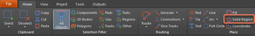
Regions are available for placement in the PCB editor by choosing Home | Place | Solid Region from the main menus.
After launching the command, the cursor will change to a crosshair and you will enter region placement mode. Placement is made by performing the following sequence of actions:
- Position the cursor then click to anchor the starting vertex for the region.
- Move the cursor to define the location of the second vertex. The default behavior is to place two edges with each click, with a user-defined corner shape between them. Refer to the Graphical Editing section below for more details on changing corner modes.
- Continue to move the mouse and click to place further vertices.
- After placing the final vertex, right-click or press Esc to close and complete placement of the region. There is no need to manually close the region as the software will automatically complete the shape by connecting the start point to the final point placed.
- Continue placing further regions or right-click or press Esc to exit placement mode.
Additional actions that can be performed during placement include:
- Press the Tab key to pause the placement and access the Region mode of the Inspector panel from where its properties can be changed on the fly. Click the design space pause button overlay (
 ) to resume placement.
 - Press the + and - keys on the numeric keypad to cycle forward and backward through all layers currently visible in the design.
- Press the * key to cycle through the visible signal layers.
Graphical Editing
Move Region Vertices
Regions contain two points, or handles, with which you can edit the shape of the region.
- Full Handles - located at the corners of the region.
- Empty Handles - located in the centers of the segments created by the Full Handles.
An existing region can be re-shaped by moving these handles, or vertices, located at each corner or at the center of each edge.
To modify the region shape:
- Click and select a region, which will highlight the vertices for the region and change the cursor to a crosshair.
- Click on a Full Handle to move that corner.
- Click along an edge to move the entire edge.
- Click on an Empty Handle to move the whole side (for track and for arc).
- Ctrl+Click on an Empty Handle to break that edge into two edges. Ctrl only needs to be held at the beginning of the movement. Shift+Spacebar can then be used to cycle through modes (Mitering to arc, Moving vertex, and Mitering to segment), which display at the bottom of the main editor space.

- If the Any angle placement mode creates unwanted vertices, or to remove extra vertices in general, click Ctrl and grab the central full handle. An X icon appears over the handle and dragging the edge will reduce the vertices on that edge to one.

Modify Region Border
In addition to vertex editing, you also can use the Modify Region Border command to easily change the shape of polygons. The command is run by right-clicking on the desired polygon then selecting Polygon Actions » Modify Polygon Border. Once the command is launched, the cursor becomes a crosshair. Each time you click, a new vertex is added. As during region placement, the Shift+Spacebar shortcuts can be used to change corner shapes.

Non-Graphical Editing
This method of editing uses the Inspector panel mode to modify the properties of a Region object.

During placement, the Region mode of the Inspector panel can be accessed by pressing the Tab key. Once the Region is placed, all options appear.
After placement, the Inspector panel can be accessed by:
- Double-clicking on the placed Region object.
- Placing the cursor over the Region object, right-clicking then choosing Properties from the context menu.
After placement and if the Inspector panel is already open, the Region mode of the Inspector panel can be accessed by selecting the Region object.
Solid Region Properties
All Solid Region properties are available for editing in the Inspector panel when a placed Solid Region is selected in the design space.
Properties
- Net - use to choose a net for the region. All nets for the active board design will be listed in the drop-down list. This field is not available for a PCBLIB document.
- Layer - this field is available only when Kind is set to Copper, Polygon Cutout, or Cavity. Use it to specify the layer on which the region is placed. For Copper and Polygon Cutout, all defined (and enabled) layers for the active board design are listed in the drop-down list. For Cavity, only enabled mechanical layers are listed.
- Kind - use the drop-down to select the function of the region:
- Copper - a solid, positive area that can be placed on any design layer, such as a signal (copper) layer.
- Polygon Cutout - functions as a polygon cutout defining a negative or no-copper area within a polygon. Repour the polygon after placing a Cutout.
- Board Cutout - functions as a board cutout defining a negative area or hole within the board shape.
- Cavity - used to define an embedded cavity within which a component will reside 'inside the board'. A region of this kind only can be placed on a suitable mechanical layer and must completely enclose the 3D body of the component with sufficient clearance on each side. Check with the fabricator to find out how much clearance is required.
- Arc Approximation - enter the maximum deviation from a perfect arc.
- Area - displays the area of the region object.
- (X/Y) - displays the X and Y axis of the region object.
- Locked icon - toggle to protect/unprotect the region from being graphically edited.
Outline Vertices
This region is used to modify the individual vertices of the currently selected region object. You can modify the locations of existing vertices, add new vertices or remove them as required. Arc connections between vertex points can be defined and support is also provided for exporting vertex information to and importing from a CSV-formatted file. You also can adjust the position of the region object by globally applying delta-x/delta-y values to all vertex points.
- Vertices Grid - lists all of the vertex points currently defined for the region in terms of:
- Index - the assigned index of the vertex (non-editable).
- X - the X (horizontal) coordinate for the vertex. Click to edit.
- Y - the Y (vertical) coordinate for the vertex. Click to edit.
- Arc Angle (Neg = CW) - the angle of an arc that is drawn to connect this vertex point to the next. By default, connections are straight-line edges with this field remaining blank. Click to edit then enter an arc angle as required. Entry of a positive value will result in an arc drawn counterclockwise. To draw a clockwise arc, enter a negative value.
- Add - click to add a new vertex point. The new vertex will be added below the currently focused vertex entry and will initially have the same X and Y coordinates as the focused entry. Click
 to remove the currently selected vertex.
Paste Mask Expansion
- Rule/Manual - select the desired paste mask expansion configuration. When Manual is selected, you can enable and enter the desired measurement.
Solder Mask Expansion
- Rule/Manual - select the desired solder mask expansion configuration. When Manual is selected, you can enable and enter the desired measurement.