
Coordinate

A placed Coordinate
A coordinate is a group design object. It is used to mark the X (horizontal) and Y (vertical) distance of a point in the design space relative to the current origin. Coordinates can be placed on any layer.
Coordinate Object
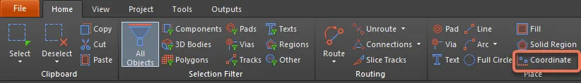
Coordinates are available for placement in the PCB editor by choosing Home | Place | Coordinate.
After launching the command, the cursor will change to a cross-hair and you will enter coordinate placement mode. A coordinate will appear "floating" on the cursor:
- Position the cursor and click or press Enter to place a coordinate.
- Continue placing further coordinates, or right-click or press Esc to exit placement mode.
Additional actions that can be performed during placement are:
- Press the L key to flip the coordinate to the other side of the board.
- Press the + and - keys (on the numeric keypad) to cycle forward and backward through all visible layers in the design respectively – to change the placement layer quickly.
Graphical Editing
This method of editing allows you to select a placed coordinate object directly in the design space and change its location graphically. The size and shape of a coordinate object cannot be changed graphically.
As such, editing handles are not available when the coordinate object is selected:

A selected Fill
Click anywhere on the coordinate and drag to reposition it. The position values are automatically updated as the coordinate is moved.
Non-Graphical Editing
This method of editing uses the Inspector panel to modify the properties of a Coordinate object.
During placement, the Coordinate mode of the Inspector panel can be accessed by pressing the Tab key. Once the Coordinate is placed, all options appear.
After placement, the Coordinate mode of the Inspector panel can be accessed in one of the following ways:
- If the Inspector panel is already open, select the Coordinate object.
- With the Coordinate selected, choose View | PCB | Inspector from the main ribbons.
Editing Multiple Objects
The Inspector panel supports multiple object editing, where the property settings that are identical in all currently selected objects may be modified. When multiples of the same object type are selected manually, an Inspector panel field entry that is not shown as an asterisk (*) may be edited for all selected objects.
Coordinate Properties
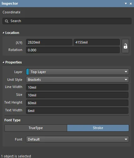
All Coordinate object properties are available for editing in the Inspector panel when a placed Coordinate is selected in the design space.
Location
- (X/Y)
- X (first field) - the current X (horizontal) coordinate of the reference point of the fill, relative to the current design space origin. Edit to change the X position of the fill. The value can be entered in either metric or imperial; include the units when entering a value whose units are not the current default.
- Y (second field) - The current Y (vertical) coordinate of the reference point of the fill, relative to the current origin. Edit to change the Y position of the fill. The value can be entered in either metric or imperial; include the units when entering a value whose units are not the current default.
- Rotation - the coordinates' angle of rotation (in degrees), measured counter-clockwise from zero.
Properties
- Layer - use the drop-down to determine the layer in which you'd like the object placed.
- Unit Style - use the drop-down to determine the unit style you'd like to use for the object.
- Line Width - enter the desired line width.
- Size - enter the desired size of the object.
- Text Height - enter the desired text height.
- Text Width - enter the desired text width.
Font Type
- TrueType - select to use fonts available on your PC (in the \Windows\Fonts folder). TrueType fonts offer full Unicode support. By default, the software links to a used TrueType font (they are not stored in the PCB file), which means the same font must be present on each PC to which the design is moved.
- Font - use the drop-down to select the desired TrueType font. Use the B (bold) and/or I (italic) options to add emphasis to the text as required.
- Stroke
- Font - use the drop-down to select the desired Stroke font. Choices are:
Default -a simple vector font designed for pen plotting and vector photo plotting.Sans Serif- acomplex font that will slow down vector output generation, such as Gerber.Serif- acomplex font that will slow down vector output generation, such as Gerber.
- Font - use the drop-down to select the desired Stroke font. Choices are: