
Graphic

A graphic is a non-electrical drawing primitive. It is essentially a container for an image file that can be imported and placed onto a PCB.
The graphic image is converted into black and white, then into primitives and is inserted as primitives or regions.
Graphic Object
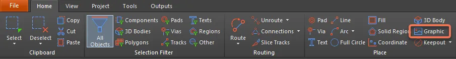
Graphics/images are available for placement in the PCB editor by choosing Home | Place | Graphic from the main menus.
After launching the command, the cursor will change to a crosshair and you will enter graphic placement mode.
- Position the cursor then click or press Enter to anchor the first corner of the graphic's frame in which the graphic itself will reside.
- Move the cursor to adjust the size of the frame then click or press Enter to complete frame placement.
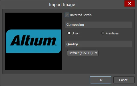
- A dialog will open in which you can browse to and select the required graphic. Select the file you want to insert then press Open to complete graphic placement.
- The Import Image dialog opens in which you can configure the graphic's settings.
Graphical Editing
This method of editing allows you to select a placed graphic object in the design space and graphically change its length, height, or location.
When a graphic object is selected, click and drag the editing handles to resize.

Click anywhere on the graphic away from editing handles then drag to reposition it. While dragging, the graphic can be rotated (Spacebar/Shift+Spacebar) or mirrored (X to mirror along the X-axis).
Non-Graphical Editing
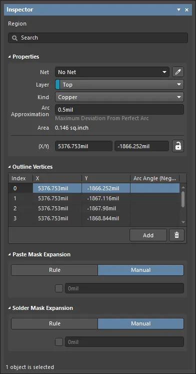
Since the graphic image is converted into primitives and is inserted as primitives or regions, this method of editing uses the Region mode of the Inspector panel to modify the properties of a graphic.
After placement, the Inspector panel can be accessed in one of the following ways:
- Double-clicking on the placed object.
- If the Inspector panel is already active, select the object, right-click then choose Properties from the context menu.
- With the object selected, click View | PCB | Inspector from the main ribbons.
Editing Multiple Objects
The Inspector panel supports multiple object editing, where the property settings that are identical in all currently selected objects may be modified. When multiples of the same object type are selected manually, an Inspector panel field entry that is not shown as an asterisk (*) may be edited for all selected objects.
Graphic Properties
PCB Editor object properties are definable options that specify the visual style, content and behavior of the placed object.
All Graphic object properties are available for editing in the Inspector panel in Region mode when a placed graphic is selected in the design space.
Properties
- Net - use to choose a net for the region. All nets for the active board design will be listed in the drop-down list. This field is not available for a PCBLIB document.
- Layer - this field is available only when Kind is set to Copper or Polygon Cutout. Use it to specify the layer on which the region is placed. For Copper and Polygon Cutout, all defined (and enabled) layers for the active board design are listed in the drop-down list.
- Kind - use the drop-down to select the function of the region:
- Copper - a solid, positive area that can be placed on any design layer, such as a signal (copper) layer.
- Polygon Cutout - functions as a polygon cutout defining a negative or no-copper area within a polygon. Repour the polygon after placing a Cutout.
- Board Cutout - functions as a board cutout defining a negative area or hole within the board shape.
- Arc Approximation - enter the maximum deviation from a perfect arc.
- Area - displays the area of the region object.
- (X/Y) - displays the X and Y-axis of the region object.
- Locked icon - toggle to protect/unprotect the region from being graphically edited.
Outline Vertices
This region is used to modify the individual vertices of the currently selected region object. You can modify the locations of existing vertices, add new vertices or remove them as required. Arc connections between vertex points can be defined and support is also provided for exporting vertex information to and importing from a CSV-formatted file. You also can adjust the position of the region object by globally applying delta-x/delta-y values to all vertex points.
- Vertices Grid - lists all of the vertex points currently defined for the region in terms of:
- Index - the assigned index of the vertex (non-editable).
- X - the X (horizontal) coordinate for the vertex. Click to edit.
- Y - the Y (vertical) coordinate for the vertex. Click to edit.
- Arc Angle (Neg = CW) - the angle of an arc that is drawn to connect this vertex point to the next. By default, connections are straight-line edges with this field remaining blank. Click to edit then enter an arc angle as required. Entry of a positive value will result in an arc drawn counterclockwise. To draw a clockwise arc, enter a negative value.
- Add - click to add a new vertex point. The new vertex will be added below the currently focused vertex entry and will initially have the same X and Y coordinates as the focused entry. Click
 to remove the currently selected vertex.
Paste Mask Expansion
- Rule/Manual - select the desired paste mask expansion configuration. When Manual is selected, you can enable and enter the desired measurement.
Solder Mask Expansion
- Rule/Manual - select the desired solder mask expansion configuration. When Manual is selected, you can enable and enter the desired measurement.