
3D Body

Place 3D Bodies to represent the mounted physical component.
A 3D body is a primitive design object that is used as a container into which a generic STEP format 3D model can be imported to represent the three-dimensional shape of the physical component that is mounted on the assembled PCB.
While placing generic 3D models is a recommended way of using 3D Body objects as this provides an accurate and detailed component representation on the PCB, a 3D Body object also can be used for placing extruded polygon, cylindrical and spherical 3D Body shapes either in the PCB editor or into a PCB library component footprint.
The actual 3D shape is displayed when the PCB editor or PCB Library editor is switched to 3D display mode (click View | Switch to 3D or press the 3 shortcut).
The following 3D objects can be used:
- Generic models - 3D models are available from many component manufacturers and community websites. File formats
*.Stpand*.Stepare supported. - Extruded, Spherical, and Cylindrical 3D Body Objects - place multiple instances of these to build up the required component shape.
3D Body Object
3D Bodies are available for placement in the PCB and the PCB library editors in the following ways:
- In the PCB editor:
-
Choose Home | Place | 3D Body from the main menus.

-
- In the PCB Library editor:
-
Choose Home | Place | 3D Body from the main menus.

- Right-click in the design space then select Place » 3D Body or Extruded 3D Body from the context menu.
-
To place a 3D Body object:
- After launching the placement command, the cursor will change to a crosshair and you will be in the default placement mode, placing an Extruded 3D Body object.
- Press Tab to pause placement and display the Inspector panel in 3D Body mode. The design space pause button overlay (
 ) will appear in the design space, indicating that you can access the fields of the Inspector panel.
 - In the Inspector panel, enter a name for the 3D Body in the Identifier field. This is optional; the Identifier can help when there are multiple 3D Bodies being placed and also can be used to target this 3D Body in a design rule, if required.
- Select the required Board Side; typically this is set to
Top. In the PCB library editor the footprint is built for the top side of the board; it can be flipped to the bottom during the PCB design process, if required. - In the 3D Model Type region of the Inspector panel, click the Generic button.
- Click the Choose button to load the model file.
- In the standard Windows Open dialog that appears, browse to and locate the required model file and click Open. The cursor will change to a crosshair, with the selected 3D model floating on it.
- You will return to the Inspector panel, with the path and filename of the model displayed in the Path field.
- The default model color can be overridden if required. In the Display section of the panel, enable the Override Color checkbox then set the Color and the Opacity as required.
- Once editing in the panel is complete, click the pause button overlay to return to the design space.
- The model will be floating on the cursor; position it then click to place.
- It is quite likely that the generic model will need to be re-oriented. Use the commands in the Tools | 3D Body | 3D Body Placement menu or edit the X, Y & Z properties in the Inspector panel.
Graphical Editing
This method of editing allows you to select a placed 3D body object directly in the design space and change its size, shape, or location graphically.
Click on the 3D body then drag to reposition it. While dragging, the 3D body can be rotated or mirrored:
- Press the Spacebar to rotate the 3D body counterclockwise or Shift+Spacebar for clockwise rotation. The Rotation Step size is defined on the PCB Editor – General page of the System Preferences.
- Press the X or Y keys to mirror the 3D body along the X-axis or Y-axis.
Non-Graphical Editing
This method of editing uses the associated Inspector panel mode to modify the properties of a 3D Body object.
During placement, the 3D Body mode of the Inspector panel can be accessed by pressing the Tab key. Once the 3D Body is placed, all options appear.
After placement, the 3D Body mode of the Inspector panel can be accessed by:
- Double-clicking on the placed 3D Body object.
- Placing the cursor over the 3D Body object, right-clicking then choosing Properties from the context menu.
Editing Multiple objects
The inspector panel supports editing multiple objects, where the property settings that are identical in all currently selected objects may be modified. When multiples of the same object type are selected manually, an Inspector panel field entry that is not shown as an asterisk (*) may be edited for all selected objects.
Additional 3D Body Editing Features
Maintaining Component Clearances
Add Component Clearance design rules to check for collisions between components that include 3D body objects in the X, Y and Z planes. This allows you to check the clearance of components over another component. Multiple rules can be defined to handle different clearance requirements. Note that the Design Rule Check does not test if a 3D body object is passing through the board.
Configuring the Mechanical and Display Layers
3D Body objects are normally placed on a mechanical layer. If the 3D Body object is to represent a component, the 3D Body object should be added to the component footprint in the PCB library editor.
Any mechanical layer can be used to place 3D Body objects. Typically a layer is chosen and named and that layer is used for 3D Body objects only. Because PCB components can be mounted on either surface of the finished PCB, the software supports the pairing of mechanical layers. Working in exactly the same way as the paired top and bottom silkscreen layers, when a component is flipped from the top side to the bottom side, any object on a mechanical layer that is paired is automatically flipped onto the paired mechanical layer.
Layer pairing is not required for the rendering of the model in 3D; the software uses the Board Side property to determine which surface the object is on and in which direction to render the 3D Body. Layer pairs are important if you need to generate side-of-board assembly printouts that include components on one side of the board.
Reference Point and Snap Points
Reference and Snap Points provide a way of holding a 3D Body object during placement. If the Snap to Center option is enabled in the PCB Editor - General page of the System Preferences, the cursor will automatically snap to the nearest vertex/reference point /snap point when you click and hold to move the object.
Defining Snap Points
Snap points are user-defined locations, which allow the object to be held at that location as it is moved in the design space. Snap points are typically assigned to an edge or corner of the object or a center location, for example, the center of a pin or mounting peg.
Snap points can be added by entering the X, Y & Z locations in the Snap Points region of the Inspector panel.
Placing and Editing an Extruded, Spherical, or Cylindrical 3D Body Object
To place an extruded, spherical, or cylindrical 3D Body object:
- After launching the command, the cursor will change to a crosshair and you will be in the default placement mode, placing an Extruded 3D Body object.
- Press Tab to pause placement and display the Inspector panel in 3D Body mode. The pause button overlay () will appear in the design space, indicating that you can access the fields of the Inspector panel.
- In the Inspector panel, enter a name for the 3D Body in the Identifier field. This is optional; the Identifier can help when there are multiple 3D Bodies being placed and also can be used to target this 3D Body in a design rule if required.
- Select the required Board Side; typically this is set to
Top. In the PCB library editor, the footprint is built for the top side of the board; it can be flipped to the bottom during the PCB design process if required. - Select the mechanical Layer on which the 3D Body is to be placed. Component-type mechanical layers should be paired with a second mechanical layer so that if the component is flipped from the top side of the board to the bottom side, its mechanical detail, such as the 3D Body, will move to the paired mechanical layer. Mechanical layers are paired in the Layers and Colors tab of the View Configuration panel. Refer to the panel page for more information.
- Select the 3D Model Type from the available shapes: Extruded, Cylinder, or Sphere.
- Each shape must have a defined size before it can be placed. If the chosen shape is:
- Extruded – then define the Overall Height.
- Cylinder – define the Height and Radius.
- Sphere – define the Radius.
- In the Display region of the panel, click the Color button to set the color and adjust the Opacity as required.
- Once editing is complete, click the pause button overlay to return to the design space.
- If the shape is a Cylinder or Sphere:
- The cursor will be moving in the design space with a rectangular shape attached; click to place the 3D Body.
- Right-click or press Esc to terminate 3D Body object placement.
- If the shape is Extruded, the cursor will present, ready to define the polygonal base shape of the extruded 3D Body:
- Click to define the first vertex.
- Move the cursor ready to place the second vertex. The default behavior is to place two edges with each click, with a user-defined corner shape between them. Refer to the Extruded 3D Body Placement Modes section below to learn more.
- Continue to move the mouse and click to place further vertices.
- After placing the final vertex, right-click or press Esc to close and complete placement of the 3D Body. There is no need to manually close the 3D Body as the software will automatically complete the shape by connecting the start point to the final point placed.
- If the shape is a Cylinder or Sphere:
Extruded 3D Body Placement Modes
While placing a 3D body there are five available corner modes, four of which also have corner direction sub-modes. During placement:
- Press Shift+Spacebar to cycle through the five available corner modes (displayed at the bottom of the design space).
- Press Spacebar to toggle between the two corner direction sub-modes.
- When in either of the arc corner modes, use the Shift+< or Shift+> keys to shrink or grow the arc. Hold the Shift key as you press to accelerate arc resizing.
- Press the 1 shortcut key to toggle between placing two edges per click, or one edge per click. In this second mode, the dashed edge is referred to as the look-ahead segment (as shown in the last image in the set below).
- Press the Backspace key to remove the last vertex.


Graphical Editing
This method of editing allows you to select a placed 3D body object directly in the design space and change its size, shape, or location graphically.
For an extruded 3D body, click once on the object to select it, which puts it into edit mode. The outer shape of the 3D body object is defined by a series of edges, where each edge is represented by an end vertex at each end, and a center vertex in the middle, shown as a solid white square. Each end vertex represents the location where two edges meet.
 A selected extruded 3D body
- Click and drag A to move the applicable end vertex.
- Click and drag B to move the applicable center vertex, effectively creating a new end vertex and splitting the original edge into two.
- Click anywhere along an edge, away from editing handles, and drag to slide that edge.
- Ctrl+click anywhere along an edge, away from editing handles, to insert a new end vertex.
- To remove an end vertex, click and hold on the vertex then press the Delete key.
- Click anywhere on the 3D body – away from editing handles – and drag to reposition it. While dragging, the 3D body can be rotated or mirrored:
- Press the Spacebar to rotate the 3D body counterclockwise or Shift+Spacebar for clockwise rotation. The Rotation Step size is defined on the PCB Editor - General page of the System Preferences.
- Press the X or Y keys to mirror the 3D body along the X-axis or Y-axis respectively.
Non-Graphical Editing
This method of editing uses the associated Inspector panel to modify the properties of a 3D Body object.

During placement, the 3D Body mode of the Inspector panel can be accessed by pressing the Tab key. Once the 3D Body is placed, all options appear.
After placement, the 3D Body mode of the Inspector panel can be accessed by:
- Double-clicking on the placed 3D Body object.
- Placing the cursor over the 3D Body object, right-clicking then choosing Properties from the context menu.
Editing Multiple objects
The inspector panel supports editing multiple objects, where the property settings that are identical in all currently selected objects may be modified. When multiples of the same object type are selected manually, an Inspector panel field entry that is not shown as an asterisk (*) may be edited for all selected objects.
Additional 3D Body Editing Features
The Reference Point
An Extruded, Cylindrical, or Sphere 3D Body has a reference point or origin.
- For a cylinder and sphere, the reference is the center point of the object's circular shape on the X-Y plane.
- For an extruded object, the reference is set to the location X-length/2, Y-length/2 when viewed from above.
- It is the position of this reference point in the design space that is shown in the X/Y Location in the Inspector panel.


To display the reference point, enable the 3D Body Reference Point and Custom Snap Points options in the System Color region of the Layers & Colors tab of the View Configuration panel and set the color as required.
Including a Texture on an Extruded 3D Body
Extruded objects can also include an image overlaid on the uppermost surface. When a Texture File is added, it is automatically stretched to fit to cover the entire upper surface of the 3D body as shown in the image below. This can be adjusted by altering the Center location, Size, and Rotation settings in the Inspector panel. Note that the texture file is embedded in the library or board file.

A texture or logo can be added to an extruded 3D Body object.
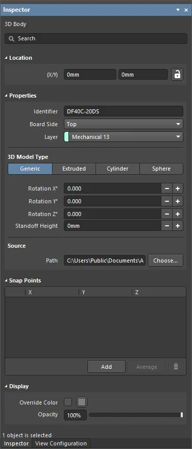
3D Body Properties
All 3D Body object properties are available for editing in the Inspector panel when a placed 3D Body is selected in the design space.
Location
- (X/Y)
- X (first field) - the current X (horizontal) coordinate of the reference point of the 3D Body, relative to the current design space origin. Edit to change the X position of the 3D Body. The value can be entered in either metric or imperial, include the units when entering a value whose units are not the current default.
- Y (second field) - The current Y (vertical) coordinate of the reference point of the 3D Body, relative to the current origin. Edit to change the Y position of the 3D Body. The value can be entered in either metric or imperial, include the units when entering a value whose units are not the current default.
Properties
- Identifier - enter a human-readable name used to identify the 3D Body object. Identifiers are useful for selecting a 3D body in the PCB panel.
- Board Side - use the drop-down to select from which side of the board the 3D Body will project. This setting is automatically changed if the 3D Body object is flipped to the other side of the board as part of a component flip.
- Layer - use the drop-down to select on which layer the 3D Body exists. Only layers that are currently enabled are available. If the chosen layer is paired, then when the body is flipped to the other side of the board as part of its component, it will also be moved to the paired layer.
3D Model Type
Select a model type for the 3D body object from the available options: Generic, Extruded, Cylinder, or Sphere. The options vary for each type and provide controls necessary for sizing and positioning in the 3D design space.
- Generic - when this option is chosen, the 3D Body object acts as a container for it and it is automatically resized to enclose the chosen model.
- Rotation X° - the angular rotation (in degrees) of the 3D model around the X-axis.
- Rotation Y° - the angular rotation (in degrees) of the 3D model around the Y-axis.
- Rotation Z° - the angular rotation (in degrees) of the 3D model around the Z-axis.
- Standoff Height - the distance from the board surface to the underside of the 3D model. Use a negative value for a model that must pass down through the PCB.
- Source
- Path - click Choose to search for and select the path of the STEP model (*.step, *.stp).
- Extruded
- Overall Height - the distance from the board surface to the top side of the extruded body.
- Standoff Height - the distance from the board surface to the underside of the extruded body. Use a negative value for extruded bodies that must pass down through the PCB.
- Texture
- Texture File - defines an image to be displayed on the top surface of the extruded body. Click
 to open a dialog to search for and select the desired file.
 - Center - the X and Y offsets that the center of the texture image will have with respect to the center of the top surface of the extruded body. For example, a value of 100mil, 0mil will shift the center point of the image 100mils in the X direction from the center point of the top surface of the extruded body.
- Size - the width (X-direction) and height (Y-direction) of the texture image. By default, the texture image will be uniformly scaled to fit the bounds of the top surface of the extruded body.
- Rotation - the rotation of the extruded body.
- Texture File - defines an image to be displayed on the top surface of the extruded body. Click
- Cylinder
- Height - the height of the cylindrical body.
- Radius - the radius of the cylindrical body.
- Rotation X° - the angular rotation (in degrees) of the cylindrical body around the X-axis.
- Rotation Y° - the angular rotation (in degrees) of the cylindrical body around the Y-axis.
- Rotation Z° - the angular rotation (in degrees) of the cylindrical body around the Z-axis.
- Standoff Height - the distance from the board surface to the underside of the cylindrical body. Use a negative value for a cylindrical body that must pass down through the PCB.
- Sphere
- Radius - the radius of the spherical body.
- Standoff Height - the distance from the board surface to the lowest edge of the spherical body. Use a negative value for a spherical body that must pass down through the PCB. You may use the (+/-) buttons to increase or decrease the standoff height by 1 mil.
Snap Points
- Grid region - displays the X, Y, and Z snap points for the sphere.
- Add - click to add a new snap point.
- Average - click to use the averages of all selected snap points for one individual snap point. This option is available only when two or more snap points are selected in the grid.
-
 - click to delete the selected snap point.
Display
- Override Color - enable if desired, then click the color box to access options to specify the object's color.
- Opacity - use the slider bar or enter the percentage directly to specify the transparency of the 3D body from invisible (left-most) to completely opaque (right-most).
This setting is a permanent setting for this object, however, it is also possible to adjust the object opacity temporarily in the PCB panel when it is set to 3D Models mode.
Component Body Manager Dialog
The Component Body Manager dialog provides controls to manage the 3D bodies for components interactively. It provides a central console with which to quickly modify 3D Body attributes.
The dialog can be accessed from the PCB and PCB library editors in the following ways.
- From the PCB Editor, right-click on a component in the PCB design space then select Component Actions » Manage 3D Bodies.
- From the PCB Library Editor, select Tools | 3D Body | Manage 3D Bodies.

The top region of the dialog lists each component footprint in the active library. In the actual design, this would be a list of all components on the board.
- Existing and Potential Component Bodies - lists all existing component bodies (3D Bodies) that are being used or could potentially be used for the component.
- Component bodies in: <ComponentDesignator> - shows the component's 2D footprint along with overlayed 3D Bodies whose Body State is currently set to In Component <ComponentDesignator>. The preview changes as bodies are included or excluded.
- Selected Body - shows the currently selected body in the list above. The title area for the window also reflects the body's description.
3D Body Placement Commands
The 3D Body Placement commands provide various means of altering 3D Body objects in order to suit the footprint.
These commands can be accessed from the PCB library editor by clicking Tools | 3D Body | 3D Body Placement.
- Add Snap Points From Vertices - used to add Snap Points to vertices of a chosen 3D Body. Snap points are used as reference markers on 3D objects and can be useful when orienting or aligning the 3D Body with primitives or other snap points on the PCB (or PCB 2D Footprint). After launching the command, the cursor will change to a cross-hair and you will be prompted to select the 3D model to which you want to add snap points.
- Remove Snap Points - used to remove Snap Points from vertices of a chosen 3D Body. After launching the command, the cursor will change to a cross-hair and you will be prompted to select the 3D model from which you wish to remove snap points.
- Orient And Position 3D Body - used to align a 3D Body with the PCB (e.g. the mechanical housing/enclosure), or 2D footprint, when viewing the current board/footprint in 3D. It uses 6 points to perform its function; three points selected on the 3D model and then three corresponding points picked on the board/footprint. After launching the command, the cursor will change to a cross-hair and you will be prompted to select the 3D model that you wish to position.
- Position 3D Body - used to align a 3D Body with the PCB (e.g. the mechanical housing/enclosure), or 2D footprint, when viewing the current board/footprint in 3D. It uses 2 points to perform its function; one selected on the 3D model and then one corresponding point picked on the board/footprint. After launching the command, the cursor will change to a cross-hair and you will be prompted to select the 3D model that you wish to position.
- Set Body Height - used to adjust the height of a chosen 3D Body relative to the top surface of the board/2D footprint. After launching the command, the cursor will change to a cross-hair and you will be prompted to select the 3D model that you wish to position.
- Measure Distances - used to measure distances between two points on the same chosen 3D Body, or between points between two different 3D bodies. After launching the command, the cursor will change to a cross-hair and you will be prompted to select the 3D model that you wish to start measuring from.
- Align Face With Board - used to position a chosen 3D Body so that its selected face is aligned with the surface of the board/2D footprint. After launching the command, the cursor will change to a cross-hair and you will be prompted to select the 3D model that you wish to align.
- Move Texture Location - used to modify the position of a texture object associated with a chosen extruded 3D Model. A texture file can be associated only with an extruded 3D model and allows an image to be displayed on that model's top surface - facilitating greater realism of your board when viewed in 3D. After launching the command, the cursor will change to blue cones (signifying 3D selection mode) and you will be prompted to select an extruded 3D Body that has a texture associated.