
Keepout
The Keepout command is used to place a keepout on the PCB or PCB library document. A keepout is the name given to an object that blocks or prevents the placement of copper objects within an area. The command can be accessed from the PCB and PCB library editors on the Keep-Out Layer in the following ways:
- From the PCB editor in the Home | Place | Keepout region. Choose the required keepout from the drop-down.

- From the PCB library editor in the Home | Place | More » Keepout region. Choose the required keepout from the sub-menu.

A keepout can be defined as a fence (in essence, a wall around the area to be protected) or it can be defined as a solid area of keepout that completely covers the area to be protected.
There are two approaches to defining a Keepout:
- All-layer keepout - place an object, such as a fill, arc or region, on the Keep-Out layer. The objects then create a keepout on all signal layers.
- Layer-specific keepout - place a layer-specific keepout object on a signal layer. This approach creates a keepout on only that signal layer. Layer-specific keepouts are not included in generated outputs such as Gerber or ODB++.
Each Keepout can be configured in the corresponding Inspector panel when the keepout is selected in the design space.
Arc Keepout
Arc Keepout

Location
- (X/Y)
- X (first field) - the current X (horizontal) coordinate of the reference point of the keepout, relative to the current design space origin. Edit to change the X position of the keepout. The value can be entered in either metric or imperial; include the units when entering a value whose units are not the current default.
- Y (second field) - The current Y (vertical) coordinate of the reference point of the keepout, relative to the current origin. Edit to change the Y position of the keepout. The value can be entered in either metric or imperial; include the units when entering a value whose units are not the current default.
Properties
- Restricted Layer - this field displays the restricted layer to which the keepout is currently assigned. To change the layer, click the field and select a layer from the drop-down list.
- Width - this field displays the width of the keepout line. Enter a different value for the width if required.
- Radius - this field displays the radius measured from the center point to the center of the keepout line. Enter a different value for the radius if required.
- Start Angle - this field displays the start angle of the keepout measured from the X-axis in the first quadrant (plane geometry). Enter a different value for the start angle if required.
- End Angle - this field displays the end angle of the keepout. Enter a different value for the end angle if required.
Fill Keepout
Fill Keepout

Location
- (X/Y)
- X (first field) - the current X (horizontal) coordinate of the reference point of the arc keepout, relative to the current design space origin. Edit to change the X position of the arc keepout. The value can be entered in either metric or imperial; include the units when entering a value whose units are not the current default.
- Y (second field) - The current Y (vertical) coordinate of the reference point of the arc keepout, relative to the current origin. Edit to change the Y position of the arc keepout. The value can be entered in either metric or imperial; include the units when entering a value whose units are not the current default.
- Rotation - the fill keepout's angle of rotation (in degrees), measured counterclockwise from zero (the 3 o'clock horizontal). Edit to change the rotation of the fill keepout. Minimum angular resolution is 0.001°.
Properties
- Restricted Layer - this field displays the restricted layer to which the keepout is currently assigned. To change the layer, click the field and select a layer from the drop-down list.
- Length - displays the current length of the keepout. Edit this field to change the length within the range 0.001mil to 10000mil.
- Width - displays the current width of the keepout. Edit this field to change the width within the range 0.001mil to 10000mil.
Solid Region Keepout
Solid Region Keepout
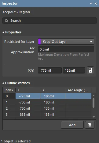
Properties
- Restricted Layer - this field displays the restricted layer to which the keepout is currently assigned. To change the layer, click the field and select a layer from the drop-down list.
- Arc Approximation - enter the maximum deviation from a perfect arc.
- (X/Y)
- X (first field) - the current X (horizontal) coordinate of the reference point of the keepout, relative to the current design space origin. Edit to change the X position of the keepout. The value can be entered in either metric or imperial; include the units when entering a value whose units are not the current default.
- Y (second field) - The current Y (vertical) coordinate of the reference point of the keepout, relative to the current origin. Edit to change the Y position of the keepout. The value can be entered in either metric or imperial; include the units when entering a value whose units are not the current default.
Outline Vertices
This region is used to modify the individual vertices of the currently selected object. You can modify the locations of existing vertices, add new vertices or remove them as required. Arc connections between vertex points can be defined, and support is also provided for exporting vertex information to and importing from a CSV-formatted file.
- Vertices Grid - lists all of the vertex points currently defined for the region in terms of:
- Index - the assigned index of the vertex (non-editable).
- X - the X (horizontal) coordinate for the vertex. Click to edit.
- Y - the Y (vertical) coordinate for the vertex. Click to edit.
- Arc Angle (Neg = CW) - the angle of an arc that is drawn to connect this vertex point to the next. By default, connections are straight-line edges, with this field remaining blank. Click to edit then enter an arc angle as required. Entry of a positive value will result in an arc drawn counterclockwise. To draw a clockwise arc, enter a negative value.
- Add - click to add a new vertex point. The new vertex will be added below the currently focused vertex entry and will initially have the same X,Y coordinates as the focused entry. Click
 to remove the currently selected vertex.
Track Keepout
Track Keepout

Location
- (X/Y)
- X (first field) - the current X (horizontal) coordinate of the reference point of the keepout, relative to the current design space origin. Edit to change the X position of the keepout. The value can be entered in either metric or imperial; include the units when entering a value whose units are not the current default.
- Y (second field) - The current Y (vertical) coordinate of the reference point of the keepout, relative to the current origin. Edit to change the Y position of the keepout. The value can be entered in either metric or imperial; include the units when entering a value whose units are not the current default.
Properties
- Restricted for Layer - use the drop-down to select the restricted layer.
- Start (X/Y) - displays the current X/Y coordinate of the keepout start point relative to the current origin.
- Width - displays the current width of the keepout. Edit this field to change the keepout width within the range 0.001mil to 10000mil.
- Length - displays the current length of the keepout. Edit this field to change the keepout length within the range 0.001mil to 10000mil.
- End (X/Y) - displays the current X/Y coordinate of the keepout end point, relative to the current origin.