
Directives
 A Generic No ERC, Differential Pair and Net Class directive
Design Directives are objects that are placed on the schematic during design capture, providing a way of specified instructions to be transferred to other parts of the software. A variety of Design Directives are available for use in the following two ways:
- Directives associated with the automatic compilation of source schematic documents.
- Directives used to pass information defined on a schematic sheet through to the PCB.

Generic No ERC
 Use No ERC markers to suppress error/warning messages about a specific node in the circuit. The No ERC marker is placed on a node in the circuit to suppress all reported warning and/or error violation conditions that are detected when the schematic project is compiled. Use this to deliberately limit error checking at a certain point in the circuit that you know will generate a warning (such as an unconnected pin), while still performing a comprehensive check of the rest of the circuit.
The No ERC marker supports a number of different styles and can be displayed in any color. Use this ability to reflect the design intent for this point in the circuit.

Choose a style that best reflects its function at that point in the circuit.
Generic No ERC directives are available for placement in the schematic editor in the following ways:
- Choose Home | Circuit Elements | Directives » Generic No ERC from the main menus.

- Right-click in the design space then click Place » Directives » Generic No ERC from the context menu.
After launching the command, the cursor will change to a cross-hair and you will enter placement mode:
- Position the cursor over a wire or other net object then click or press Enter to place a directive at that point in the circuit.
- Continue placing further No ERC markers or right-click or press Esc to exit placement mode.
Additional actions that can be performed during placement while the No ERC is still floating on the cursor are:
- Press the Tab key to pause the placement and open the Generic No ERC mode of the Inspector panel from where its properties can be changed on the fly. Click the design space pause button overlay (
 ) to resume placement.

The Inspector panel enables you to modify the properties of one or more design objects in the active document.

During placement, the No ERC mode of the Inspector panel can be accessed by pressing the Tab key. Once the No ERC is placed, all options appear.
After placement, the No ERC mode of the Inspector panel can be accessed in one of the following ways:
- Double-clicking on the placed No ERC object.
- Placing the cursor over the No ERC object, right-clicking then choosing Properties from the context menu.
Editing Multiple objects
The inspector panel supports multiple object editing, where the property settings that are identical in all currently selected objects may be modified. When multiples of the same object are selected manually in the design space, the Inspector panel field entry that is not shown as an asterisk (*) can be edited for all selected objects.
Generic No ERC Properties
Schematic Editor object properties are definable options that specify the visual style, content, and behavior of the placed object.
All No ERC properties are available for editing in the Inspector panel when a placed No ERC is selected in the design space.
Location
- (X/Y)
- X (first field) - the current X (horizontal) coordinate of the reference point of the object, relative to the current design space origin. Edit to change the X position of the object. The value can be entered in either metric or imperial; include the units when entering a value whose units are not the current default.
- Y (second field) - The current Y (vertical) coordinate of the reference point of the object, relative to the current origin. Edit to change the Y position of the object. The value can be entered in either metric or imperial; include the units when entering a value whose units are not the current default.
- Rotation - use the drop-down to select the rotation.
Properties
- Color - click on the colored box to access a drop-down from which you can select the default color.
- Symbol - use the drop-down to select the default from the available choices.
- Active - enable to make the primitive active.
Differential Pair

A Differential Pair is a design directive that allows design specifications to be associated with a net-type object within a schematic design. Differential pairs include the pre-defined parameter named DIFFPAIR which enables the software to recognize this and displays the object as a differential pair directive.
Differential Pairs are available for placement in the schematic editor in the following ways:
- Choose Home | Circuit Elements | Directives » Differential Pair from the main menus.

- Right-click in the design space then click Place » Directives » Differential Pair from the context menu.
A differential pair can be used to attach parameters to a Wire, Bus, Signal harness, and Sheet Symbol.
After launching the command, the cursor will change to a cross-hair and you will enter the design directive placement mode. Placement is made by performing the following actions:
- Position the cursor over a wire or other net object and click or press Enter to place.
- Continue placing further directives or right-click or press Esc to exit placement mode.
Additional actions that can be performed during placement – while the parameter set is still floating on the cursor are:
- Press the Tab key to pause the placement and access the Differential Pair mode of the Inspector panel, from where its properties can be changed on the fly. Click the design space pause button overlay ( ) to resume placement.
- Press the Alt key to constrain the direction of movement to the horizontal or vertical axis, depending on the initial direction of movement.
- Press the Spacebar to rotate counterclockwise or Shift+Spacebar for clockwise rotation. The action can also be performed while dragging the object. Rotation is in increments of 90°.
- Press the X or Y keys while in placement mode to flip the parameter set along the X-axis or Y-axis.
Graphical Editing
This method of editing allows you to select a placed parameter set directive directly in the design space and change its location or orientation graphically.
When a differential pair directive is selected in the design space, a dashed box will appear around the directive. The box encloses the area occupied by the directive only. For each visibility-enabled member parameter of the set, a dashed line will be visible, connecting the text field of the parameter to the body of the directive, which affirms association.
Click anywhere inside the dashed box then drag to reposition the differential pair as required. While dragging, the differential pair can be rotated (Spacebar/Shift+Spacebar) or mirrored (X or Y keys to mirror along the X-axis or Y-axis).
Non-Graphical Editing
This method of editing uses the Inspector panel mode to modify the properties of a differential pair object.
During placement, the Differential Pair mode of the inspector panel can be accessed by pressing the Tab key. Once the parameter set is placed, all options appear.
After placement, the Differential Pair mode of the Inspector panel can be accessed in one of the following ways:
- Double-clicking on the placed differential pair object.
- Placing the cursor over the differential pair object, right-clicking then choosing Properties from the context menu.
Editing Multiple objects
The inspector panel supports multiple object editing, where the property settings that are identical in all currently selected objects may be modified. When multiples of the same object are selected manually in the design space, the Inspector panel field entry that is not shown as an asterisk (*) can be edited for all selected objects.
Differential Pair Properties
Schematic Editor object properties are definable options that specify the visual style, content, and behavior of the placed object.
All Differential Pair properties are available for editing in the Inspector panel when a placed differential pair is selected in the design space.
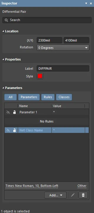
Location
- (X/Y)
- X (first field) - the current X (horizontal) coordinate of the reference point of the object, relative to the current design space origin. Edit to change the X position of the object. The value can be entered in either metric or imperial; include the units when entering a value whose units are not the current default.
- Y (second field) - The current Y (vertical) coordinate of the reference point of the object, relative to the current origin. Edit to change the Y position of the object. The value can be entered in either metric or imperial; include the units when entering a value whose units are not the current default.
- Rotation - use the drop-down to select the rotation. Choices are 0 Degrees, 90 Degrees, 180 Degrees, and 270 Degrees.
Properties
- Label - the differential pair label. Edit if desired.
- Style - use the drop-down to select the style: Large or Tiny. Click on the color box to access a drop-down from which you can select the default color.
Parameters
- Grid - lists the Name and Value of the parameters associated with the currently selected parameter. Once added, the Name and Value fields may be edited. The Value can be named by clicking on the field and entering the desired text. The Name field may only be changed when in the Inspector panel mode of the Differential Pair object, by using Ctrl+Click. This method opens the Parameter Inspector panel, where you may enter the desired name within the Name field. You may use the lock (
 ) icon to lock/unlock a listed parameter. You may use the hide (
  ) or (
 ) icon to show/hide the given parameter from within the Schematic editor. All parameters, individual parameters, or no parameters may be displayed within this region by toggling the All and individual parameter buttons. The parameters are disabled when their respective buttons are gray, and enabled when their respective buttons are blue.
 - Add - use the drop-down to add a type of class:
- Net Class - select to add a new net class.
- Diff. Pair Net Class - select to add a new differential pair net class.
- Parameter - select to add a new parameter class.
- Rule - click to open the Choose Design Rule Type dialog in which you can choose a new rule. After choosing a new design rule then clicking OK, the Edit PCB Rule (From Schematic) dialog opens so that you can edit the new rule, if desired.
Click the pencil ( ![]() ) icon to open the Edit PCB Rule (From Schematic ) dialog to edit the selected item. Click the bin (
) icon to open the Edit PCB Rule (From Schematic ) dialog to edit the selected item. Click the bin (  ) icon to delete the selected item.
 dialog when editing the Routing Corners design rule.") The Edit PCB Rule (From Schematic) dialog when editing the Routing Corners design rule.
The Edit PCB Rule (From Schematic) dialog when editing the Routing Corners design rule.
- Font Settings - click on the displayed font to change the font style. This option is only available once a net class, differential pair net class, parameter, or rule has been added.
- Other - If a net class, differential pair net class, parameter, or rule has been added, click to open a drop-down to change additional options:
- Show Parameter Name - enable to show the parameter name.
- Allow Synchronization with Database - enable to synchronize with the database.
- X/Y - enter the X and Y coordinates.
- Rotation - use the drop-down to select the rotation.
- Autoposition - check to enable auto-positioning.
Net Class

A Net Class is a design directive that allows design specifications to be associated with a net-type object within a schematic design. Net Classes are the default parameter set directives.
Net Classes are available for placement in the schematic editor in the following ways:
- Choose Home | Circuit Elements | Directives » Net Class from the main menus.

- Right-click in the design space then click Place » Directives » Net Class from the context menu.
A Net Class can be used to attach parameters to a Wire, Bus, Signal harness, and Sheet Symbol.
After launching the command, the cursor will change to a cross-hair and you will enter the design directive placement mode. Placement is made by performing the following actions:
- Position the cursor over a wire or other net object and click or press Enter to place.
- Continue placing further directives or right-click or press Esc to exit placement mode.
Additional actions that can be performed during placement while the parameter set is still floating on the cursor are:
- Press the Tab key to pause the placement and access the Net Class mode of the Inspector panel, from where its properties can be changed on the fly. Click the design space pause button overlay ( ) to resume placement.
- Press the Alt key to constrain the direction of movement to the horizontal or vertical axis, depending on the initial direction of movement.
- Press the Spacebar to rotate the arc counterclockwise or Shift+Spacebar for clockwise rotation. The action can also be performed while dragging the object. Rotation is in increments of 90°.
- Press the X or Y keys while in placement mode to flip the parameter set along the X-axis or Y-axis.
Graphical Editing
This method of editing allows you to select a placed parameter set directive directly in the design space and change its location or orientation graphically.
When a Net Class directive is selected in the design space, a dashed box will appear around the directive. The box encloses the area occupied by the directive only. For each visibility-enabled member parameter of the set, a dashed line will be visible, connecting the text field of the parameter to the body of the directive, which affirms association.
Click anywhere inside the dashed box then drag to reposition the Net Class as required. While dragging, the Net Class can be rotated (Spacebar/Shift+Spacebar) or mirrored (X or Y keys to mirror along the X-axis or Y-axis).
Non-Graphical Editing
This method of editing uses the Inspector panel mode to modify the properties of a Net Class object.

During placement, the Parameter Set mode of the inspector panel can be accessed by pressing the Tab key. Once the net class is placed, all options appear.
After placement, the Parameter Set mode of the Inspector panel can be accessed in one of the following ways:
- Double-click on the placed Net Class object.
- Place the cursor over the Net Class object, right-click then choose Properties from the context menu.
Editing Multiple objects
The inspector panel supports multiple object editing, where the property settings that are identical in all currently selected objects may be modified. When multiples of the same object are selected manually in the design space, the Inspector panel field entry that is not shown as an asterisk (*) can be edited for all selected objects.

Tips
- Net Class directives enable you to create user-defined net classes on the schematic. When a PCB is created from the schematic, the information in a Net Class directive is used to create the corresponding Net Class on the PCB. To make a net a member of a net class, attach a parameter set directive to the relevant wire or bus and a class whose name is set to the desired class. The Generate Net Classes option (for User-Defined Classes) must be enabled on the Class Generation tab of the Project Options dialog to use this feature.
- If a Net Class directive has been defined for a net, then any PCB design rules that are also created by that parameter set object will have a rule scope of Net Class, when the design is transferred to the PCB editor.
- A Net Class directive can be created from your placed Parameter Set directive by adding a class that must have its value set to the required PCB Net Class.
Net Class Properties
All Net Class properties are available for editing in the Inspector panel when a placed Net Class is selected in the design space.
Location
- (X/Y)
- X (first field) - the current X (horizontal) coordinate of the reference point of the object, relative to the current design space origin. Edit to change the X position of the object. The value can be entered in either metric or imperial; include the units when entering a value whose units are not the current default.
- Y (second field) - The current Y (vertical) coordinate of the reference point of the object, relative to the current origin. Edit to change the Y position of the object. The value can be entered in either metric or imperial; include the units when entering a value whose units are not the current default.
- Rotation - use the drop-down to select the rotation.
Properties
- Label - the Net Class label. Edit if desired.
- Style - use the drop-down to select the style: Large or Tiny. Click on the color box to access a drop-down from which you can select the default color.
Parameters
- Grid - lists the Name and Value of the parameters associated with the currently selected parameter. Once added, the Name and Value fields may be edited. The Value can be named by clicking on the field and entering the desired text. The Name field may only be changed when in the Inspector panel mode of the Net Class object, by using Ctrl+Click. This method opens the Parameter Inspector panel, where you may enter the desired name within the Name field. You may use the lock () icon to lock/unlock a listed parameter. You may use the hide ( ) or () icon to show/hide the given parameter from within the Schematic editor. All parameters, individual parameters, or no parameters may be displayed within this region by toggling the All and individual parameter buttons. The parameters are disabled when their respective buttons are gray, and enabled when their respective buttons are blue.
- Add - use the drop-down to add a type of class:
- Net Class - select to add a new net class.
- Diff. Pair Net Class - select to add a new differential pair net class.
- Parameter - select to add a new parameter class.
- Rule - click to open the Choose Design Rule Type dialog in which you can choose a new rule. After choosing a new design rule then clicking OK, the Edit PCB Rule (From Schematic) dialog opens so that you can edit the new rule if desired.
Click the pencil ( ![]() ) icon to open the Edit PCB Rule (From Schematic ) dialog to edit the selected item. Click the bin ( ) icon to delete the selected item.
) icon to open the Edit PCB Rule (From Schematic ) dialog to edit the selected item. Click the bin ( ) icon to delete the selected item.
The Edit PCB Rule (From Schematic) dialog when editing the Routing Corners design rule.
- Font Settings - click on the displayed font to change the font style. This option is only available once a net class, Net Class, parameter, or rule has been added.
- Other - If a net class, differential pair, parameter, or rule has been added, click to open a drop-down to change additional options.