
Harnesses
Harness Connector

A Harness Connector object is an electrical drawing primitive. It is essentially a container to group various signals together to form a Signal Harness including buses and wires. A Harness Connector is defined by the Harness Type.
Harness Connector Object
Harness Connectors are available for placement in the schematic editor only in one of the following ways:
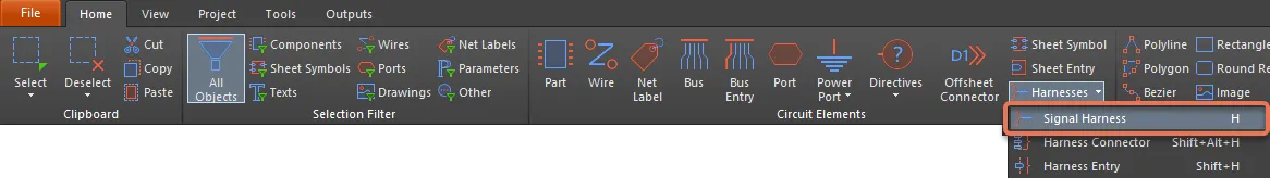
- Choose Home | Circuit Elements | Harnesses » Harness Connector from the main menus.

- Right-click in the design space then choose Place » Harness » Harness Connector from the context menu.
After launching the command, the cursor will change to a cross-hair and you will enter harness connector placement mode. Placement is made by performing the following sequence of actions:
- Click or press Enter to anchor the tip of the harness connector.
- Move the cursor to adjust the size of the harness connector, then click or press Enter to anchor the corner and complete placement of the harness connector.
- Continue to place other harness connectors or right-click or press Esc to exit placement mode.
Additional actions that can be performed during placement while the harness connector is still floating on the cursor and before its tip is anchored are:
- Press the Tab key to open the Inspector panel in which properties for the harness connector can be changed on the fly.
- Press the Alt key to constrain the direction of movement to the horizontal or vertical axis depending on the initial direction of movement.
- Press the Spacebar to rotate the harness connector counterclockwise or Shift+Spacebar for clockwise rotation. Rotation is in increments of 90°.
- Press the X or Y keys to mirror the harness connector along the X-axis or Y-axis respectively.
Graphical Editing
This method of editing allows you to select a placed harness connector object directly in the design space and change its size, shape or location graphically.
When a harness connector object is selected, the following editing handles are available:

- Click and drag A to resize the harness connector in the vertical and horizontal directions simultaneously.
- Click and drag B to resize the harness connector in the vertical and horizontal directions separately.
- Ctrl+click and drag C vertically to change the location of the harness connector's tip.
- Ctrl+click and drag C horizontally to resize the harness connector in the horizontal direction.
- Click anywhere on the harness connector away from editing handles then drag to reposition it. While dragging, the harness connector can be rotated (Spacebar/Shift+Spacebar) or mirrored (X or Y keys to mirror along the X-axis or Y-axis respectively).
- The Harness Connector Type text for a harness connector object can be edited in place by:
- Single-clicking the text to select it.
- Single-clicking again (or pressing the Enter key) to enter the in-place editing mode. Sufficient time between each click should be given to ensure the software does not interpret the two single-clicks as one double-click (which would open the harness connector type's properties dialog).
- To finish editing in-place text, press the Enter key, or use the mouse to click away from the text.
Non-Graphical Editing
This method of editing uses the Inspector panel mode to modify the properties of an object.

During placement, the Harness Connector mode of the Inspector panel can be accessed by pressing the Tab key. Once the object is placed, all options appear.
After placement, the Harness Connector mode of the Inspector panel can be accessed in one of the following ways:
- If the Inspector panel is already open, select the object, right-click then choose Properties from the context menu.
- With the object selected, choose View | Schematic | Inspector from the main ribbons.
Editing Multiple Objects
The Inspector panel supports multiple object editing in which the property settings that are identical in all currently selected objects may be modified. When multiples of the same object type are selected manually, an Inspector panel field entry that is not shown as an asterisk (*) may be edited for all selected objects.
Tips
- The Harness Type option in the Inspector panel defines the type of the Harness Connector. When a Harness Type is used within your project, the corresponding Harness Definition for this Harness Type is referenced.
- By default, newly-placed Harness Connectors are given the Harness Type Harness.
- The Harness Type can be hidden from view or moved to save space in your design. Toggle the eye icon associated with the Harness Type option in the panel. Alternatively, double-click on the Harness Type text (the text associated with the harness connector) then toggle the eye icon associated with the Value option in the Parameter mode of the Inspector panel.
Harness Connector Properties
All harness connector properties are available for editing in the Inspector panel when a placed harness connector is selected in the design space.
Location
- (X/Y)
- X (first field) - the current X (horizontal) coordinate of the reference point of the object, relative to the current design space origin. Edit to change the X position of the object. The value can be entered in either metric or imperial; include the units when entering a value whose units are not the current default.
- Y (second field) - The current Y (vertical) coordinate of the reference point of the object, relative to the current origin. Edit to change the Y position of the object. The value can be entered in either metric or imperial; include the units when entering a value whose units are not the current default.
- Rotation - use the drop-down to select the rotation.
Properties
- Harness Type - enter the name of the harness. Click the eye icon to show/hide the harness type. Click Harness Type to open the Inspector panel in Parameter mode to configure the harness connector type.

- Bus Text Style - use the drop-down to select the style: Full or Prefix.
- Width - the width, which may be edited.
- Height - the height, which may be edited.
- Primary Position - the primary position, which may be edited.
- Border - use the drop-down to select the default from the available choices: Smallest, Small, Medium, and Large. Click on the colored box to the right of the selections to access a drop-down from which you can select the default color.
- Fill - click on the colored box to access a drop-down from which you can select the default color.
Entries
Use this region to manage the connector's associated harness entries.
- Harness Entries Grid - the grid lists all of the harness entries currently defined for the harness connector.
- Add - click to add a new harness entry to the harness connector. The new entry will be added at the bottom of the list and given the default name of 0. Click
 to delete the currently selected entry from the grid.
 - Font - click on the displayed font to change the font style in various ways. This option is only available if there is at least one entry in the grid.
Harness Entry

A Harness Entry is an electrical design primitive that is placed within a Harness Connector. A Harness Entry is the connection point through which signals - through wires, buses, and other signal harnesses - are combined to form a higher level Signal Harness. Signal Harnesses enable the logical grouping of different signals for increased flexibility and streamlined design.
Harness Entry Object
Harness Entries are available for placement in the Schematic Editor in one of the following ways:
- Choose Home | Circuit Elements | Harnesses » Harness Entry from the main menus.

- Right-click in the design space then choose Place » Harness » Harness Entry from the context menu.
Harness entries can also be managed in the following non-graphical ways:
- Added/edited/removed as part of the Harness Connector definition in the Harness Connector mode of the Inspector panel.
- Added/edited/removed as part of the textual harness connector definition through a harness definition file (*.Harness). Such a defined harness connector can only be placed in the design using the Place » Harness » Predefined Harness Connector command available from the Schematic Editor's right-click context menu.
After launching the command, the cursor will change to a cross-hair and you will enter harness entry placement mode. Placement is made by performing the following sequence of actions:
- Move the harness entry attached to the cursor over a placed harness connector on the sheet.
- Adjust the position of the harness entry in relation to the edge of the harness connector, opposite the connector's tip, then click or press Enter to anchor the harness entry and complete placement.
- Continue placing further harness entries, or right-click or press Esc to exit placement mode.
While the harness entry is still floating on the cursor, and while it is within the bounds of a harness connector, press the Tab key to open the Parameter mode of the Inspector panel in which properties for the harness entry can be changed on-the-fly.
Graphical Editing
This method of editing allows you to select a placed harness entry object directly in the design space and change its location graphically.

A selected Harness Entry
- Click and drag to reposition the harness entry vertically along the edge of its parent harness connector as required.
- Hold Ctrl then click and drag the harness entry to move it from the current harness connector to another harness connector on the sheet. Once the harness entry has cleared the boundary of the source harness connector, the Ctrl key can be released.
- Clicking and dragging the sheet entry outside of the sheet symbol boundary will cause the sheet symbol to automatically resize to accommodate the entry's new location.
- The name text for a harness entry object can be edited in-place by:
- Single-clicking the harness entry to select it.
- Single-clicking again (or pressing the Enter key) to enter the in-place editing mode. Sufficient time between each click should be given to ensure the software does not interpret the two single-clicks as one double-click (which would open the harness entry's properties dialog).
- To finish editing in-place text, press the Enter key or use the mouse to click away from the harness entry.
Non-Graphical Editing
This method of editing uses the Inspector panel mode to modify the properties of an object.

During placement, the Harness Entry mode of the Inspector panel can be accessed by pressing the Tab key. Once the object is placed, all options appear.
After placement, the Harness Entry mode of the Inspector panel can be accessed in one of the following ways:
- If the Inspector panel is already open, select the object, right-click then choose Properties from the context menu.
- With the object selected, choose View | Schematic | Inspector from the main ribbons.
Editing Multiple Objects
The Inspector panel supports multiple object editing in which the property settings that are identical in all currently selected objects may be modified. When multiples of the same object type are selected manually, an Inspector panel field entry that is not shown as an asterisk (*) may be edited for all selected objects.
Tips
- A Harness Entry can be connected directly to a wire, bus or signal harness. The Harness Type field in the Harness Connector mode of the Inspector panel is used when nesting signal harnesses. The field will auto-populate with the Harness Type of the connected signal harness.
- If you need to negate (include a bar over the top of) a harness entry name, this can be done by including a backslash character after each character in the name (e.g., E\N\A\B\L\E\).
Harness Entry Properties
Schematic Editor object properties are definable options that specify the visual style, content and behavior of the placed object.
All object properties are available for editing in the Inspector panel when a placed object is selected in the design space.
Properties
- Harness Name - the name of the harness.
- Font - use the controls to select the font, font size, font color, and add any desired special characteristics to the font, such as bold, italics, and underlines.
Signal Harness

A Signal Harness is an electrical design primitive. It is an abstract connection that enables the logical grouping of different signals including buses, wires and other signal harnesses for increased flexibility and streamlined design. Signal Harnesses allow for the creation and manipulation of higher-level abstract connections between subcircuits in your PCB Projects. They allow for a more complex design within the same schematic design space, increasing the readability of designs and building potential for re-use.
Signal Harness Object
Signal Harnesses are available for placement in the Schematic Editor only in one of the following ways:
- Choose Home | Circuit Elements | Harnesses » Signal Harness from the main menus.
- Right-click in the design space then choose Place » Harness » Signal Harness from the context menu.
After launching the command, the cursor will change to a cross-hair and you will enter signal harness placement mode. Placement is made by performing the following sequence of actions:
- Click or press Enter to anchor the starting point for the signal harness.
- Position the cursor then click or press Enter to anchor a series of vertex points that define the shape of the signal harness.
- After placing the final vertex point, right-click or press Esc to complete placement of the signal harness.
- Continue placing further signal harness objects or right-click or press Esc to exit placement mode.
- Use the Backspace or Delete keys to remove the last harness segment placed.
When placing a signal harness there are three 'manual' placement modes, two of which have Start and End sub-modes. The mode specifies how corners are created when placing signal harnesses and the angles at which signal harnesses can be placed. During placement:
- Press Shift+Spacebar to cycle through the 90 Degree, 45 Degree and Any Angle modes.
- While in the 90 Degree or 45 Degree mode (known as true orthogonal modes), press Spacebar to cycle between the Start and End sub-modes.
- During placement, the current placement mode is displayed in the Status bar. You can change modes at any time during signal harness placement.
- In modes other than Any Angle, the line segment attached to the cursor is a look-ahead segment. The segment you are actually placing precedes this look-ahead segment.
 45 degree mode
 90 degree mode
 Any angle mode
Press Shift+Spacebar to cycle through the different placement modes.
Guided Wiring of a Signal Harness
Schematics have a definable electrical grid that makes it easy to define electrical connections between objects. As you are placing a Signal Harness, when the Signal Harness falls within the electrical grid range of another electrical object, the cursor will snap to the fixed object and a Hot Spot (blue cross) will appear.
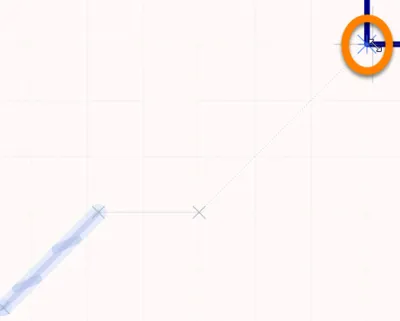
Hot Spot (blue cross)
The Hot Spot guides you to where a valid connection can be made and automatically snaps the cursor to electrical connection points.
The electrical grid can be defined on the General tab in the Inspector panel in Document Options mode (Project | Content | Document Options). It is recommended that you set the electrical grid to be slightly smaller than the current snap grid or it becomes difficult to position electrical objects one snap grid apart.
Graphical Editing
This method of editing allows you to select a placed signal harness object directly in the design space and change its size and/or shape graphically.
When a signal harness object is selected, the following editing handles are available:

Selected Signal Harness, ready for graphical editing
- Click and drag A to reposition the endpoints of the signal harness.
- Click and drag B to move a signal harness vertex. The endpoints will remain anchored.
- Ctrl+click and drag on a segment to grab that segment and reposition it. The endpoints and other vertices will remain anchored.
- Right-click on a vertex point and choose the Edit Signal Harness Vertex n command to open the Vertices region of the Signal Harness mode of the Inspector panel, with the entry for the
nthvertex selected ready for editing. - Ctrl+click and hold on a segment then press Insert on the keyboard to add a vertex at that point.
- Click and hold on a vertex then press Delete on the keyboard to remove that vertex.
Non-Graphical Editing
This method of editing uses the Inspector panel mode to modify the properties of an object.

During placement, the Signal Harness mode of the Inspector panel can be accessed by pressing the Tab key. Once the object is placed, all options appear.
After placement, the Signal Harness mode of the Inspector panel can be accessed in one of the following ways:
- If the Inspector panel is already open, select the object, right-click then choose Properties from the context menu.
- With the port selected, choose View | Schematic | Inspector from the main ribbons.
Editing Multiple Objects
The Inspector panel supports multiple object editing in which the property settings that are identical in all currently selected objects may be modified. When multiples of the same object type are selected manually, an Inspector panel field entry that is not shown as an asterisk (*) may be edited for all selected objects.
Signal Harness Properties
Schematic Editor object properties are definable options that specify the visual style, content and behavior of the placed object.
All object properties are available for editing in the Inspector panel when a placed object is selected in the design space.
Properties
- Width - use the drop-down to select the default width from the available choices: Smallest, Small, Medium, and Large. Click on the color box to access a drop-down from which you can select the default color.
Vertices
- Grid - lists all of the vertex points currently defined for the object in terms of:
- Index - the assigned index of the vertex (non-editable).
- X - the X (horizontal) coordinate for the vertex. Click to edit.
- Y - the Y (vertical) coordinate for the vertex. Click to edit.
- Add - click to add a new vertex point. The new vertex will be added below the currently focused vertex entry and will initially have the same X, Y coordinates as the focused entry. Click
 to remove the currently selected vertex.