
Sheet Symbol & Sheet Entry
Sheet Symbol
 A placed Sheet Symbol
A sheet symbol is an electrical design primitive. It is used to represent a sub-sheet in a multi-sheet hierarchical design. Sheet symbols include sheet entry symbols, which provide a connection point for signals between the parent and child sheets in a hierarchical design, similar to the way that Ports provide connections between sheets in a flat-sheet design.
Sheet Symbol Object
Sheet symbols are available for placement in the Schematic Editor in the following ways:
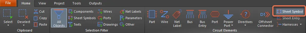
- Choose Home | Circuit Elements | Sheet Symbol from the main menus.
- Right-click in the design space then choose Place » Sheet Symbol from the context menu.
After launching the command, the cursor will change to a cross-hair and enter sheet symbol placement mode. Placement is made by performing the following actions:
- Click or press Enter to anchor the first corner of the sheet symbol.
- Move the cursor to adjust the size of the sheet symbol then click or press Enter to complete placement.
- Continue placing further sheet symbols or right-click or press Esc to exit placement mode.
Additional actions that can be performed during placement while the sheet symbol is still floating on the cursor and before its first corner is anchored are:
- Press the Tab key to access the Sheet Symbol mode of the Inspector panel from where properties for the sheet symbol can be changed on the fly. Click the design space pause button overlay (
 ) to resume placement overlay.
 - Press and hold the Alt key to constrain the direction of movement to the horizontal or vertical axis depending on the initial direction of movement.
- Press the Spacebar to rotate the sheet symbol counterclockwise or Shift+Spacebar for clockwise rotation. Rotation is in increments of 90°.
- Press the X or Y keys to mirror the sheet symbol along the X-axis or Y-axis.

Graphical Editing
This method of editing allows you to select a placed sheet symbol object directly in the design space and graphically change its size, shape, or location.
When a sheet symbol object is selected, you can click and drag the editing handles to resize the sheet symbol.
 A selected Sheet Symbol
Click anywhere on the sheet symbol away from editing handles and drag to reposition it. While dragging, the sheet symbol can be rotated (Spacebar/Shift+Spacebar) or mirrored (X or Y keys to mirror along the X-axis or Y-axis).
The sheet symbol's Designator and File Name text fields can only be resized by changing the size of the font used (accessed through the appropriate object's Inspector panels). As such, editing handles are not available when either of those objects are selected.
 Selected Designator and Filename for a sheet symbol
- Click anywhere inside the dashed box and drag to reposition the text object as required. While dragging, the text can be rotated (Spacebar/Shift+Spacebar) or mirrored (X or Y keys to mirror along the X-axis or Y-axis).
- The text for an object can be edited in-place by:
- Single-clicking the designator or filename text to select it.
- Single-clicking again (or pressing Enter) to enter the in-place editing mode. Sufficient time between each click should be given to ensure the software does not interpret the two single-clicks as one double-click (which would open the associated Inspector panel).
- To finish editing in-place text, press Enter or use the mouse to click away from the text object.
Non-Graphical Editing
This method of editing uses the Inspector panel mode to modify the properties of a Sheet Symbol object.
 During placement, the Sheet Symbol mode of the Inspector panel can be accessed by pressing the Tab key. Once the Sheet Symbol is placed, all options appear.
After placement, the Sheet Symbol mode of the Inspector panel can be accessed in one of the following ways:
- If the Inspector panel is already open, select the Sheet Symbol object.
- With the Sheet Symbol selected, choose View | Schematic | Inspector from the main ribbons.
Editing Multiple objects
The Inspector panel supports multiple object editing in which the property settings that are identical in all currently selected objects may be modified. When multiples of the same object type are selected manually, an Inspector panel field entry that is not shown as an asterisk (*) may be edited for all selected objects.
Sheet Symbol Actions
Formatting Designator and File Name
The sheet symbol Designator and File Name fields can be formatted independently of the sheet symbol.
Right-click Sheet Symbol Commands
Right-click over a placed sheet symbol to access a context-sensitive menu, from which the following commands are available (on the Sheet Symbol Actions sub-menu) that act on that sheet symbol (or all currently selected sheet symbols, where applicable).
 The Sheet Symbol Actions sub-menu
- Open SubSheet "<SheetName.SchDoc>" - use to access the child sheet referenced by the symbol, which will be opened (if not already) and made the active document in the main design window.
- Create Sheet From Sheet Symbol - use to create a new schematic document from the sheet symbol and add ports to that document corresponding to each of the sheet entries on the symbol. In this way, you can automatically create the sub-sheets for a multi-sheet schematic design based on the sheet symbols you have created and placed on the top sheet.
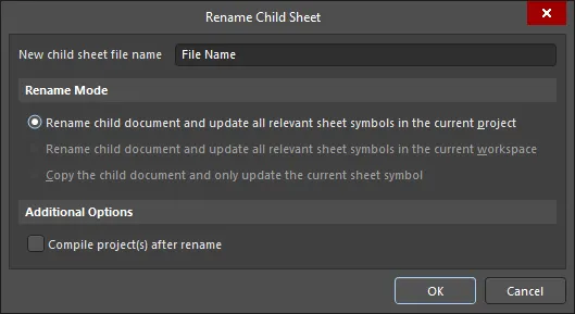
- Rename Child Sheet - use to quickly rename the child schematic sheet referenced by the sheet symbol. The Rename Child Sheet dialog will open in which you can specify the new name for the document as required, as well as the scope of the renaming action.
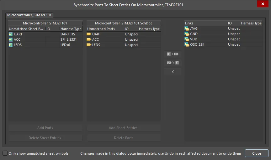
- Synchronize Sheet Entries and Ports - use to synchronize the sheet entries and sub-sheet ports for the sheet symbol. The Synchronize Ports To Sheet Entries dialog will open. Use this dialog to ensure that all sheet entries on the sheet symbol are matched to ports on the referenced child sheet below, both in terms of name and I/O Type.
- Flip Sheet Symbol Along X - use to flip the sheet symbol along the X-axis. The sheet entries associated with the symbol will essentially be swapped to the opposite side of the symbol (in the horizontal plane). Those on the left will be repositioned on the right and vice-versa.
 Example of flipping a sheet symbol along the X-axis
- Flip Sheet Symbol Along Y - use to flip the sheet symbol along the Y-axis. The sheet entries associated with the symbol will essentially be swapped to the opposite side of the symbol (in the vertical plane). Those at the top will be repositioned at the bottom and vice-versa.
 Example of flipping a sheet symbol along the Y-axis
- Toggle All Sheet Entries IO Type in Sheet Symbol - use to toggle the I/O Type for all sheet entries in the sheet symbol simultaneously where applicable.
 Example result of toggling sheet entry I/O
The actual change depends on the current PortIO Type as follows:
- Unspecified remains Unspecified.
- Output changes to Input.
- Input changes to Output.
- Bidirectional remains Bidirectional.
Tips
- If a group of sheet entries is pasted into a selected sheet symbol and those entries fall outside the current bounds of the symbol, it will automatically be resized to accommodate them.
- By using sheet symbol instantiation, multiple channels on the same sub-sheet can be referenced from a single sheet symbol. The syntax used involves the use of the Repeat keyword in the sheet symbol's Designator field and takes the form:
Repeat(SheetSymbolDesignator, FirstInstance, LastInstance), where SheetSymbolDesignator is the base name for the sheet symbol and FirstInstance and LastInstance together define the number of channels to be instantiated. The FirstInstance parameter must start at a value of one (1). - Multiple sub-sheets may be referenced by a single sheet symbol. Separate each filename by a semi-colon in the File Name field. With the effective use of off-sheet connectors placed on the sub-sheets, you can spread a section of your design over multiple sheets treating them as though they are one giant (flat) sheet. Note, however, that use of off-sheet connectors is only possible for sheets referenced by the same sheet symbol.
Sheet Symbol Properties
All Sheet Symbol object properties are available for editing in the Inspector panel when a placed Sheet Symbol is selected in the design space.
General Tab
- (X/Y)
- X (first field) - the current X (horizontal) coordinate of the reference point of the object, relative to the current design space origin. Edit to change the X position of the object. The value can be entered in either metric or imperial; include the units when entering a value whose units are not the current default.
- Y (second field) - The current Y (vertical) coordinate of the reference point of the object, relative to the current origin. Edit to change the Y position of the object. The value can be entered in either metric or imperial; include the units when entering a value whose units are not the current default.
Properties
- Designator - the current name for the sheet symbol. This field is used to provide the sheet symbol with a meaningful name that will distinguish it from other sheet symbols placed on the same schematic sheet. Typically the name will reflect the overall function of the schematic sub-sheet that the symbol represents. Toggle
 or
or  to show/hide the designator.
 - File Name - the current schematic document referenced by the sheet symbol. Toggle or to show/hide the file name.
- Bus Text Style - use the drop-down to select the style of the bus text. Choices are Full or Prefix.
- Width - enter the width, which may be edited.
- Height - enter the height, which may be edited.
- Line Style - use the drop-down to select the default from the available choices: Smallest, Small, Medium, and Large. Click on the color box to access a drop-down from which you can select the default line color.
- Fill Color - check to enable fills. Click on the color box to access a drop-down from which you can select the default fill color.
Source
- Local / Device / Managed - the source of the file.
- File Name - displays the current schematic document referenced by the sheet symbol. It is this field that provides the link between the sheet symbol and the schematic sub-sheet that the symbol represents. Click
 to open the Choose Document to Reference dialog to choose the required target sub-sheet. The dialog presents a listing of all source schematic sheets in the project (with the exception of the sheet upon which the symbol is currently placed).
- File Name - displays the current schematic document referenced by the sheet symbol. It is this field that provides the link between the sheet symbol and the schematic sub-sheet that the symbol represents. Click

Sheet Entries
- Grid - lists the Name and PortIO Type of all of the sheet entries currently defined for the sheet symbol. When there are sheet entries in the grid, the following additional options are available when an entry is selected:
- Font - click to configure the font style of the sheet entry.
- Other - click to open a drop-down to change additional options:
- Kind - use the drop-down to select the kind of sheet entry. Choices are: Block & Triangle, Triangle, Arrow, and Arrow Tail.
- Border Color - click to access controls to choose the border color.
- Fill Color - click to access controls to choose the fill color.
- Add - click the Add button to add a sheet entry. Use the
 button to delete a selected entry from the table.
Parameters Tab

Parameters
- Grid - lists the Name and Value of all of the parameters currently defined for the sheet symbol. When there are parameters in the grid, the following additional options are available when a parameter is selected:
- Font - click to configure the font style of the parameter.
- Other - click to open a drop-down to change additional options:
- Show Parameter Name - enable to show the parameter name in the design space.
- Allow Synchronization with Database - enable to synchronize with the database. This option is used to control if the comment can be updated. By default, these options are enabled to always allow synchronization with the source library/database. You may disable this option to prevent that comment from being included in an update process.
- X/Y - enter the X and Y coordinates desired.
- Rotation - use the drop-down to select the rotation.
- Autoposition - check to enable auto-positioning, meaning that the text will remain in the chosen position as the component is moved and rotated.
- Add - click the Add button to add a parameter. Use to delete a selected entry from the table.
Sheet Entry
 A placed Sheet Entry
A sheet entry is an electrical design primitive that belongs within a sheet symbol. It is placed within a sheet symbol to designate input/output ports for the symbol. The sheet entries correspond to ports placed in the source schematic sub-sheet that the symbol represents.
Sheet Entry Object
Sheet Entries are available for placement in the schematic editor only in the following ways:
- Choose Home | Circuit Elements | Sheet Entry from the main menus.

- Right-click in the design space then choose Place » Sheet Entry from the context menu.
After launching the command, the cursor will change to a cross-hair and you will enter sheet entry placement mode. Placement is made by performing the following sequence of actions:
- Move the sheet entry attached to the cursor over a placed sheet symbol on the sheet.
- Adjust the position of the sheet entry in relation to an edge of the sheet symbol, then click or press Enter to anchor the sheet entry to the required edge and complete placement.
- Continue placing further sheet entries or right-click or press Esc to exit placement mode.
Graphical Editing
This method of editing allows you to select a placed sheet entry object directly in the design space and change its location graphically.
Sheet entries can only be adjusted with respect to their shape by changing their I/O Type in the Inspector panel. As such, editing handles are not available when the Sheet Entry object is selected.
 A selected Sheet Entry
- Click and drag to reposition the sheet entry within its parent sheet symbol as required.
- Hold Ctrl then click and drag the sheet entry to move it from the current sheet symbol to another sheet symbol on the sheet. Once the sheet entry has cleared the boundary of the source sheet symbol, the Ctrl key can be released.
- Clicking and dragging the sheet entry outside of the sheet symbol boundary will cause the sheet symbol to automatically resize to accommodate the entry's new location.
Non-Graphical Editing
This method of editing uses the Inspector panel mode to modify the properties of a sheet entry object.
 During placement, the Sheet Entry mode of the Inspector panel can be accessed by pressing the Tab key. Once the Sheet Symbol is placed, all options appear.
After placement, the Sheet Entry mode of the Inspector panel can be accessed in one of the following ways:
- If the Inspector panel is already open, select the Sheet Symbol object.
- With the Sheet Symbol selected, choose View | Schematic | Inspector from the main ribbons.
Right-click Sheet Entry Actions
Right-click over a placed sheet entry to pop-up a context-sensitive menu, from which the following commands are available (on the Sheet Entry Actions sub-menu) that act on that sheet entry (or all currently selected sheet entries, where applicable):
- Toggle Sheet Entry IO Type - use this command to toggle the I/O Type for the sheet entry. It is also available by clicking Edit » Move » Toggle Sheet Entry IO Type from the main menus.
 Example of toggling sheet entry IO Type
The actual change depends on the current I/O Type as follows:
- Unspecified remains Unspecified.
- Output changes to Input.
- Input changes to Output.
- Bidirectional remains Bidirectional.
- Swap Sheet Entry Side - use to relocate the sheet entry to the directly opposite side of its parent sheet symbol. The sheet entry's I/O Type is not changed by the swap. It is also available by clicking Edit » Move » Swap Sheet Entry Side from the main menus.
 Example of swapping sheet entry side.
Tips
- When a Sheet Entry is connected to a Signal Harness, the Sheet Entry becomes a Harness object. By default, the Sheet Entry will change color to match the color of the Signal Harness.
- When a Sheet Entry is connected to a Harness Connector by a Signal Harness, the Harness Type in the Inspector panel is automatically populated with the Harness Type of the Harness Connector. When a Sheet Entry is connected to a Port by a Signal Harness and the Port has a Harness Type declared, the Sheet Entry will become a Harness object and change to the color of the Signal Harness. If you move the Sheet Entry away from the Harness Connector and the Harness Type field is not populated, the Sheet Entry will revert back to the default color.
- Should you need to negate (include a bar over the top of) a sheet entry name, this can be done by including a backslash character after each character in the name (e.g., E\N\A\B\L\E\).
- When instantiating multiple channels from the same sheet symbol, certain signals are repeated and sent individually to each instantiated channel. With respect to a sheet entry, a signal is repeated by using the Repeat keyword in the sheet entry's name (e.g., Repeat(Headphone)). The sheet entry is then wired to a bus, which in turn carries the individual signals to their correspondingly instantiated destinations.
Sheet Entry Properties
Schematic Editor object properties are definable options that specify the visual style, content, and behavior of the placed object.
All Sheet Entry object properties are available for editing in the Inspector panel when a placed Sheet Entry is selected in the design space.

Properties
- Name - the name of the sheet entry.
- I/O Type - use the drop-down to select the I/O type for the sheet entry. Choices include Unspecified, Output, Input, and Bidirectional.
- Harness Type - use the drop-down to select the type of harness.
- Font - use the controls to select the font, font size, font color, and add any desired special characteristics to the font, such as bold, italics, and underlining.
- Kind - use the drop-down to select the kind of text.
- Border Color - click the color box to access controls to select the border color.
- Fill Color - click the color box to access controls to select the border color.