Accessing the ECAD-MCAD Harness Sync Capabilities
- For the 3.8 CoDesigner update, the Harness Sync functionality moves from Focused Beta to Open Beta. Open Beta makes the functionality available to all designers with a suitable license, feedback can be sent to the development team via the MCAD CoDesigner forum.
- Refer to the Note in the right-hand pane for information on whether Harness Synchronization will be available in your installation of MCAD CoDesigner.
- Harness synchronization is currently available for PTC Creo and SOLIDWORKS, support for other MCADs will be added in future updates.
- In SOLIDWORKS, you need SOLIDWORKS Routing Electrical (included in the SOLIDWORKS Premium package) to be able to synchronize the harness. Please note that SOLIDWORKS Routing Electrical requires Microsoft Excel to be installed to be able to read the harness connectivity information.
Many electronic devices are built as an assembly of multiple circuit boards, cleverly shaped and arranged within a mechanical enclosure to deliver an aesthetic and useful product. Altium's electronic design (ECAD) software supports this, where multiple PCBs can be brought together to create an assembly of PCBs, called a Multi-Board Assembly. This assembly can also include the enclosure, other mechanical elements that make up the product, and the wiring harness that connects the PCBs within the enclosure.
CoDesigner 3.6 added support for synchronizing Harness Projects between Altium Designer and SOLIDWORKS, building on the existing support for PTC Creo that was introduced in CoDesigner 3.5. This page outlines the support for synchronizing Harness Projects, to learn more about synchronizing Multi-board assemblies, refer to the Synchronizing a Multi-board Assembly page.
- From ECAD, CoDesigner sends the following information about the Harness to MCAD:
- Connectors,
- Splices,
- Connectivity ("from-to" data), and
- Harness Topology (connection points with the sets of wires and cables going through those points).
- From MCAD, CoDesigner sends the results of 3D Harness routing back to the ECAD Harness Layout Drawing, including:
- The physical length of wires, cables, and harness segments.
- The 3D model of the Harness can also be sent to ECAD during Multiboard Assembly synchronization, along with the mechanical enclosure parts.
CoDesigner does not build the Harness Topology in ECAD's Layout Drawing after synchronizing back from MCAD, so the Harness Topology should be specified in that document before back synchronization.
MCAD CoDesigner Harness Capabilities
Transferring the Connectivity Information
- CoDesigner transfers the connectivity information (standard From-To information) from ECAD to MCAD.
- In PTC Creo, CoDesigner creates the corresponding Spool entities for each wire/cable according to the connectivity info. Note that these Spools are not reused, this is planned to be implemented in a future update.
- In SOLIDWORKS, CoDesigner creates the corresponding entities (records) in the Routing Library for each wire/cable, according to the connectivity information. These entities are not reused, this is planned to be implemented in a future update.
Wire/Cable Properties
- CoDesigner uses the following ECAD parameters to configure the corresponding wire/cable properties in MCAD:
- Thickness / THICKNESS
If it is not set in ECAD, MCAD CoDesigner sets the THICKNESS of wires to 1 mm and cables to 3 mm.
- Min. Bending Radius / MIN_BEND_RADIUS
If it is not set in ECAD, MCAD CoDesigner sets the MIN_BEND_RADIUS for wires to 1 mm and cables to 3 mm.
- Color / COLOR
If it is not set in ECAD, the default MCAD color is used.
- Units / UNITS (MM / INCH)
If it is not set in ECAD, CoDesigner will consider the values to be in MM
- If Units are not set in ECAD AND one of these two parameters - Thickness or Min Bending Radius - is also not set in ECAD (or can’t be read by CoDesigner), CoDesigner will set the default values for both the Thickness and Min Bend Radius parameters.
- In SOLIDWORKS, CoDesigner assigns the properties mentioned above.
- In PTC Creo, CoDesigner assigns those properties, as well as transferring all other properties defined in ECAD.
Connectors
- As it is not possible to define the physical pins in ECAD (at the moment), those pins should be specified in MCAD by changing the default pins created by CoDesigner (see below). Additionally, in PTC Creo, you can prepare the models with the pins beforehand, and use them through the native ECAD-MCAD component linkage feature.
- If native ECAD-MCAD component linkage is not used:
- If there are models stored for connectors in the ECAD library, they will be transferred to MCAD. If not, CoDesigner builds the dummy empty models in MCAD.
- In SOLIDWORKS, those models are registered in the Routing Library.
- For newly transferred connectors (the connectors that were not found in the harness project folder or in the MCAD common component folder), CoDesigner builds the dummy physical pins in MCAD:
- In PTC Creo: the entire set of pins (wire entry ports) according to the ECAD’s pinning, plus an additional cable entry port.
- In SOLIDWORKS: one connection point for a connector.
- The mechanical engineer can reorient those dummy pins in the models (and also build the models themselves in the situation where dummy empty models have been used).
- In SOLIDWORKS, if the models are stored in the common component folder, they will be reused. In PTC Creo, they are always reused.
- In MCAD, CoDesigner assigns the reference designators for the connectors according to what has been assigned in ECAD.
At this stage, only numeric pin designators can be synchronized from ECAD to MCAD. This will be improved in a future update.
Splices
- PTC Creo: Splices are represented by Parts with the entry ports created according to the set of wires connected in there. The mechanical engineer will need to change the orientation of entry ports in splices according to the 3D layout of the harness.
- SOLIDWORKS: Splices are represented by Parts with the connection points created according to the set of wires connected in there. The mechanical engineer will need to change the orientation of connection points in splices according to the 3D layout of the harness.
- In MCAD, CoDesigner assigns the reference designators for the splices according to what has been assigned in ECAD.
Twists
CoDesigner 3.7 (and later) synchronizes Twisted Pairs with MCAD as Cables, and calculates the physical length of wires considering the Twists per Unit Length and Thickness properties defined in the ECAD Twist object.
 The Twists per Unit Length and Thickness are defined as parameters of the ECAD harness Twist object.
The untwisted length of each wire is calculated as:

Wire Length (untwisted) = Turn Length x Number of Turns
where:
Number of Turns = Twists per Unit Length * Cable Length
Twists per Unit Length = number of twists per unit length of cable, defined as a parameter of the ECAD Twist object
Turn Length = sqrt((Twist Pitch)^2 + (pi*Thickness)^2)
Twist Pitch = 1 / Twists per Unit LengthThickness = outer diameter of the twisted pair, defined as a parameter of the ECAD Twist object
ECAD Connection Points and Harness Topology
In PTC Creo
- CoDesigner creates Datum Point entities that correspond to ECAD’s connection points (except for the ECAD’s connection points for Connectors).
- CoDesigner then does the initial physical routing of wires/cables using those points as Location Points.
- The mechanical engineer can place those points anywhere in the product assembly and create new location points for passing the wires/cables.
- It is not recommended to delete the connection points transferred from ECAD as they define the harness topology. If such a point is deleted, CoDesigner will try to restore it on the next sync (in the default position in space). However, it can result in errors in some circumstances.
- The mechanical engineer can delete and then recreate the physical wires/cables, or, create a Network and then pass physical wires/cables along it. However, the network and wires/cables should still go through the connection points transferred from ECAD in order not to break the harness topology specified in ECAD.
In SOLIDWORKS
- For each ECAD connection point (except for the ECAD connection point for each Connector), CoDesigner creates a Line of 1 mm length within the 3D route sketch.
- It’s not recommended to delete the connection points transferred from ECAD as they are defining the harness topology. If such a point is deleted, CoDesigner will try to restore it on the next sync, however, it can bring errors in some circumstances.
Physical Routing
In SOLIDWORKS
- Right after getting the initial harness design from ECAD, it's recommended to look into the 3D route sketch created by CoDesigner and clarify where the positions of connection points are, comparing that sketch with the 2D harness topology defined in ECAD's Layout Drawing. Clarity with the topology in 3D sketch will help you to construct the 3D route properly.
- In some cases, the transitions between the segments in the 3D routing sketch created by CoDesigner are not smooth (the tangency can not be set up correctly). Also, sometimes, SOLIDWORKS can not route some of the physical wires through the 3D routing sketch built by CoDesigner (for example, if there are several routes between two connectors in the sketch, SOLIDWORKS will route the physical wires/cables through the shortest one). These issues can be easily fixed by the user (keeping in mind the importance of connection points transferred from ECAD).
For editing 3D splines in SOLIDWORKS, it is recommended to enable the Enable spline tangency and curvature handles option in the SOLIDWORKS System Options dialog. (show image)
MCAD CoDesigner Harness Workflow
In ECAD, the harness is designed as a Harness project. This can be a stand-alone Harness project, or, the Harness project can be created as a child of a Multi-board Assembly project, along with linked PCB projects.
ECAD - Capture the Harness Wiring Diagram
The ECAD harness is captured as a Harness Design project (*.PrjHar). The logical representation of the harness is captured as a Harness Wiring Diagram (*.WirDoc). If the Harness is a child of a Multi-board Assembly project, the parts and connectivity that make up the Harness can be imported from the parent multi-board schematic if each Harness Entry on that schematic has a suitable Workspace Part defined, and the Mated Parts/Pins configured.
|
|
If the Harness is a child of a Multi-board Assembly, the Harness Components and connectivity specified in the parent Multi-board schematic can be loaded directly into the Harness Wiring Diagram editor (Design » Import Changes). If there is no parent Multi-board Assembly, place the Harness connector Parts from your Workspace using the Place » Part command. Learn more about Creating a Harness Wiring Component.
If you are importing the Harness from a Multi-board Assembly and the Harness entry connectors and the Mated Parts/Pins are defined on the Multi-board schematic, the Harness connectors will be placed with logical netlines joining the connected pins. These are not editable objects, and they are automatically replaced as you interactively wire the Harness.
Place wires/cables between the connector pins to replace the logical netlines and define the physical connections. Configure the properties of each wire, including THICKNESS, MIN_BEND_RADIUS and COLOR (as shown above), and the Harness is ready for layout. Learn more about Creating the Wiring Diagram.
|
ECAD - Transfer to Harness Layout Drawing
The physical structure of the ECAD Harness is defined in a Harness Layout Drawing (*.LdrDoc). The Harness Layout Drawing includes the topology of the harness, and MCAD integration (CoDesigner Push-Pull) is done from the Layout Drawing. As long as the connectors are present on the Harness Layout Drawing, the ECAD engineer can Push to MCAD, and the MCAD engineer can then do the 3D cable routing in MCAD.
|
|
Add a Harness Layout Drawing to the Harness project, and select Design » Import Wiring Diagram to import the Harness Wiring Diagram. Learn more about Importing the Harness Wiring.
This is the minimum state required for starting MCAD harness integration. The following steps are recommended, but technically not required to make a start.
Define Connection Points (points in space where the harness definition changes), and place a Harness Bundle between each pair of Connection Points. Learn more about Defining the Physical Harness Arrangement.
The default display for the connectors is to show their Graphical Symbol. Use the controls in the Model region of the Properties panel to change to a Physical Model, and then configure how that model is viewed in the Views region of the panel.
Open the MCAD CoDesigner panel, where the defined Harness can be Pushed to the Workspace, ready to be Pulled into MCAD.
|
MCAD - Create the Device Assembly
If the Harness is being designed as part of the MCAD device assembly, a few steps are required in MCAD to link the ECAD and MCAD assemblies.
- Open (or create) the MCAD device assembly.
- If there is a corresponding Multi-board Assembly project in ECAD, click the Link Multiboard button in the Altium CoDesigner panel and select the pushed ECAD Multi-board Assembly project. This action links the ECAD and MCAD assemblies. If your MCAD assembly already includes a PCB, then the Link Multiboard button will not be available in the panel. Instead, you use the Link Multiboard command in the dropdown menu at the top of the Altium CoDesigner panel (show image
![]() ).
).
- In a linked assembly, CoDesigner will automatically recognize each PCB. Other mechanical parts can also be transferred from MCAD to ECAD by nominating them as belonging to the device enclosure. For example, if your assembly currently includes the product enclosure, select that part/assembly in the MCAD model tree, then in the Altium CoDesigner ribbon, click the Enclosure button. Note that any number of MCAD parts or sub-assemblies can be included as part of the enclosure, including the Harness assembly and the Harness mounting clips.
- Place the MCAD assembly for each PCB into the MCAD device assembly.
The MCAD device assembly is now ready to add the Harness.
PTC Creo - Create the Harness Assembly
SOLIDWORKS - Create the Harness Assembly
- From the Altium CoDesigner panel in SOLIDWORKS, open the Altium CoDesigner Settings dialog and confirm that the Common folder for storing models that are coming from ECAD has been configured (show image
![]() ).
).
- Using the Altium CoDesigner panel in SOLIDWORKS, Pull the ECAD harness design from the Workspace.
- The ECAD component models will be used for the connectors, stored in the Common folder just specified.
- Each connector is placed with its connection point in a default location and orientation, relative to the origin of that model.
-
Confirm the location and orientation of the connection point, and update if required.Expand折りたたむ
|
|
Edit the connector to reposition and reorient the connection point. There is no need to perform feature recognition.
Edit the sketch plane that the connection point is defined on.
And change it to use the rear face of the connector.
Next, edit the sketch to relocate the connection point.
The center of the connector is a suitable location.
Edit the connection point to redefine its orientation.
Setting it perpendicular to the rear face of the connector.
Save the connector, and return to the harness assembly.
|
- After updating all of the connectors, SOLIDWORKS may show an assembly error because it cannot resolve the cable geometries. (show image
![]() )
)
-
This can be resolved by changing the routing sketch or by deleting the Harness, and Pulling it from the Workspace again. This time CoDesigner will use the updated connectors to build the harness in SOLIDWORKS, as shown below.
-
When you edit and save a component footprint in ECAD, a new revision of that component is created, so any changes made to the component's connection point in MCAD will be lost. ECAD component parameters can be edited without impacting the harness design in MCAD.
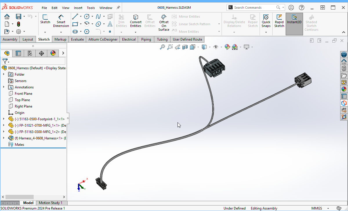 The Harness in SOLIDWORKS, with the connectors correctly oriented.
How the Electrical Cables and Components are Managed in SOLIDWORKS
SOLIDWORKS manages harness elements, such as wires and components, in the Routing Library Manager, as shown below.
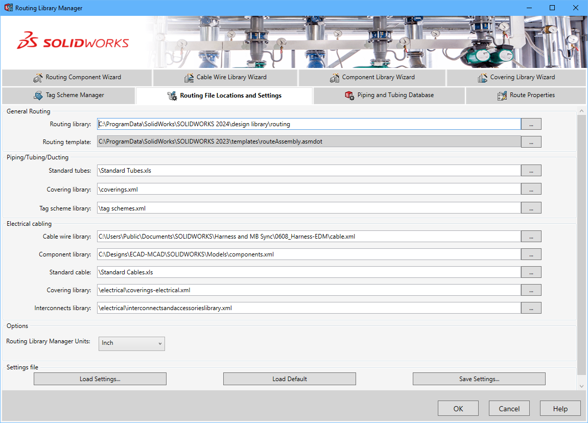
- With this release of Harness support, CoDesigner stores the Cable wire library locally for each project, so they cannot be reused across projects.
- By configuring the CoDesigner Common folder for storing models that are coming from ECAD setting you define a shared Component library, which can be a shared network location if required.
- At this stage, CoDesigner for SOLIDWORKS does not support linking native ECAD and MCAD components for Harness synchronization, this is to be resolved in a future update.
PTC Creo - Shape the Harness in the Device Assembly
The Cabling feature in Creo is accessed via the Applications ribbon; if it is not visible, enable it in the Customize - Ribbon page of the Creo Parametric Options dialog.
- Insert the harness into the MCAD device assembly.
- Mate each Harness connector with the corresponding PCB connector, or position it as a standalone component. Fully constrain each connector so that it remains mated if the PCB or standalone component is moved in the MCAD assembly, or if the PCB connector is moved on the PCB in ECAD. Note that the wiring does not update as connectors are moved, perform a Regenerate in Creo to resolve this.
- If mounting devices, such as clips, are being used to secure the harness, place these as required.
- If required, place additional Datum Points in the 3D space to use as references for the path of the physical harness routing. For example, a datum point can be added and referenced off each connector, this can be used to define the direction that the harness approaches each connector.
-
Route the wires and cables using the MCAD capabilities.
- A Routing Network can be created and used for the routing.
- Physical wires can be deleted and then recreated manually (for example, after creating a routing network) using the logical connectivity information saved in the project by CoDesigner. To re-create wires, the Harness assembly should be opened in a separate window in PTC Creo.
- To recreate the physical routes, select the wires in the model tree (they will have a wire icon showing them as broken), then click the Route button on the context toolbar (show image
![]() ) to open the Route Cables dialog. The dialog details the route path of each of the wires. Click OK to accept the cable routing.
) to open the Route Cables dialog. The dialog details the route path of each of the wires. Click OK to accept the cable routing.
- If PTC Creo has incorrectly routed the wires at the ECAD Connection Points so the wires intersect each other, re-route the wires at those points.
- While routing, use Connection Points transferred from ECAD (if any) as they determine the harness topology and are used for the harness segment length calculations.
- Note that the Wire Thickness, Bending Radius, and Color are defined as parameters of the wires on the ECAD Harness Wiring Diagram (THICKNESS, MIN_BEND_RADIUS and COLOR) (show image
![]() ). Note that: the units for these parameters are assumed to be the same as the units being used in MCAD, and the dot character must be used as the decimal separator.
). Note that: the units for these parameters are assumed to be the same as the units being used in MCAD, and the dot character must be used as the decimal separator.
-
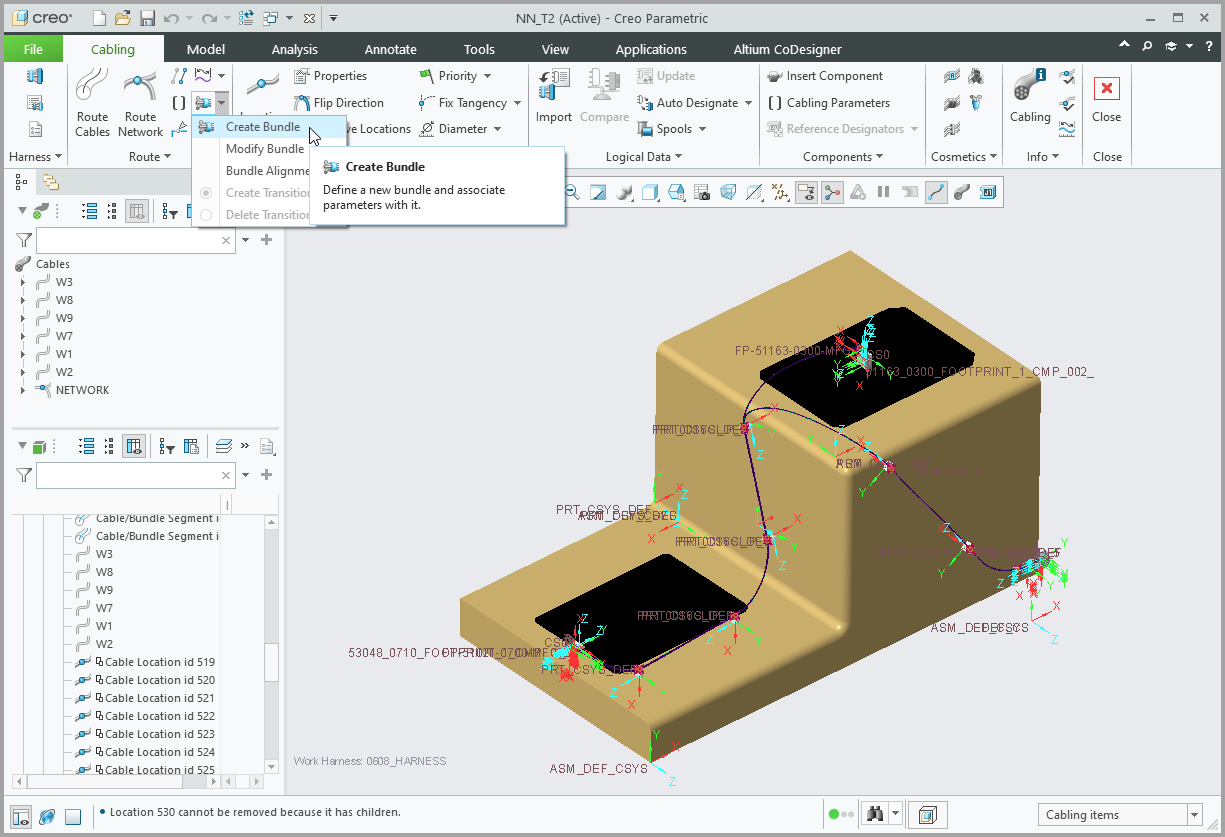
The next (optional) step is to create bundles for these wires, making it easier to work with the harness in Creo.
-
Create the first bundle:Expand折りたたむ
- Create and name the bundle (eg B1), using the Create Bundle button on the Cabling ribbon.
- Set the Grouping menu manager to Round.
- For the Spool Name, click Create and name the Spool (eg, BS1)
- The Electrical Parameters dialog will open, select the Spool, then set the Wall Thickness as required (eg 0.1), and the Minimum Bend Radius (eg 0.06)
- When the dialog is closed, the Bundle Options menu manager will appear, select Along Path.
- As detailed on the Status bar, you now click to choose a starting point for the bundle, then an endpoint.
- After selecting the endpoint, the menu manager will prompt you to select which wires to include, click Select All, then Done Sel.
- Since you will not be reading Bundle parameters from a file, click the OK button to leave the parameters as they are, then click the Done button in the menu manager.
- Repeat the process for the second bundle segment, naming it BS2.
-
To display the Physical view of the Bundle, click the Thick Cables button on the toolbar.
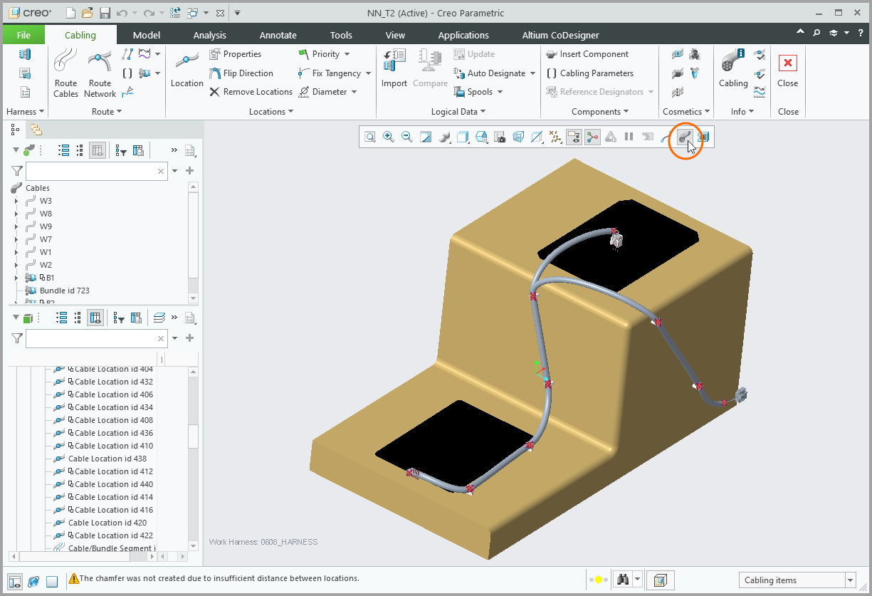
- The Harness has been defined in PTC Creo, and is now ready to Push back to ECAD.
From Creo, Open the Harness Project in your Web Browser
From Creo, you can also open the harness project stored in your Altium Workspace directly in your web browser. Here you can examine all of the ECAD project files, including the Harness drawing, the Layout drawing, the BOM and the Draftsman drawing (if they have been created).
 Open and examine any of the ECAD Harness project files in your web browser.
SOLIDWORKS - Shape the Harness in the Device Assembly
CoDesigner works with SOLIDWORKS Routing Electrical capabilities. To shape the harness in SOLIDWORKS:
From SOLIDWORKS, Open the Harness Project in your Web Browser
From SOLIDWORKS, you can also open the harness project stored in your Altium Workspace directly in your web browser. Here you can examine all of the ECAD project files, including the Harness drawing, the Layout drawing, the BOM and the Draftsman drawing (if they have been created).
 Open and examine any of the ECAD Harness project files in your web browser.
MCAD - Push the Harness and Multi-board Assembly to ECAD
- Open the Altium CoDesigner panel. If you are working in the context of the device assembly, the dropdown at the top of panel will list all of the projects that CoDesigner recognizes, select the Harness from the list to make it the active project. You can also synchronize the Harness if the assembly has been opened on its own.
- Click Push, include a suitable Comment, and click Send to Push the Harness definition to the Workspace.
-
The last step is to Push the entire device assembly to ECAD:Expand折りたたむ
- In the Altium CoDesigner panel, select the device assembly from the active project dropdown.
- To include all of the mechanical parts into the enclosure, in the model tree multi-select: the enclosure, the Harness, and all of the clips. You do not need to include the PCBs.
- On the Altium CoDesigner ribbon, click the Enclosure button (show image
![]() ).
).
- A confirmation dialog will indicate that this has been successful, and all of the mechanical items will be listed in the panel. If it is not successful, the most likely cause is that the device assembly was not made the active project.
- CoDesigner does not build or change the Harness Topology in ECAD's Layout Drawing after synchronizing back from MCAD, so the Harness Topology should be specified in that document before back synchronization.
- In MCAD, the Wire Lengths are calculated automatically, and sent back to ECAD during a Push. The calculated values can be adjusted in MCAD if required, by defining a Corrected Length value in the Length of Harness Objects section of the Altium CoDesigner panel in MCAD. Note that the units displayed in the panel are the current model units. If you change the units, click the Reload Data button (
 ) in the panel to refresh the Calculated and Corrected Length values. In ECAD, wire lengths can be displayed in the Draftsman document, and the ActiveBOM document. The ability to adjust the wire length was added in CoDesigner 3.8.
 Auto-calculated wire lengths can be adjusted, if required.
ECAD - Pull the Harness and Multi-board Assembly to ECAD
- Each Harness assembly must be synchronized with its ECAD Harness project.
- If you are synchronizing the MCAD device assembly with the ECAD Multi-board assembly, you must also: synchronize each PCB project from MCAD to ECAD; and update each PCB in the Multi-board Assembly (if they have already been inserted).
- Performing a Pull in an ECAD Harness project will load the physical lengths of wires, cables, and harness segments into the Harness Layout Drawing.
- Performing a Pull in an ECAD Multi-board assembly will: pull and apply location and orientation changes for each PCB; load and position all 3D models (in STEP format) that are part of the enclosure; and load and position the Harness as a STEP model.
-
Open the Multi-board assembly in ECAD, then in the MCAD CoDesigner panel, Pull the assembly from the Workspace.
 The Multi-board assembly, complete with boards, harness, and enclosure, can be synchronized between MCAD and ECAD.
Harness Changes that can be transferred from ECAD to MCAD
- The set of wires and cables.
- Connectivity information (from-to data).
- Topology (connection points with the sets of wires and cables going through those points).
Harness Changes that can be transferred from MCAD to ECAD
- To the Harness Layout Drawing (
*.LdrDoc) - The physical length of wires, cables, and harness segments.
- To the Multi-board Assembly (
*.PrjMbd) - The 3D model of the Harness can also be sent to ECAD during Multiboard Assembly synchronization, along with the mechanical enclosure parts.
