PCB設計に対して準備および生成できるアセンブリファイル形式には、以下が含まれます:
-
アセンブリ図面
-
ピックアンドプレースファイル
-
アセンブリテストポイントレポート
-
ワイヤーボンディングテーブルレポート
アセンブリ出力は、[Add New Assembly Output]コントロールのメニューから、またはファイルのAssembly Outputs領域やメインメニューのEdit » Add Assembly Outputsサブメニューから、アクティブな出力ジョブファイルに追加できます。

OutputJobファイルは、設計の出力の準備とその後の高信頼性プロジェクトリリースプロセスを使用した生成を効率化しますが、アクティブなPCB設計のアセンブリ出力は、File » Assembly Outputsサブメニューのコマンドを使用してPCBエディターから直接生成することもできます。
アセンブリ図面の準備
Assembly Drawings 出力は、ページとその上のレイヤーに対して事前に定義された設定を持つ印刷ベースの出力です。Printダイアログにアクセスして、出力の設定を確認および調整します。
PCBプリントアウトの設定ページを参照して、詳細を学びましょう。
ピックアンドプレースファイルの準備
Generates pick and place出力ジェネレータは、ボード上の各コンポーネントの位置、回転、およびボードの面を詳細に記述したレポートを生成します。レポートはCSVまたはテキスト形式で生成できます。Standardとされているコンポーネントタイプのすべてのコンポーネントがレポートに含まれます。Graphicalなど、他の値に設定されているコンポーネントタイプのコンポーネントは含まれません。
必要なレポートは、Pick and Place Setupダイアログで設定されます。

Pick and Place Setupダイアログ
Pick and Place Setupダイアログのオプションとコントロール
-
All Columns - 出力ファイルに含めることができるパラメータのリストから選択します。表示したいパラメータの列を有効にします。位置情報は、ソースPCBライブラリでコンポーネントフットプリントの基準点が指定される3つの方法に対応して3通りの方法で表現されます:
-
Center X、 Center Y - コンポーネントの中心点の座標(最も外側のパッド位置の中間点として計算されます)
-
Ref X、 Ref Y - コンポーネントのユーザー定義の基準点(フットプリントの原点)の座標
-
Pad X、 Pad Y - コンポーネントのパッド1の座標。
-
グリッド領域 - この領域は、出力ファイルに含まれる情報のプレビューです。
-
Output Settings
-
Units- この領域を使用して、コンポーネントの位置座標の測定単位としてImperialまたはMetricのどちらを使用するかを指定します。
-
Show Units - 単位を表示するように有効にします。
-
Separator- ドロップダウンから望ましい単位区切り文字を選択します。
-
Formats - 出力を生成する形式(CSVおよび/またはテキスト)を選択します。
-
Exclude Filter Parameters - フィルタリングに使用されているパラメータを除外するように有効にします(詳細については、以下のTipsセクションを参照してください)。
-
Include Variation Component - バリアントを含めるように有効にします。
-
Distinguish different footprints with the same name - 有効にすると、同じ名前を持つフットプリントのうち1つが変更された場合、変更されたフットプリントのみが出力で変更されます。このオプションが有効でない場合、同じ名前を持つすべてのフットプリントが出力で変更されたと表示されます。
-
Include Standard (No BOM) Items - フィデューシャルをサポートするために標準コンポーネントを含めるように有効にします。
-
Y-Flip Bottom Side Components - ボトムレイヤーのコンポーネントのRef-YおよびPad-Y値の符号を反転させるオプションを有効にします。
フィルタリング
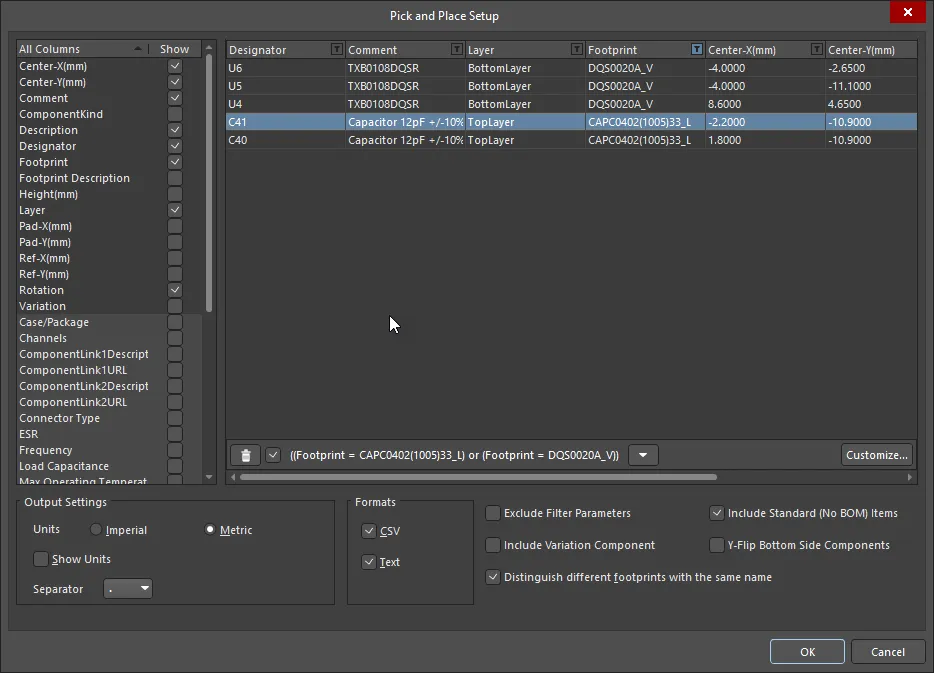
フィルタリングが適用された場合、ピックアンドプレース設定ダイアログは上記のように表示されます。このバリエーションには、追加のコントロールが含まれます:
-
 - 右側に表示されているフィルタリングを削除するためにクリックします。フィルタリングを完全に削除するのではなく、右側のチェックボックスを使用してフィルタリングを有効/無効にします。
-
下矢印 - 以前のフィルタリングのリストにアクセスするためにクリックします。現在のグリッドをフィルタリングするために望ましいフィルタリングを選択します。
-
Customize- より高度で複雑なフィルターを作成するためのFilter builderダイアログを開くためにクリックします。
特定の部品をレポートから除外するために、ダイアログではカスタムフィルタリングを適用する機能を提供します。フィルタリングを適用するには、列ヘッダーのフィルターアイコン(  )をクリックします。その後のメニューでは、すべての個々の行エントリがクイック選択フィルタリングのためにリストされています。
(Custom…)エントリをクリックして、 カスタムフィルターダイアログにアクセスします。その列に定義されたフィルタリング基準に基づいてBOMに表示するデータ行を指定するためにダイアログを使用します。適用されると、フィルターアイコンは青色(  )に変わり、その列にカスタムフィルタリングが適用されていることを示します。必要に応じて他のデータ列にカスタムフィルタリングを適用します - 現在適用されているフルフィルターは、データ領域の左下に反映されます。フィルタリングに使用されている列も、Exclude Filter Parametersオプションを有効にすることで、生成されたピックアンドプレースファイルから除外することができます。
アセンブリテストポイントレポートの準備
アセンブリテストポイントレポートジェネレータは、アセンブリテストポイントとして使用されるすべてのパッドとビアのレポート(txtおよび/またはcsvおよび/またはIPC-D-356A形式)を生成します。
ボード上のテストポイントの割り当てページを参照して、PCB設計でテストポイントを割り当てる方法について詳しく学びましょう。
テストポイントレポートは、組み込みボードアレイをサポートしています。複数の組み込みボードアレイを含むPCBドキュメントからエクスポートされた場合、複数のIPC-D-356Aネットリストファイルが生成されます。
アセンブリテストポイントレポートの出力オプションは、Assembly Testpoint Setupダイアログを使用して設定されます。

Assembly Testpoint Setupダイアログ
