プリント基板の配線は詳細で反復的なプロセスです。全てのネットを一度に単純に配線できることは稀です。より一般的には、一連のネットを配線し、次の一連のネットに移るにつれて、既存の配線を継続的に調整し、移動させることになります。これは、手動でドラッグする場合もあれば、インタラクティブにさらに多くのネットを配線する際に押したり、押しのけたりする場合もあります。 その結果、完成した配線はオート配線されたように見えることがあり、不必要なジグやコーナーが多くなります。
既存の配線の再配線と再配置
ボードの配線は、コンポーネントの位置決めと配線の完了に取り組むにつれて、複雑で時間がかかるプロセスになります - そのコンポーネントをわずかに移動させ、その配線を押しのけ、潜在的なクロストークを避けるためにそれらの重要なネットを再配線し、そのエリアを通してそのバスを配線できるかどうかを確認し、といった具合です。ボードを配線する際には、既に行った配線を常に変更していきます。 配線を変更するには2つのアプローチがあります。再配線するか、再配置するかです。
再配線は、新しい配線パスが単にいくつかのトラックセグメントを移動するよりも複雑な場合に理想的です。再配線は、インタラクティブ配線(またはインタラクティブ差動ペア配線)コマンドを使用して、初期配線と同じ方法で実行されます。新しい配線パスを完了すると、冗長なトラックセグメントの古いループが削除されます。
代わりに、配線を再配置することができます。既存の配線を再配置するには、トラックセグメントをクリックして保持し、新しい位置にドラッグします。接続されたトラックセグメントは、以前接続されていた角度で接続されたままになります - これはインタラクティブスライディングと呼ばれる動作です(元の配線で定義された直交/対角パターンを維持するため)。インタラクティブスライディングは、インタラクティブ配線中に利用可能な同じセットの配線技術を呼び出すことができ、衝突解決モードをサポートしています。これには、プッシュ、ハグアンドプッシュ、無視が含まれます。
移動 - それに接続されている他のオブジェクトに関係なくオブジェクトを移動します。
ドラッグ - オブジェクトを移動し、接続されているオブジェクトがそれに接続されたままになるようにします。接続されたオブジェクトは、元の配置角度を保持する場合も保持しない場合もあります。
スライド - 配線オブジェクトを移動し、接続されたオブジェクトが接続されたままになり、それらのオブジェクトが元の配置角度を保持します。
既存のルートの再配線
-
そのパスを再定義するために接続をアンルートする必要はありません。単にInteractive Routingボタンをアクティブバー( 
 )でクリックし、新しいパスの配線を開始します。
-
ループ削除機能は、ループを閉じて右クリックして完了を示すとすぐに、冗長なトラックセグメント(およびビア)を自動的に削除します。
-
新しいルートパスは、必要に応じてレイヤーを切り替えながら、任意の点で開始および終了できます。
-
障害物無視モードに切り替えることで一時的な違反を作成することもできます(下のビデオで示されています)。これは後で解決します。
既存の配線を変更するためにループ削除機能が使用されている簡単なアニメーション。
ループ削除機能は、PreferencesダイアログのPCB Editor – Interactive Routingページで有効になっています。電源ネットの配線など、ループを作成したい場合があることに注意してください。必要に応じて、ループ削除を個々のネットに対して無効にすることができます。そのオプションにアクセスするには、PCBパネルをNetsモードに設定し、パネル内のネット名をダブルクリックしてEdit Netダイアログを開きます。
ループ削除中に、既存の配線に戻るが新しいパスの定義をまだ終えていない状況があります。Automatically Terminate Routingオプションが有効になっていると、新しいルートが既存のルートと重なるとすぐに、配線プロセスが終了し、古い冗長な配線が削除されます。この状況では、Automatically Terminate Routingオプションを無効にする方が効率的な場合があります。
既存のルートの再配置
-
ボード上でトラックセグメントを対話的にスライドまたはドラッグするには、下記のビデオに示されているようにクリックしてホールドし、ドラッグしてください。
-
デフォルトのドラッグ動作は、PreferencesダイアログのPCB Editor - Interactive Routingページで設定されています。
-
PCBエディタは、接続されたセグメントに対して自動的に45度と90度の角度を維持し、必要に応じてそれらを短くしたり長くしたりします。
スライドオプションをボードで使用した配線スタイルに合わせて設定することが重要です。たとえば、対角線のコーナーで配線した場合、ハギングスタイルは45 DegreeまたはMixedに設定する必要があります。Roundedに設定されている場合、グロッシングエンジンはスライディングアクションの影響を受ける各コーナーを曲げ(アークを追加)します。
既存の配線を変更するために使用されるインタラクティブスライディングのデモンストレーション。
インタラクティブスライディングのヒント:
-
スライド中にTabキーを押すと、スライド設定を変更できるPropertiesパネルにアクセスできます。
-
インタラクティブスライドオプションをボードで使用される配線スタイルに合わせて設定します。たとえば、配線に対角コーナーがある場合、Hugging Styleは45 Degreeにする必要があります。スライド中にHugging Styleモードを切り替えるには、Shift+Spacebarのショートカットキーを押してください。
-
スライド中は、Routing Conflict Resolutionモードの一つ(無視、押す、抱きしめて押す)が適用されます。トラックセグメントをドラッグしながら、Shift+Rを押してモードを切り替えます。

配線競合モードをプッシュに設定して、複数のトラックをドラッグする例
-
90度のコーナーを45度のルートに変換するには、コーナーの頂点をドラッグし始めます。
-
インタラクティブスライディングエンジンには、頂点(コーナー)をドラッグするためのアルゴリズムが含まれています。PreferencesダイアログのVertex Actionや、PropertiesパネルのInteractive Slidingモードで構成します。頂点をドラッグしながらSpacebarを押すことで、モードを切り替えます
-
頂点(トラックの端が交差する点)をクリックしてドラッグすると、現在のVertex Action設定が適用されます。コーナーの形を変えたい場合は、Deformモードを使用してください。
-
1つのセグメントを分割するには、まずそのセグメントを選択し、次にカーソルを中央の頂点に合わせて新しいセグメントを追加します。
-
Allow Via Pushingオプションが有効な場合、既存のパッドとヴィアはジャンプされるか、必要かつ可能な場合はヴィアがプッシュされます。
-
インタラクティブスライディングは、非直交配線をサポートしています。
-
移動するトラックがスライドする際にどの程度再形成されるかは、現在のGloss Effort (Routed)設定によって制御されます。スライド中にモードをサイクルするには、Ctrl+Shift+Gのショートカットを押してください。配線が思い通りにスライドしない場合は、Routing Gloss Effort設定を下げてみてください。
-
移動するトラックが隣接する配線に与える影響は、現在のGloss Effort (Neighbor)設定によって制御されており、スライド中に設定を変更するにはTabキーを押します。
-
デフォルトの動作は、トラック(選択されたものまたは選択されていないもの)をドラッグ(スライド)することです。接続されたセグメントとの接続を維持せずにセグメントを移動する必要がある場合は、PreferencesダイアログのPCB Editor - Interactive RoutingページにあるUnselected via/trackまたはSelected via/trackオプションを使用して、デフォルトのドラッグ動作を変更してください。
-
スライドしている配線は、現在のスナップグリッドにスナップするだけでなく、カーソルのスナップ動作は、オブジェクトのスナップ設定とレイヤースナッピング設定の組み合わせに依存し、スナップガイドと軸スナッピング設定が有効になっている場合(これらをオン/オフに切り替えるにはCtrl+Eを押してください)にも依存します。インタラクティブなスライディング中にスナップを一時的に抑制するには、Ctrlキーを押し続けてください。カーソルスナップシステムの操作について詳しく学びましょう。
-
ルートをスライドさせる際に、カーソルを移動させ、ホットスポットを動画の下に示されたようにパッドなどの既存の非移動オブジェクトにスナップできます。これにより、新しいセグメントの位置が既存のオブジェクトと整列し、非常に小さいセグメントを追加するのを避けることができます。
既存の配線を変更するためにトラックドラッグが使われている様子を示すビデオ。
-
現在の配線を構成するオブジェクトをより簡単に見るために、View Configurationパネルで配線オブジェクトのTransparencyを調整します。(画像を表示)
► パネルで利用可能なインタラクティブスライディングおよびインタラクティブ配線オプションのセクションで説明されています。
インタラクティブスライディングオプション
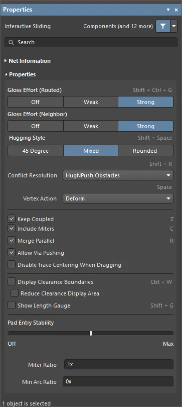
スライディングプロセスの可視性と制御を向上させるために、PropertiesパネルにはInteractive Slidingモードが含まれています - スライディング中にTabを押すと、パネルのオプションにアクセスできます。デフォルト設定は、PreferencesダイアログのPCB Editor - Interactive Routingページで構成されています。

以下の折りたたみ可能なセクションには、利用可能なインタラクティブスライディングオプションとコントロールに関する情報が含まれています:
ネット情報

-
Net – ドラッグされているネットの名前とネットクラス(またはクラス)を表示します。
-
Diff Pair – ドラッグされているネットが差動ペアの一部である場合、このフィールドはその差動ペアの名前と差動ペアクラス(またはクラス)を表示します。
-
Length – 総信号長です。信号長は、ノード間の総距離の正確な計算です。配置されたオブジェクトは、重なっているか重複しているオブジェクトとパッド内の迷走パスを解析し、ビアの長さも含まれます。
-
Delay – 選択されたセグメントの総遅延を含み、未配線のものも含みます。
プロパティパネルのNet、Diff Pair、Length、およびDelayのクリック可能なリンクを選択して、PCBパネル のネットまたは差動ペアエディタモードにリダイレクトされ、関連するネット/差動ペアの詳細を表示および変更できます。
プロパティ
-
Gloss Effort (Routed) – パネルから望ましいグロスレベルを選択するか、Shift+Ctrl+Gショートカットを使用して次の選択肢をサイクルします:
-
Off – このモードでは、基本的にグロッシングは無効になります。ただし、配線/ドラッグ後にクリーンアップが実行されて重複するトラックセグメントを排除することに注意してください。このモードは、ボードレイアウトの最終段階で最終的な微調整が必要な場合(例えば、トラックを手動でドラッグしたり、パッドエントリをクリーニングしたりする場合など)に通常役立ちます。
-
Weak – このモードでは、低レベルのグロッシングが適用され、インタラクティブルーターは現在配線している(またはドラッグしている)トラックやビアに直接接続されている、またはそのエリアのトラックのみを考慮します。このグロッシングモードは、トラックレイアウトの微調整や、重要なトレースを扱う場合に通常役立ちます。
-
Strong – このモードでは、高レベルのグロッシングが適用され、インタラクティブルーターは最短パスを探し、トラックを滑らかにするなどします。このグロッシングモードは、レイアウトプロセスの初期段階で、迅速にボードの大部分を配線することを目指す場合に通常役立ちます。
-
Gloss Effort (Neighbor) – 現在配線しているネットによって押し出されるトレースに適用する望ましいグロスレベルをパネルから直接選択します:
-
Off – このモードでは、基本的にグロッシングは無効になります。ただし、配線/ドラッグ後にクリーンアップが実行されて重複するトラックセグメントを排除することに注意してください。このモードは、ボードレイアウトの最終段階で最終的な微調整が必要な場合(例えば、トラックを手動でドラッグしたり、パッドエントリをクリーニングしたりする場合など)に通常役立ちます。
-
Weak – このモードでは、低レベルのグロッシングが適用され、インタラクティブルーターは現在配線している(またはドラッグしている)トラックやビアに直接接続されている、またはそのエリアのトラックのみを考慮します。このグロッシングモードは、トラックレイアウトの微調整や、重要なトレースを扱う場合に通常役立ちます。
-
Strong – このモードでは、高レベルのグロッシングが適用され、インタラクティブルーターは最短パスを探し、トラックを滑らかにするなどします。このグロッシングモードは、レイアウトプロセスの初期段階で、迅速にボードの大部分を配線することを目指す場合に通常役立ちます。
-
Hugging Style – コーナーの形状がインタラクティブなスライド中にどのように管理されるかを制御し、スライドされるトラックと押されるトラックの両方に影響を与えます。スライド中は、Shift+Spacebarショートカットを使用して三つのモードを切り替えます。
-
45 Degree – スライディング中は常に直線の直交または対角セグメントを使用してコーナーを作成します(従来の直交/対角配線動作にはこのモードを使用してください)。
-
Mixed – 移動させる対象物が直線の場合は直線トラックセグメントを使用し、曲がっている場合はアークを使用します。
-
Rounded – 移動/押しに関与する各頂点でアークを使用します。このモードは、スネーク配線や、インタラクティブ配線および手動グロッシング中にアークと任意の角度のルートを使用するために使用してください。
-
Conflict Resolution – 既存のオブジェクトと遭遇したときにスライドするオブジェクトがどのように反応するかを決定します。ドロップダウンを使用するか、Shift+Rショートカットを使用して目的の配線モードを循環させます。以下の選択肢が利用可能です:
-
Ignore Obstacles – 既存のオブジェクトを無視するように選択します(配線は自由に配置できます)。違反は強調表示されます。
-
Walkaround Obstacles – インタラクティブルーターに既存のトラック、パッド、ビアを回避して配線するよう選択します。このモードが障害物を違反なく回り込めない場合、ルートがブロックされていることを示すインジケーターが表示されます。
-
Push Obstacles – インタラクティブルーターに既存のトラックを移動させるよう選択します。このモードは、新しい配線のためにビアを押し出すこともできます。このモードが障害物を押し出すことによって違反を引き起こすことなく実行できない場合、ルートがブロックされていることを示すインジケーターが表示されます。
-
HugNPush Obstacles – インタラクティブルーターが既存のトラック、パッド、ビアにできるだけ近く、必要に応じて障害物を押しのけてルートを続行するように選択します。このモードが違反を引き起こすことなく障害物に寄り添ったり押したりできない場合、ルートがブロックされていることを示すインジケーターが表示されます。
-
Stop At First Obstacle – このモードでは、配線エンジンは道を阻む最初の障害物で停止します。
-
AutoRoute Current Layer – 現在のレイヤーでのみ自動配線を有効にするを選択します。
-
AutoRoute MultiLayer – 複数のレイヤーで自動配線を有効にするには選択してください。
-
Vertex Action – トラックや弧ではなく、頂点をクリックしてドラッグしたときに適用されるオプション(頂点は2つのセグメントが交わる角の位置です)。スライディング中に使用可能なモードを切り替えるには、Spacebarショートカットを使用してください。
-
Deform – 動いている頂点に付随するトラックセグメントを断ち切るか長くして、頂点がカーソルの動きに従うようにします。(アニメーションを表示)
-
Scale – コーナーの形を保持し、頂点をカーソルに付けたまま、受信トラックセグメントをサイズ変更および移動します。(アニメーションを表示)
-
Smooth – コーナーを滑らかに再形成し、内側にドラッグするときにアークを挿入して曲線コーナーを作成します(ミックスまたはラウンドハギングスタイルで)、スライドプロセスに影響を受けるすべての頂点で。さらに、ラウンドハギングスタイルで外側にドラッグするときにもアークを追加します。
-
Keep Coupled – このオプションをチェックして、差動ペアに属するオブジェクトがペアのパートナートラックまたはバイアスにドラッグされることを確認してください。
-
Include Miters – トラックセグメントをドラッグする際にマイターを含めるには、このオプションをチェックしてください。
-
Merge Parallel – このオプションをチェックすると、ドラッグされたトラックセグメントが既存の静止セグメントと整列した際にマージされることを許可します。
-
Allow Via Pushing – プッシュ障害物またはハグ&プッシュ障害物モードのときに、Viaをプッシュできるようにするには、このオプションをチェックしてください。
-
Disable Trace Centering When Dragging – オプションが有効になっている場合、インタラクティブスライディング中にトレースセンタリングは適用されません(たとえ、PreferencesダイアログのPCB Editor – Interactive RoutingページでApply Trace Centeringオプションが有効になっていても)。
-
Display Clearance Boundaries – 既存のオブジェクトと適用されるクリアランスルールによって定義されたノーゴークリアランスエリアを、ローカルビュイングサークル内にシェーディングポリゴンとして表示できるようにします。このオプションは、Ignore Obstacles配線モードでは利用できません。
-
Show Length Gauge – 現在の配線された長さを表示する長さゲージを表示可能にします。ゲージの設定は、適用される設計ルールによって定義された制約のセットから計算されます。配線中に表示をオンまたはオフに切り替えるには、Shift+Gショートカットを使用してください。
-
Pad Entry Stability – 中央パッドエントリーを保護します。スライダーを使用して保護レベルを設定します:
-
Miter Ratio - 最小のコーナーの締まりを制御します。マイター比に現在のトラック幅を乗じたものが、その比率で配線できる最も締まったU字形の壁間の隔たりになります。ゼロ以上の正の値を入力してください(xの乗数は自動的に追加されます)。インタラクティブ配線ページを参照して、マイター角について詳しく学びましょう。
-
Min Arc Ratio - 任意の角度のインタラクティブ配線およびMixedハギングスタイルでのインタラクティブスライディング中に適用されます。この比率は、許可される最小半径のアークを決定するために使用され、アーク半径がこの最小値を下回ると、アークはトラックセグメントに置き換えられます。ここで、Min Arc Radius = Min Arc Ratio x Arc Widthです。
常にアークを使用するには、最小アーク比を0(ゼロ)に設定します。
T字路の修正
T字路をインタラクティブに修正するための特定のアルゴリズムが含まれています - T字路の接合点をクリックしてドラッグすると、T字路を修正できます。
T字路のドラッグ機能の例。
インタラクティブビアドラッグ
PCB設計者は、遅れた設計変更のためや、設計を完成させるために、配線の調整に多くの時間を費やすことがあります。これには、既存の配線を押したり引いたり、ビアをドラッグしたり、コンポーネントを微調整したりすることが含まれます。
 Propertiesパネルでビアドラッグの動作を調整します。
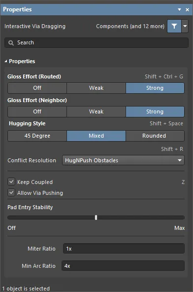
隣接ルートのグロッシングサポートを補完するため、ビアドラッグもサポートされています。ビアドラッグは、PCBエディタのInteractive Via DraggingモードのPropertiesパネルを通じて設定されるNeighbor Glossingをサポートします。ビアをドラッグ中にTabを押してパネルにアクセスし、設定を調整します。
ビアをドラッグするときにTabを押してビアドラッグオプションを設定します。
以下の折りたたみセクションには、利用可能なインタラクティブビアドラッグオプションとコントロールに関する情報が含まれています:
プロパティ
-
Gloss Effort (Routed) - パネルからドラッグされているビアに接続されているトレースの望ましいグロスレベルを選択するか、Shift+Ctrl+Gショートカットを使用して次の選択肢をサイクルします:
-
Off - このモードでは、基本的にグロッシングは無効になります。ただし、ドラッグ後にはクリーンアップが実行され、例えば、重なっているトラックセグメントを排除します。このモードは、ボードレイアウトの最終段階で最終的な微調整が必要な場合に通常有用です。
-
Weak - このモードでは、ドラッグされているビアに直接接続されているトラックのみを考慮して低レベルのグロッシングが適用されます。このグロッシングモードは、トラックレイアウトの微調整や、クリティカルなトレースを扱う場合に通常有用です。
-
Strong - このモードでは、最短経路を探す、トラックを滑らかにするなど、高レベルのグロッシングが適用されます。このグロッシングモードは、レイアウトプロセスの初期段階で、迅速にボードの大部分を配線することを目指す場合に通常有用です。
-
Gloss Effort (Neighbor) - 現在ドラッグされているビアによって押されているトレースに適用する望ましいグロスレベルをパネルから直接選択します。次の選択肢があります:
-
Off - このモードでは、基本的にグロッシングは無効になります。ただし、ドラッグ後にはクリーンアップが実行され、例えば、重なっているトラックセグメントを排除します。このモードは、ボードレイアウトの最終段階で最終的な微調整が必要な場合に通常有用です。
-
Weak - このモードでは、ドラッグされているビアに直接接続されているトラックのみを考慮して低レベルのグロッシングが適用されます。このグロッシングモードは、トラックレイアウトの微調整や、クリティカルなトレースを扱う場合に通常有用です。
-
Strong - このモードでは、最短経路を探す、トラックを滑らかにするなど、高レベルのグロッシングが適用されます。このグロッシングモードは、レイアウトプロセスの初期段階で、迅速にボードの大部分を配線することを目指す場合に通常有用です。
-
Hugging Style - インタラクティブなドラッグ中にコーナー形状がどのように管理されるかを制御し、ドラッグされているビアに接続されたトラックと押されているトラックの両方に影響を与えます。ビアをドラッグする際は、Shift+Spacebarのショートカットを使用して三つのモードを循環させます。
-
45 Degree – ドラッグ中は常に直線的な直交/対角セグメントを使用してコーナーを作成してください(従来の直交/対角配線動作にはこのモードを使用します)。
-
Mixed – 移動させる対象物が直線の場合は直線トラックセグメントを使用し、曲がっている場合はアークを使用します。
-
Rounded – 移動/押しに関与する各頂点でアークを使用します。
-
Conflict Resolution – ドラッグされたオブジェクトが既存のオブジェクトと遭遇したときの反応をどのように設定するかを決定します。ドロップダウンを使用するか、Shift+Rショートカットを使用して希望するモードをサイクルします。次の選択肢があります:
-
Ignore Obstacles – 既存のオブジェクトを無視するように選択します(配線は自由に移動可能です)。ドラッグ後に違反が強調表示されます。
-
Walkaround Obstacles – 既存のトラック、パッド、ビアの周りにトラックを配置するように配線エンジンを選択します。
-
Push Obstacles – 配線エンジンが可能な範囲で既存の配線を避けるように選択します。このモードではビアも押し出すことができます。
-
HugNPush Obstacles – 配線エンジンに既存のトラック、パッド、ビアにできるだけ密着させ、必要に応じて障害物を押しやってルートを維持するよう選択します。
-
Stop At First Obstacle – このモードでは、配線エンジンは道を阻む最初の障害物で停止します。
-
Keep Coupled – このオプションを有効にすると、差動ペアに属するビアをドラッグする際に、パートナーをドラッグしようとすることができます。
-
Allow Via Pushing – このオプションを有効にすると、Push ObstaclesまたはHugNPush Obstacles衝突解決モードの際にビアをプッシュできるようになります。
-
Pad Entry Stability – 中央パッドエントリーを保護します。スライダーを使用して保護レベルを設定します:
-
Miter Ratio – コーナーの最小のきつさを制御します。ミターレシオに現在のトラック幅を掛けると、その比率に対して経路を作成できる最もきついU字型の壁の間隔になります。ゼロ以上の正の値を入力してください(x乗数は自動的に追加されます)。ミタードコーナーについての詳細は、インタラクティブ配線ページを参照してください。
-
Min Arc Ratio – Mixedハグスタイルでドラッグによるインタラクティブアプリケーションが適用されました。この比率は、アーク半径がこの最小値を下回るときに許可される最小半径アークを決定するために使用されます。Min Arc Radius = Min Arc Ratio x Arc Widthです。
差動ペアドラッグ
差動ペアのメンバーを認識するために、カップリングの概念が使用されます。ソフトウェアが差動ペアに属するオブジェクトを認識すると、PropertiesパネルのInteractive SlidingまたはInteractive Via DraggingモードでKeep Coupledオプションが有効になっている場合、ペアのパートナートラックやビアをドラッグしようとします。
Xを押しながら、経由ペアをドラッグしてペアを90度回転させます。
パートナーオブジェクトが結合されていることを確認するために、ソフトウェアはオブジェクトが次のことをチェックします:
配線、再配線、インタラクティブスライディングに影響を与えるオプション
いくつかのオプションが配線の挙動に影響を与えます。これらのオプションは、PreferencesダイアログのPCB Editor - Interactive Routingページで構成されます。

-
Automatically Remove Loopsオプションは、再配線を実行するために有効にする必要があります。電源ネットの配線など、ループを作成したい場合があります。必要に応じて、PCBパネルでそのネットを編集することにより、個々のネットに対してループ削除を無効にすることができます。このオプションにアクセスするには、パネルをNetsモードに設定し、パネル内のネット名をダブルクリックしてEdit Netダイアログを開きます。
-
インタラクティブ配線と同様に、現在のRouting Conflict Resolutionモードが使用されます。
-
Automatically Terminate Routingオプションは便利です。これが有効になっていると、新しいルートが既存の配線に接続するとすぐに、冗長なループが削除されます(上のビデオで示されているように)。このオプションが無効になっている場合、現在のルートを解放するために右クリックしたときにループが削除されます。既存の配線の上に新しい配線を配置する必要がある場合(おそらく重なる場合)、このオプションは逆効果になる可能性があるため、その状況では無効にする方が良いかもしれません。
-
Glossing Effortオプションは、配線エンジンが修正されている配線をどの程度滑らかにまたはグロスするかを制御し、これは Hugging Style、Arc Ratio、Miter Ratio、およびPad Entry Stabilityの設定に基づいて行われます。グロッシングについての詳細は、配線の品質を向上させるセクションで学ぶことができます。
インタラクティブ配線とインタラクティブスライディングオプション
接続をインタラクティブに配線するか、既存のルートをドラッグしてより多くの配線のためのスペースを作るかにかかわらず、同じセットの配線技術が適用されます。このセクションでは、PropertiesパネルのInteractive RoutingおよびInteractive Slidingモードで利用可能なオプションを要約します。作業中にTabを押して、関連するモードでPropertiesパネルを開きます。設定を変更した後、画面の中央にある アイコンをクリックして、配線またはスライディングに戻ります。これらのオプションのデフォルト設定は、PreferencesダイアログのPCB Editor - Interactive Routingページで構成されています。
インタラクティブ配線とインタラクティブスライディングオプション
配線グロス効果(ルーテッド)
配線イベント、例えばインタラクティブ配線、インタラクティブスライディング、またはActiveRouting中に、ソフトウェアはグロッシングエンジンを実行します。グロッシングエンジンは、現在のルートイベントによって配置されたまたは影響を受けたすべてのセグメントを常にレビューし、結果の品質を向上させようとします。品質の尺度には、コーナーとセグメントの数を減らす、鋭角を取り除く、および全体的なルートの長さを短縮することが含まれます。
グロッシングには3つの設定があります:
-
Off - このモードでは、グロッシングは基本的に無効になります。ただし、配線/ドラッグ後にクリーンアップが実行されて、たとえば重なっているトラックセグメントを排除することに注意してください。このモードは、ボードレイアウトの最終段階で最終的な微調整が必要な場合(たとえば、トラックを手動でドラッグして、パッドエントリをクリーニングするなど)に役立ちます。
-
Weak - このモードでは、低レベルのグロッシングが適用され、インタラクティブルーターは現在配線しているトラック(またはドラッグされているトラック/ビア)に直接接続されているトラックのみを考慮します。このグロッシングモードは、トラックレイアウトを微調整する場合や、クリティカルなルートを扱う場合に通常役立ちます。
-
Strong - このモードでは、高レベルのグロッシングが適用され、インタラクティブルーターは最短経路を探し、トラックを滑らかにするなどを行います。このグロッシングモードは、レイアウトプロセスの初期段階で、迅速に良い量のボードを配線することを目指す 最小アーク比を0(ゼロ)に設定して、常にアークを使用します。
配線グロス効果(隣接)
グロス効果(隣接)は、現在のインタラクティブ配線またはスライディングによって影響を受ける隣接ルートに適用されるグロスの量を構成します。また、オフ、弱い、強いの3つの設定があります。
ハギングスタイル
このオプションは、インタラクティブなスライディング中にコーナーの形状がどのように管理されるかを制御し、スライドしているトラックと押されているトラックの両方に影響を与えます。スライディング中は、Shift+Spacebarショートカットを使用して3つのモードを循環します。
-
45 Degree - スライディング中は常に直線の直交または対角セグメントを使用してコーナーを作成します(従来の直交/対角配線動作にはこのモードを使用してください)。
-
Mixed - 移動させる対象物が直線の場合は直線トラックセグメントを使用し、曲がっている場合はアークを使用します。
-
Rounded - 移動/押しに関与する各頂点でアークを使用します。このモードは、スネーク配線や、インタラクティブ配線および手動グロッシング中にアークと任意の角度のルートを使用するために使用してください。
配線モード / スライディングモード
このオプションは、配線/スライドオブジェクトが既存のオブジェクトに遭遇したときの反応をどのようにしたいかを決定します。スライド中に使用可能なモードを切り替えるには、Shift+Rショートカットを使用してください。
これらのモードは、PreferencesダイアログのPCB Editor - Interactive Routingページで、Routing Conflict Resolutionモードと呼ばれています。
頂点アクション
デザイナーが既存の配線を簡単に操作し、再構築するニーズをより良くサポートするために、トラックやアークではなく頂点をクリックしてドラッグする際に適用される特定のオプションがあります(頂点は2つのセグメントが交差するコーナーの位置です)。スライド中にSpacebarのショートカットを使用して利用可能なモードを切り替えます。
-
Deform - 動いている頂点に付随しているトラックセグメントを切断または延長して、頂点がカーソルの動きに従うようにします。
-
Scale - コーナーの形を保持し、頂点をカーソルに固定したまま、進入するトラックセグメントのサイズを変更して移動します。
-
Smooth - コーナーを滑らかに再形成し、内側にドラッグするときにアークを挿入して曲線コーナーを作成します(ミックスまたはラウンドハギングスタイルで)、スライドプロセスに影響を受けるすべての頂点で。さらに、ラウンドハギングスタイルで外側にドラッグするときにもアークを追加します。
Checkbox Options
-
Automatically Terminate Routing - 現在の接続がターゲットパッドに到達したとき、そのネットの配線を自動的に停止しますが、インタラクティブ配線コマンドに留まり、別のネットの配線を開始する準備をします。
-
Automatically Remove Loops - このオプションが有効になっていると、既存のルートに新しいパスを配線できます。新しいルートパスが既存のパスに戻ってくると、冗長ループが自動的に削除されます。
-
Remove Net Antennas - ネットアンテナは短い未終端のトラック(アーク)セグメントです。現在の配線がアンテナが接触しているオブジェクトに影響を与える場合、自動的に削除されます。
-
Allow Via Pushing - プッシュまたはハグ&プッシュモードでの配線/スライド中に、既存のビアも押し出されるようにします。
-
Display Clearance Boundaries - 適用されるクリアランス設計ルールによって定義された既存オブジェクトの周りの立ち入り禁止区域を表示します。
-
Show Length Gauge - 長さゲージは、現在のルートが適用可能な長さおよび一致長さ設計ルールをどれだけ満たしているかを示します。長さチューニングについて詳しく学びましょう。
パッドエントリの安定性
Pad Entry Stabilityスライダーは、中央のパッドエントリーを保護し、Glossingが中央のトラックをオフセンターにするのを防ぎます(中央のトラックを中央に保持し、オフセンターのトラックを中央にするものではありません)。スライダーバーを使用して保護レベルを設定します。
マイター比
マイター比は最小コーナーのきつさを制御します。マイター比に現在のトラック幅を掛けると、その比率に対して配線できる最もきついU字型の壁の間隔になります。ゼロ以上の正の値を入力してください(xの乗数は自動的に追加されます)。トラックが配線またはドラッグされるときに鋭角コーナーを作成できるようにミタ比率をゼロに設定します。マイター付きコーナーについてもっと詳しく知るには、インタラクティブ配線ページを参照してください。
最小アーク比
最小アーク比は、角度インタラクティブ配線やMixedハギングスタイルでのインタラクティブスライディング中に適用されます。この比率は、許可されている最小半径のアークを決定するために使用され、アーク半径がこの最小値を下回ると、アークはトラックセグメントに置き換えられます。
Min Arc Radius = Min Arc Ratio x Arc Width
配線認識のコンポーネント移動
基板の配線中に、新しい配線のためのスペースを作るために配線されたコンポーネントの位置を調整する必要があることは珍しくありません。これを支援するために、PCBエディタには配線認識のコンポーネント移動機能が含まれています。この機能は、Component Re-routeチェックボックスを介して、PreferencesダイアログのPCB Editor - Interactive Routingページで有効になります。基本的に、この機能はコンポーネントのパッド、ファンアウト、またはエスケープルートで配線を切断し、移動するコンポーネントが配置された後に、それらの切断された接続を再配線しようとします。
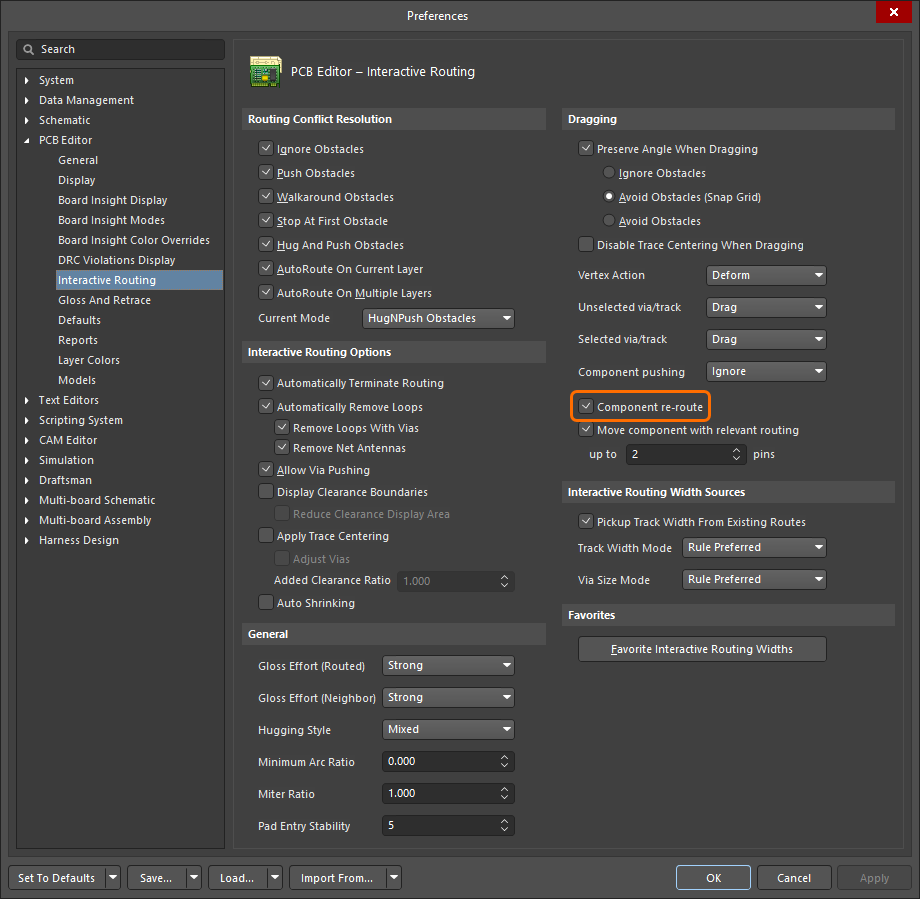
Component re-routeオプションが有効になっていると、移動するコンポーネントが配置された後に接続されたルートが復元されます。
この機能の重要な要件は、ファンアウトとエスケープ配線を保持することです。これをサポートするために、Shift+Tabショートカットを使用して、以下に詳述されているように、移動されるオブジェクトの可能なセットをサイクルします。
移動プロセス中、以下のショートカットを使用してオプションを制御できます:
-
Component Re-route Mode(Shift+R) - 再配線モードのオン/オフを切り替えます。移動セットが解放された後、ソフトウェアは切断されたネットを再接続するためにコンポーネントを再配線しようとします。Shift+Rショートカットを使用して再配線動作を抑制するか(またはComponent re-routeオプションをPreferencesダイアログのPCB Editor - Interactive Routingページで無効にします)。現在の Component Re-routeステータスは、ヘッズアップディスプレイとステータスバーに表示されます。
-
Change Component Selection(Shift+Tab) - ドラッグ中に、移動されるオブジェクトのセットを変更することができます。次の選択セットをサイクルするにはShift+Tabを押します:
-
Change Gloss Effort(Ctrl+Shift+G) - コンポーネント再配線中に適用されるグロスの量を制御するために、利用可能な配線グロス努力オプションをサイクルします。
Move component with relevant routingオプションをPreferencesダイアログのPCB Editor - Interactive RoutingページのDragging領域で有効にして、関連する配線(コンポーネント + ビアファンアウト + エスケープ + インターコネクト)を持つコンポーネントの移動アクションを開始します。前のセクションで説明されているように、選択セットをサイクルするにはShift+Tabショートカットを使用します。以下のup to xx pinsフィールドにピンの数を指定します。このフィールドで指定されたピン数よりも多いピンを持つコンポーネントの場合、Move component with relevant routingオプションは「機能しない」ことになり、関連する配線はコンポーネントと一緒に移動されません。

Move component with relevant routingオプションを無効にして、選択されたコンポーネントのみでMoveコンポーネントアクションを開始します。移動が始まる前に関連配線オブジェクトのセットが検出されるため、オプションが無効になっているときはShift+Tabを使用して選択セットを切り替えることができません。
Move Componentの動作を配線に優しくするために、ソフトウェアは移動配線と既存の配線の両方で違反を検出し修正します。違反のデフォルトの取り扱いは、移動中にそれらを視覚化し、ドロップ時に解決を試みることです。違反は既存の配線を押し出すことで解決されます。解決できない違反はそのまま残されます。
移動中のコンポーネントのパッドが同じネットのオブジェクトとどのように接続されるべきかをより良く制御するために、Nキーを使用してネットライン接続モードをサイクルできます。次のモードがサポートされています:
現在のネットライン接続モードは、コンポーネントが移動されるとヘッズアップディスプレイ(HUD)に表示されます。

配線のクリアとクリーニング
Backspaceキーには、選択された終端オブジェクト(コンポーネントのないトラック、アーク、ビア、またはパッド)を選択的に削除するのに役立つ便利な動作があります。個別のオブジェクトが選択され、そのオブジェクトが他のオブジェクトにのみ接触している場合、Backspaceキーを押すと、選択されたオブジェクトが削除され、接触しているオブジェクトが選択されます。再度Backspaceキーを押すと、そのオブジェクトが削除され、接触しているものが選択されます。必要な場所まで戻るためにBackspaceキーを押し続けます。
選択されたオブジェクトがそれに接触しているオブジェクトが複数ある場合、オブジェクトは削除されます(Deleteキーを使用するかのように)Backspaceキーを押したときに接続された配線オブジェクトは選択されません。

Backspaceキーを使用してセグメントを削除し、最後に接触したセグメントを選択します。
現在のドキュメント上で一つ以上の選択された配線オブジェクトを削除し、それらが削除されたものに接続されているすべての配線オブジェクトを自動的に選択するには、Ctrl+Deleteキーボードショートカットを使用できます。このコマンドを繰り返し使用することで、両方向に配線パスを段階的に巻き戻すことができます。
ルート削除コマンド
ルートを削除するには、つまり配線されたトラックとビアを削除し、これらを論理的な接続に置き換えるには、メインメニューのRoute » Un-Routeサブメニューのコマンドを使用することもできます。
-
All - ボード上のすべての物理的接続をアンルートします。
-
Net - 指定されたネット内のすべての物理的接続をアンルートします。コマンドを起動すると、カーソルが十字線に変わります。アンルートしたいネットに属する配線接続(またはパッド)の上にカーソルを置いてクリックするか、Enterを押します。
ネットのパッドの位置やその配線接続のいずれかがわからない場合は、空きスペースをクリックすると、ネット名を求めるダイアログが表示されます。ネット名がわからない場合は、?と入力してOKをクリックすると、設計にロードされているすべてのネットをリストアップするNets Loadedダイアログが起動します。ダイアログで選択したネットの物理的接続は、OKをクリックするとアンルートされます。
-
Connection - 二つのパッド間の物理的接続をアンルートします。コマンドを起動すると、カーソルが十字線に変わります。アンルートしたいトラックのセグメント(またはそれに接続されているパッドやビア)の上にカーソルを置いてクリックするか、Enterを押します。関連するパッドをクリックして接続をアンルートする場合、パッドに複数の接続があるときには、現在のレイヤーのトラックが最初にアンルートされ、次にレイヤースタックの順序(上層から下層へ)でトラックがアンルートされます。
-
Component - 指定されたコンポーネントのパッドから発生するすべての物理的接続をアンルートします。コマンドを起動すると、カーソルが十字線に変わります。物理的接続をアンルートしたいコンポーネントの上にカーソルを置いてクリックするか、Enterを押します。
コンポーネントの位置がわからない場合は、空きスペースをクリックすると、コンポーネントの指定子を求めるダイアログが表示されます。指定子がわからない場合は、?と入力してOKをクリックすると、設計内のすべてのコンポーネントをリストアップするComponents Placedダイアログが起動します。ダイアログで選択したコンポーネントの物理的接続は、OKをクリックするとアンルートされます。
トラックは、コンポーネントのパッドから次の目的地のパッドまでアンルートされます。この目的地のパッドの反対側のトラックは配線されたままです。
カーソルの下にあるコンポーネントのパッドから発生するすべての物理接続をアンルートすることもでき、コンポーネントを右クリックしてコンテキストメニューからComponent Actions » Unroute Componentコマンドを選択します。
-
Room – 特定のルームに関連するすべての物理接続を配線解除します。コマンドを実行すると、カーソルがクロスヘアに変わり、ルームを選択するように求められます。物理接続を配線解除したいルームの上にカーソルを置いてクリックするか、Enterキーを押します。ルームの外に延びる接続を配線解除するかどうかを尋ねるダイアログが表示されます。Yesをクリックすると、そのルーム内に存在するか、ルームに出入りするすべてのトラック(およびビア)が削除され、論理接続に置き換えられます。Nをクリックすると、ルームの中に完全に含まれるパッド間接続のみが配線解除されます。
トラックがルームの境界を越える場所では、トラックはルームのコンポーネントパッドからルームの外の次の目的地パッドまで経路を外されています。この目的地パッドの反対側のトラックは、経路が維持されます。
カーソルの下にあるルームに関連するすべての物理接続を解除するには、ルームを右クリックし、コンテキストメニューからRoom Actions » Unroute Roomコマンドを選択します。
-
ト ラックまたは経路のプリミティブがロックされている場合、ロックされたプリミティブのアンルートを許可するかどうかを尋ねる確認ダイアログが表示されます。Noを選択すると、ロックされていないトラックと経路プリミティブのみがアンルートされます。
-
既存の配線を削除するために、Route » Un-Routeコマンドのいずれかを使用することに加えて、トラックセグメントを選択して削除する方が迅速であることが多いです。配線を選択するためのヒントや 技術については、配線選択の戦略ページをチェックしてください。
ネットクリーンコマンド
不要な重複(重なった)トラックセグメントのために、すべてのネットまたは個別の配線ネットを清掃するには、メインメニューからそれぞれDesign » Netlist » Clean All Nets、Design » Netlist » Clean Single Netsコマンドを使用できます。すべてのネット(または選択したネット)が分析され、重なったトラックセグメントのすべてのインスタンスが解決され、冗長なセグメントが削除されます。このコマンドは、同じプロパティ(すなわち、同じレイヤー、同じ幅など)を持つ重なったトラックセグメントにのみ機能します。
オートルーターは、配線が完了した後、自動的にこのコマンドを開始します。
