PCB設計では、設計に対して/設計から生成できる出力の種類が非常に多く、各出力タイプにはそれぞれ固有の設定があります。この多数の出力を管理する最適な方法は、Output Jobファイル(一般に「OutJob」と呼ばれます)を使用することです。
OutJobは、あらかじめ構成された出力のセットです。各出力はそれぞれ独自の設定と出力形式(例:ファイルへの出力、プリンタへの出力)で構成されます。これらの出力設定はOutJobファイルに保存され、OutJobファイルはプロジェクトの一部となるASCIIファイルです。
OutJobは非常に柔軟で、必要に応じて出力を多くも少なくも含められ、プロジェクトには任意の数のOutJobを含めることができます。最適な運用としては、プロジェクトから生成する出力の用途ごとに、必要な出力一式を1つのOutJobにまとめて構成することです。たとえば、基板(裸基板)製造に必要な出力は1つのOutJobに、実装に必要な出力は2つ目のOutJobに、という具合です。
OutJobには、ERCやDRCレポートなどの検証系チェックも含めることができます。これらのレポートは、出力生成直前の最終確認(OKサイン)として有用であり、設計がリリース可能な状態であったことの記録として保持できます。
OutJobは可搬性が高く、Output Jobファイルをあるプロジェクトから次のプロジェクトへコピーし、必要に応じてData Sourceをリセットすることで、設計間で再利用することもできます。
まとめると、OutJobを使用することには次のような利点があります。
-
すべての出力を単一の場所で設定し、そこから生成できます。
-
必要に応じて複数の出力を1つの出力ファイルにまとめられます。たとえば、回路図の印刷とPCBレイアウトの印刷を同じPDFに出力できます。
-
OutJobはWorkspaceプロジェクトで使用でき、設計の管理されたリリースが可能になります。
-
OutJobファイルをプロジェクト間でコピーできるため、会社で推奨する出力設定を常に確実に使用できます。
Outjobの追加と定義
OutJobはOutputJobエディタで定義します。新しいOutput Jobファイルは次の方法で作成します。
-
File » New » Output Job File コマンドを使用します。
-
Projects パネルでプロジェクト名を右クリックし、表示されるポップアップメニューからAdd New to Project » Output Job File を選択します。
Output Jobファイルをプロジェクトに追加すると、ProjectsパネルのSettings\Output Job Filesサブフォルダ配下に表示されます。
Workspace Outjobの作成
接続しているWorkspace内で、Workspaceホストのコンテンツを活用してOutput Jobを作成することもできます。
-
PreferencesダイアログのData Management – Templates pageのTemplatesタブを開きます。
-
Addボタンのメニュー、またはテンプレートグリッドのコンテキストメニューからOutput Jobコマンドを選択します。

-
コマンドを選択したら、開いたClose PreferencesダイアログでOKをクリックしてPreferencesダイアログを閉じ、テンポラリのOutputJobエディタを開きます。新しいOutput Jobの計画リビジョンが、Output JobsタイプのWorkspaceフォルダに自動的に作成されます。
-
このページの後半で説明するように、必要に応じてOutput Jobを構成します。
-
メインメニューからFile » Save to Serverコマンドを選択して、Output Jobを接続中のWorkspaceに保存します。Edit Revisionダイアログが表示され、Workspaceで作成するOutput JobのNameおよびDescriptionを定義でき、必要に応じてリリースノートも追加できます。
既存のローカルOutput JobをWorkspaceに保存
既存のOutput Jobファイル(*.OutJob)がある場合、このファイルを直接Workspaceに保存することもできます。手順は次のとおりです。
-
Altium DesignerでOutput Jobファイルを開きます。
-
メインメニューからFile » Save to Serverコマンドを選択します。
Workspaceに保存する前に、ファイルはローカルに保存(File » Save)されている必要があります。
-
Choose Planned Item Revisionダイアログが表示されます。これを使用して、ファイルを保存する対象のWorkspace Output Job(次のリビジョン、またはPlanned状態の確立済みリビジョン)を選択し、OKをクリックします。
対象のWorkspace Output Jobが存在しない場合は、Choose Planned Item Revisionダイアログ上でその場で作成できます。ダイアログのリビジョン一覧領域で右クリックする(または、フォルダにまだアイテムがない場合はAdd an itemコントロールをクリックする)ことで、Create Item » Outputjobコマンドを選択します。この方法で作成する場合は、(Create New Itemダイアログの)Open for editing after creationオプションを必ず無効にしてください。そうしないと、直接編集モードに入ります。
-
Edit Revisionダイアログが表示され、Name、Descriptionを定義し、必要に応じてリリースノートを追加できます。
-
OKをクリックすると、ファイルが保存され、Workspace Output Jobの該当リビジョンに格納されます。
Workspaceに保存したいOutput JobファイルがLocal Template folder(PreferencesダイアログのData Management – Templates page下部に示されます)にあり、テンプレートグリッドのLocalエントリ配下に一覧表示されている場合は、それを右クリックしてMigrate to Serverコマンドを選択することで、新しいWorkspace Output Jobへ移行できます。Template migrationダイアログでOKボタンをクリックして移行プロセスを進めます。このダイアログに記載されているとおり、元のプロジェクトファイルはローカルテンプレートフォルダ内のZipアーカイブに追加され(そのためLocalテンプレートリストには表示されなくなります)。
Workspace Output Jobの編集
いつでもWorkspace内のOutput Jobに戻って編集できます。PreferencesダイアログのData Management – Templates pageのTemplatesタブから、Output Jobエントリを右クリックし、コンテキストメニューからEditコマンドを選択します。テンポラリエディタが開き、Workspace Output Jobの最新リビジョンに含まれるOutput Jobが編集用に開かれます。必要な変更を行い、その後、Workspace Output Jobの次のリビジョンにOutput Jobを保存します。
Workspace Output Jobをプロジェクトに追加
Workspace Output Jobは設計プロジェクトで使用できます。
Project OptionsダイアログのManaged OutputJobs tabから、使用するWorkspace Output Jobのリビジョンを選択します。 ボタンをクリックするとSelect configuration item (Output Jobs)ダイアログが表示され、利用可能なWorkspace内のすべてのOutput Jobの最新リビジョンが一覧表示されます。必要なOutput Jobを選択してOKをクリックします。

Project OptionsダイアログのManaged OutputJobsタブ内から、outputjobのリビジョンを手動で選択します。
Options and Controls of the Select configuration item (Output Jobs) Dialog
Grid - 利用可能な構成アイテムは、Name、Description、Item Revision、Revision Stateの観点で一覧表示されます。リストから目的の構成アイテムを選択し、OKをクリックして、選択したアイテムをProject OptionsダイアログのManaged OutputJobs tabに追加します。
右クリックメニュー
必要に応じて、異なるOutput Jobの追加リビジョンを引き続き追加します。Project Optionsダイアログを終了するためにOKをクリックすると、選択したoutputjobがProjectsパネルに表示されます。Workspace OutputJobは、Projectsパネル内で アイコンにより識別されます。

追加したoutputjobのリビジョンはProjectsパネルに反映されます。
Using a Workspace Output Job as Part of an Environment Configuration
Workspace Output Jobは、1つ以上定義されたEnvironment Configurationsの構成データアイテムとして使用することもできます。環境構成は、設計者の作業環境を会社で承認された設計要素のみを使用するように制約するために用いられます。環境構成は、Workspaceを通じて提供されるサービスであるTeam Configuration Center内で定義・保存されます。
Workspace に接続し、(該当する場合)利用可能な環境構成の選択肢から選択すると、Altium Designer は Output Job Configuration の使用に関して構成されます。選択した環境構成に 1 つ以上の outputjob リビジョンが定義されている場合、onlyそれらの定義済み構成を使用できます。該当する環境構成に outputjob リビジョンが指定/追加されていない場合、これらは手動で定義可能なままになります。つまり、Workspace ベースの Output Job Configuration を手動で再利用したり、ローカルテンプレートを使用したりできます。詳細は Environment Configuration Management(Altium 365 Workspace、Enterprise Server Workspace)を参照してください。
環境構成の強制(enforcement)下では、Altium Designer は Output Job の使用に関して、次の領域で構成されます。
Workspace Output Job をプロジェクトに追加して開くと、OutputJob エディタにはそのファイルが Managed OutputJob Documentであることが反映され、Item Revision、その説明、そしてその Output Job が存在する親 Workspace が示されます。

Workspace Output Job を表示しているときの Output Job Editor。
Workspace Output Job の場合、何らかの形で変更に影響する可能性のあるコントロールは無効化されます。そのため、次の操作は ARE NOTできません。
-
新しい Output Generator の追加。
-
既存 Output Generator の設定。
-
既存 Output Generator の切り取り、コピー、貼り付け、複製、削除。
-
新しい Output Container または Hard Copy Job の追加。
-
既存 Output Container または Hard Copy Job の設定。
-
既存 Output Container または Hard Copy Job の切り取り、コピー、貼り付け、削除。
-
有効な Output Container または Hard Copy Job に対する Output Generator の含有状態(inclusion state)の切り替え。
ただし、OutJob のバリアント使用は引き続き指定できます。
エディタのメイン
Outputs 領域内の任意の場所を右クリックし、コンテキストメニューから
Document Options を選択します。
![]() Document Options dialog
Document Options dialog が開き、選択した OutputJob ファイルに関する情報(使用している Outputjob Item のリビジョン、ライフサイクル状態、最新リビジョンかどうか)が表示されます。また、その OutputJob が存在するソース Workspace も表示されます。
Show in Explorer ボタンをクリックすると
Explorer パネルにアクセスでき、Outputjob のリビジョンが読み込まれた状態で表示されます。
OutJob の要素
OutJob の構成には 3 つのステップがあります。

OutJob を構成する要素はすべて OutputJob Editor 内で定義・管理されます。
-
Add and configure the required outputs – 出力は、Assembly Outputs、Fabrication Outputs、Report Outputs などの機能カテゴリにまとめられます。厳密には、出力は関連付けられた Output Generator を適切に設定し、プロジェクト内の指定ドキュメント(またはプロジェクト自体)をデータソースとして実行することで取得されます。
-
Add and configure the required output formats – 任意の出力タイプを生成するには、その出力を対応する(かつ適用可能な)出力フォーマットにマッピングする必要があります。これは、サポートされている Output Containers(PDF、Folder Structure、Video)のいずれか、または Hard Copy(印刷ベースの出力)として扱われます。複数の出力を同一のコンテナまたはハードコピーにマッピングでき、出力の生成先や生成方法(コンテナ/ハードコピーに関連するメディア関連オプション)をユーザーが制御できます。
-
Set the variant choice – Altium Designer では、PCB プロジェクトの出力をベース(バリアントなし)の設計で生成することも、定義済みバリアントの使用を指定して生成することもできます。適用可能な出力ごとにバリアントを選ぶか、ファイル内の適用可能なすべての出力に適用する単一のバリアントを選択します。
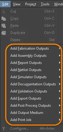
OutJob への出力の追加
カテゴリ下部の該当する Add New [type] Output テキストをクリックし、ポップアップメニューから必要な出力タイプを選択して、必要なタイプの新しい出力を追加します。あるいは、メイン Edit menu から該当コマンドを選択します。

適切な Data Source を選択して、必要な各出力を追加します。
プロジェクト内に適切なソースデータが存在する出力タイプは使用可能として一覧表示され、それ以外の出力タイプは使用不可(グレーアウト)として表示されます。
2 つ目のメニューでは Data Source、つまり出力生成時に使用するソースドキュメントを指定できます。各出力に対して適用可能なデータソースのみが利用可能となるため、ミスの余地が小さくなります。
Data Source は出力の種類によって異なります。PCB Prints、Gerber Files、Testpoint Reports などの PCB 関連出力は、PCB 設計ドキュメントを Data Source として使用します。BOM の Data Source は、特定の単一ソース回路図ドキュメント、PCB 設計ドキュメント、またはすべてのソース回路図ドキュメントになり得ます。最後のものは [Project] エントリで表されます。
Data Source は、出力を追加した後のどの段階でも変更できます。現在の Data Source をクリックするとドロップダウン矢印が表示されるので、一覧から別のソースを選択します。
特定の出力では、Data Source の一覧に [Project Physical Documents] が含まれます。物理設計(基板上で実装される設計)を、論理設計(元の回路図)とは異なる形でアノテーションする必要がある場合にこのオプションを使用します。これは、設計に Device Sheets が含まれる場合、またはマルチチャネル機能を使用していて、単純なフラットなアノテーション方式が望ましい場合に必要になります。
「Project Physical Documents」という用語は、回路図の物理(compiled)ビューを指します。
Schematic Prints 出力の Data Source を設定する際、All SCH Documents はプロジェクト内のすべての論理回路図セット(未コンパイルの「Editor」ビューの各回路図)を印刷することに対応します。プロジェクト内のすべての物理回路図セット(各回路図の compiled ドキュメントビュー)を印刷するには、Data Source を [Project Physical Documents] に設定してください。
出力リストを作成するには、Edit main menu(または Help » Right Mouse Click Output Medium サブメニュー、あるいは Job Manager Toolbar toolbar)から Cut、Copy、Paste、Duplicate 、Delete コマンドを使用するか、Outputs 領域の右クリックメニューを使用することもできます(標準の複数選択操作 Ctrl+click、 Shift+click により複数出力を選択可能)。
なお、OutputJob ドキュメントにおける通常の切り取り/コピー操作では Windows クリップボードは使用されません。代わりに、このドキュメントタイプ専用の内部クリップボードが維持されます。また、OutputJob の内部クリップボードは、ソフトウェア内の他のエディタが使用する内部クリップボードとは完全に独立しています。切り取り/コピーと貼り付けは、OutputJob ドキュメント間、または同一 OutputJob ドキュメント内でのみ行えます。
再利用性の最大化 – Output Job を汎用化する
出力を構成する際、結果として得られる Output Job Configuration を可能な限り汎用的にするための革新的な機能が多数用意されています。OutJob を汎用のままにしておくことで、将来の設計プロジェクト全体にわたって再利用できる可能性を効果的に最大化できます。
Generic Data Source Names
多くの output generator は、適用される出力データを生成するソースとして、特定名の基盤ドキュメントを使用します。たとえば、PCB ドキュメント FluxTriangulator.PcbDoc から生成される Gerber ファイルなどです。しかし、この方法では Output Job Configuration がそのドキュメントの親設計プロジェクトでしか有用でなくなってしまいます。特定性を避けるため、多くの output generator で、基盤となる Data Source に対して汎用エントリを選択できるようになっています。次の表は、対応している output generator と、利用可能な汎用エントリ(複数可)をまとめたものです。
| カテゴリ |
出力タイプ |
汎用データソースエントリ |
| ネットリスト出力 |
すべて |
[Project] |
| シミュレータ出力 |
Mixed Sim
SIMetrix
SIMPLIS |
[Project] |
| ドキュメント出力 |
複合
PCB 3D印刷
PCB 3Dビデオ
PCB印刷
PDF3D |
[PCB Document] |
| |
PDF3D MBA |
[MBA Document] |
| |
回路図印刷 |
[Project Physical Documents] |
| アセンブリ出力 |
すべて |
[PCB Document] |
| 製造出力 |
すべて |
[PCB Document] |
| レポート出力 |
部品表 |
[Project]
[ActiveBOM Document] |
| |
コンポーネント相互参照
コメントのエクスポート
プロジェクト階層レポート
単一ピンネットのレポート |
[Project] |
| 検証出力 |
BOMチェック |
[ActiveBOM Document] |
| |
コンポーネント状態
構成コンプライアンス
電気ルールチェック
|
[Project] |
| |
デザインルールチェック
差分レポート
フットプリント比較レポート |
[PCB Document] |
| エクスポート出力 |
Ansoft Neutral (AutoPCB)
Ansys EDB
AutoCAD dwg/dxf PCB
IDFのエクスポート
PARASOLIDのエクスポート
STEPのエクスポート
VRMLのエクスポート
Hyperlynx (AutoPCB)
MathWorks (AutoPCB)
P-CAD ASCII (AutoPCB)
名前を付けて保存/PCBのエクスポート
Specctra Design PCB |
[PCB Document] |
| |
MBA PARASOLIDのエクスポート
MBA STEPのエクスポート |
[MBA Document] |
| |
AutoCAD dwg/dxf 回路図
OrCAD v7 Capture Design (AutoSCH)
P-CAD V16 Schematic Design (AutoSCH)
名前を付けて保存/回路図のエクスポート |
[Project] |
| ポストプロセス出力 |
ファイルのコピー |
[Project] |
Layer Classes
次の出力ジェネレータについて、構成に名前付きのレイヤークラスを追加できます。
-
PCB印刷
-
アセンブリ図面
-
ドリル図面
-
最終
-
Gerberファイル
-
マスクセット
-
電源プレーンセット
これにより、これらの出力ジェネレータを汎用的に再利用できるようになります。たとえば「signal layers」というクラスを追加してOutJobで参照すると、「signal layers」クラスを持つ任意の設計は、変更なしでその出力ジェネレータを使用できます。
出力の設定
出力タイプによっては、関連する出力ジェネレータを設定するためのオプションが用意されており、生成される出力をより細かく制御できます。設定オプションが利用可能な場合、次のいずれかの方法でアクセスできます。
-
必要な出力の行を直接ダブルクリックする。
-
必要な出力を右クリックし、コンテキストメニューからConfigure を選択する。
-
必要な出力を選択し、キーボードショートカットAlt+Enterを使用する。
-
必要な出力を選択し、 Edit » Configureコマンドを選択する。
複数の出力を選択している場合、最後に選択した(現在フォーカスされている)出力に関連付けられた設定ダイアログが表示されます。
コマンドを起動すると、関連する設定ダイアログが表示されます。ダイアログを使用して、生成したい特定の出力ファイルのセットアップオプションを定義します。定義したオプションは、次回その出力を生成する際に使用されます。

出力ジェネレータごとに、生成内容を正確に設定するための固有のダイアログがあります。
ダイアログの種類(そもそも設定ダイアログが表示されるかどうかも含む)は、選択した出力によって異なります。データを直接生成する出力では、このコマンドを使用してもダイアログは表示されません(例:Design Rules Checkの検証レポート生成)。
ハードコピー(印刷デバイスに送られる印刷出力)を生成できる出力については、ページプロパティを定義するためのダイアログにもアクセスできます。出力を右クリックしてコンテキストメニューから
Page Setupを選択するか、出力を選択して
File » Page Setupコマンドを使用します。
利用可能な出力タイプ
以下は、利用可能な出力タイプの概要です。該当する場合、特定の出力の設定方法を説明する関連ドキュメントへのリンクが含まれています。
Netlist Outputs
ネットリストは、設計内のコンポーネント間の論理的な接続性を記述したもので、設計を他の設計プラットフォームへ移行する際に有用です。多種多様なネットリスト形式が利用できます。
Simulator Outputs
SPICEネットリストは、回路をテキストで表現したものです。アクティブなOutputJobファイルにネットリスト出力を追加するには、メインのジョブ設定ウィンドウのSimulator Outputs 領域下部にある[Add New Simulator Output] コントロールに関連付けられたメニュー、またはEdit » Add Simulator Outputs サブメニューからコマンドを選択します。
Documentation Outputs
-
PCB印刷 - 任意の数の印刷物(ページ)を、任意のレイヤー配置およびプリミティブ表示で設定できます。アセンブリ図面などの印刷出力を作成するために使用します。
-
PCB 3D印刷 - 3次元ビュー視点から見た基板のビュー。
-
PCB 3Dビデオ - PCBエディタのPCB 3D Movie Editorパネルで定義された3Dキーフレームのシーケンスに基づき、基板の簡易ビデオを出力します。
-
PDF 3D - Adobe Acrobat®でのズーム、パン、回転を完全にサポートした、基板の3D PDFビューを生成します。PDFにはモデルツリーが含まれ、ネット、コンポーネント、シルクスクリーンの表示を制御できます。
-
回路図印刷 - 設計で使用される回路図図面。
-
Draftsman - プロジェクトに追加されたDraftsman図面。
Assembly Outputs
Fabrication Outputs
Report Outputs
BOM、プロジェクト階層レポート、プロジェクトコメントPDFなど、多数のレポートをプロジェクトまたはそのドキュメントのいずれかに対して作成できます。
-
部品表 – 基板の製造に必要な部品と数量(BOM)のリストを、さまざまな形式で作成します。
-
コンポーネント相互参照レポート – 設計内の回路図図面に基づいてコンポーネントのリストを作成します。
-
Report Project Hierarchy – プロジェクトで使用されているソースドキュメントの一覧を作成します。
-
Report Single Pin Nets – 接続が1つしかないネットを一覧化したレポートを作成します。
詳細は Preparing Reports ページを参照してください。
Validation Outputs
本ソフトウェアには多数の検証チェックが含まれており、出力生成時に出力として含めることができます。各チェックはHTMLレポートファイルを生成します。
これらの検証レポートの設定はOutputJobに保持されます。ソフトウェア内の別の場所で検証チェックを設定した場合、その設定は該当ファイルに保持されます。たとえば、プロジェクトのエラーチェック設定はプロジェクトファイルに、PCB DRC設定はPCBファイルに保存されます。
Export Outputs
PostProcess Outputs
この出力タイプでは、Altium Designerネイティブではないファイル形式を出力の一部として含めることができます。プロジェクトのディレクトリ構造内にある対象ファイルを、設定済みのFolder Structure出力コンテナで指定されたフォルダへコピーします。
詳細は Preparing PostProcess Outputs ページを参照してください。
出力形式の定義
OutJobの出力を追加して設定することで、what生成する内容とhow生成方法が定義されます。生成された出力を書き込む先、すなわちどの形式で出力を生成するかの定義が必要です。生成する出力の種類に応じて、これは Output Containers と Hard Copy の組み合わせで扱われます。
出力コンテナ
出力は(該当する場合)3種類の出力コンテナに書き込めます。PDF、特定形式の出力ファイル(Gerberファイルなど)、またはビデオです。
新規OutJobには、これら各タイプのコンテナが1つずつ、PDF、Folder Structure、Videoという名前でデフォルト追加されます。これらのタイプのコンテナは、[Add New Output Container] をクリックするか、 Edit » Add Output Medium サブメニューから任意の数だけ追加でき、識別しやすいように名前を編集できます。
新しい出力コンテナは、適用可能な出力を1つ以上選択し、その選択を Output Containers または Hard Copy 領域へドラッグ&ドロップして(既存の定義済み出力コンテナから離れた場所に)作成することもできます。出力は自動的にリンクされます。
出力コンテナの一覧を作成するには、メインメニューの Help » Right Mouse Click Output Medium サブメニュー、または Output Containers もしくは Hard Copy 領域の右クリックメニューから、Cut、Copy、Paste 、Delete コマンドを使用することもできます。
Paste As コマンドを使用すると、Output Job Editorのクリップボードに現在ある内容に基づいて新しい出力コンテナを作成できます。これらのコマンドは、クリップボード上の内容に互換性がある場合にのみ利用できます。たとえば、コピーした印刷ジョブ、PDF出力コンテナ、Folder Structure出力コンテナ(関連する出力がPDF化できる場合)、またはPDF化できるコピー済み出力のみが、新しいPDF出力コンテナとして貼り付け可能です。
なお、本ソフトウェアはOutputJobドキュメントにおける通常の切り取り/コピー/貼り付け操作でWindowsクリップボードを使用しません。代わりに、このドキュメントタイプ専用の内部クリップボードが維持されます。また、OutputJobの内部クリップボードは、ソフトウェア内の他のエディタが使用する内部クリップボードとは完全に独立しています。切り取り/コピー/貼り付けは、OutputJobドキュメント間、または同一OutputJobドキュメント内でのみ行えます。

出力コンテナは生成された出力を「受け取る」先です。
コンテナの設定
コンテナをクリックすると、コンテナを設定する機能を含む追加のコントロールにアクセスできます。必要なコンテナをクリックした後、Change リンクをクリックして、そのコンテナタイプに関連付けられた Settings ダイアログにアクセスします。
-
PDF出力コンテナの場合、PDF Settings ダイアログが表示されます。

Advanced と Basic の PDF Settings ダイアログのバリエーション
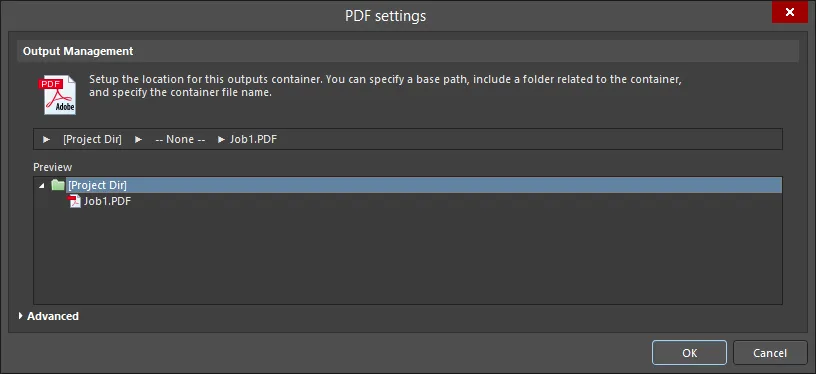
Options and Controls of the PDF Settings Dialog
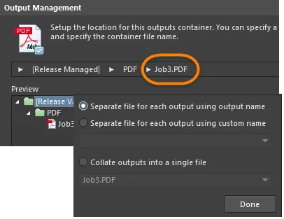
出力管理
この領域を使用して、この出力コンテナの保存場所を設定します。パスの指定、コンテナに関連するコンテナフォルダの含有、コンテナのファイル名の指定ができます。
以下で説明するウィンドウは、右下隅をドラッグすることで水平方向にサイズ変更できます。
-
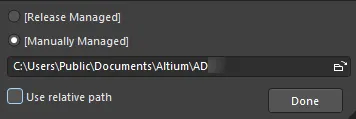
Release Managed - クリックするとポップアップが開き、フォルダ管理を指定できます。
-
Release Managed - PDFをPCBリリースシステムで利用可能にするには選択します。
-
Manually Managed - PDFを手動管理とし、ローカルフォルダに保存するには選択します。デフォルトでは、Project Optionsダイアログの Options タブの Output Path フィールドで指定されたパスになります。
-
File Location textbox - ファイルブラウザボタンをクリックして、PDFの保存先フォルダを参照・選択します。このオプションは Manually Managed が選択されている場合にのみ利用できます。
-
Use relative path - このオプションを有効にすると、File Location textbox で相対パスを使用します。 このオプションは Manually Managed が選択されている場合にのみ利用できます。
-
Done - クリックして設定を完了します。
-
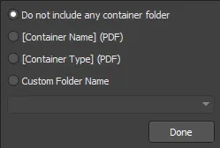
None - クリックするとポップアップが開き、PDFのコンテナフォルダを設定できます。
-
Do not include any container folder - コンテナフォルダを含めない場合に選択します。
-
[Container Name] (PDF) - コンテナ名をコンテナフォルダ名として使用するには選択します。
-
[Container Type] (PDF) - コンテナタイプをコンテナフォルダタイプとして使用するには選択します。
-
Custom Folder Name - フォルダ名をカスタマイズするには選択します。ドロップダウン矢印をクリックしてドロップダウンリストを開き、フォルダの命名文字列を選択できます。テキストボックスにフォルダ名を直接入力することもできます。
-
Done - クリックして設定を完了します。
-
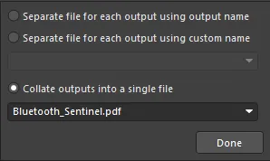
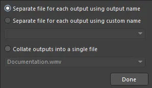
[Filename].pdf - クリックするとポップアップが開き、PDF出力を設定できます。
-
Separate file for each output using output name - 指定された出力名を使用して、各出力ごとに個別ファイルを作成するには選択します。
-
Separate file for each output using custom name - 下のテキストボックスで指定したカスタム名を使用して、各出力ごとに個別ファイルを作成するには選択します。ドロップダウン矢印をクリックしてドロップダウンリストを開き、命名文字列を選択できます。テキストボックスにカスタム名を直接入力することもできます。
-
Collate outputs into a single file - 出力を1つのファイルにまとめるには選択します。 ドロップダウン矢印をクリックしてドロップダウンリストを開き、ファイルの命名文字列を選択できます。テキストボックスにカスタム名を直接入力することもできます。
-
Done - クリックして設定を完了します。
-
Preview - この領域にはPDFの保存場所のプレビューが表示されます。上記のポップアップダイアログで変更を行うとプレビューウィンドウが更新され、変更がフォルダ構造にどのように影響するかを即座に確認できます。
高度なバージョンコマンド
-
Zoom - スライダーバーを使用してズームレベル(Far~Close)を制御し、コンポーネントまたはネットへジャンプする際の表示倍率を調整します。
-
Page Size And Orientation - これらの設定を使用して、ページサイズと向きを Page Setup dialog から設定するか、ソースドキュメントから設定するかを制御します。
-
Schematic Page Size and Orientation Source - ドロップダウンリストから Page Setup Dialog または Source Document のいずれかを選択し、回路図ドキュメントに使用するページサイズおよび向きの設定元を指定します。
-
PCB Page Size and Orientation Source - ドロップダウンリストから Page Setup Dialog または Source Document のいずれかを選択し、PCBドキュメントに使用するページサイズおよび向きの設定元を指定します。
-
Output Options
-
Additional Bookmarks
-
Generate nets information - 有効にすると、PDFファイルにネット情報を含めます。このオプションを有効にすると、次のオプションが利用できます。
-
Pins - 有効にすると、PDFファイル内でピンをブックマークします。
-
Net Labels - 有効にすると、PDFファイル内でネットラベルをブックマークします。
-
Ports - 有効にすると、PDFファイル内でポートをブックマークします。
-
Global Bookmarks for Components and Nets - 有効にすると、PDFファイル内のすべてのコンポーネントおよびネットに対してブックマークを作成します。
追加コントロール
-
Advanced/Basic - クリックして、ダイアログの Advanced 版と Basic 版を切り替えます。
-
Folder Structure 出力コンテナの場合、Folder Structure Settings ダイアログが表示されます。

Advanced 版および Basic 版の Folder Structure settings ダイアログ
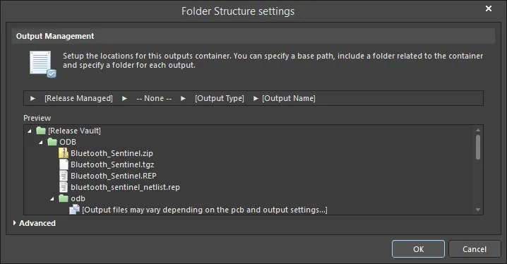
Options and Controls of the Folder Structure Settings Dialog
出力管理
この領域を使用して、この出力コンテナの保存場所を設定します。ベースパスを指定し、コンテナに関連するフォルダを含め、コンテナのファイル名を指定できます。
-
Release Managed - クリックして、フォルダ管理を指定できるポップアップを開きます。
-
Release Managed - 選択すると、PCBリリースシステムでファイルを利用可能にします。
-
Manually Managed - 選択すると、ファイルを手動管理としてローカルフォルダに保存します。デフォルトでは、Project Options dialog の Options タブにある Output Path フィールドで指定されたパスになります。.
-
File Location textbox - フォルダアイコンをクリックして、ファイルの保存先フォルダを参照します。このオプションは Manually Managed が選択されている場合にのみ使用できます。
-
Use relative path - このオプションを有効にすると、File Location textbox で相対パスを使用します。 このオプションは Manually Managed が選択されている場合にのみ使用できます。
-
Done - クリックして設定を完了します。
-
None - クリックして、コンテナフォルダを設定できるポップアップを開きます。
-
Do not include any container folder - 選択すると、コンテナフォルダを含めません。
-
[Container Name] (Folder Structure) - 選択すると、フォルダ名として Folder Structure を使用します。
-
[Container Type] (Generated Files) - 選択すると、フォルダタイプとして Generated Files を使用します。
-
Custom Folder Name - 選択すると、フォルダ名をカスタマイズします。ドロップダウン矢印をクリックしてリストを開き、フォルダの命名文字列を選択できます。また、テキストボックスにフォルダ名を直接入力することもできます。
-
Done - クリックして設定を完了します。
-
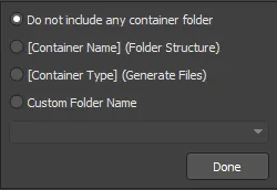
Output Type - クリックして、出力フォルダを設定するポップアップを開きます。

-
Do not include any output folder - 選択すると、出力フォルダを含めません。
-
Output Name - 選択すると、出力名を出力フォルダ名として使用します。
-
Output Type - 選択すると、出力タイプを使用します。
-
Custom prefix_[Output Type] - 選択すると、テキストボックスでカスタムプレフィックスを指定します。
-
Custom Folder Name - 選択すると、フォルダ名をカスタマイズします。ドロップダウン矢印をクリックしてリストを開き、命名文字列を選択できます。また、テキストボックスにカスタム名を直接入力することもできます。
-
Done - クリックして設定を完了します。
-
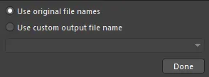
Output Name - クリックして、出力ファイル名を設定できるポップアップを開きます。
-
Use standard output file name - 選択すると、標準の出力ファイル名を使用します。
-
Use custom output file name - 選択すると、カスタム出力ファイル名を使用します。ドロップダウン矢印をクリックしてリストを開き、命名文字列を選択できます。また、テキストボックスにカスタム名を直接入力することもできます。
-
Done - クリックして設定を完了します。
-
Preview - この領域にはフォルダ構成のプレビューが表示されます。上記のポップアップダイアログで変更を行うとプレビューウィンドウが更新され、変更がフォルダ構成にどのように影響するかをすぐに確認できます。
詳細版コマンド
出力オプション
-
Open generated outputs - 有効にすると、生成後に出力を開きます。
-
Add generated files to project - 有効にすると、生成されたファイルをプロジェクトに追加します。ファイルは Projects panel の Generated サブフォルダ配下に表示されます。
-
Use the Output Name as the file name instead of the default - 有効にすると、デフォルト名ではなく指定した出力名を使用します。
-
Timestamp folder - 有効にすると、タイムスタンプフォルダを作成します。日付と時刻はシステム設定と同じ形式になります。
CAMtastic 自動ロードオプション
関連する出力をCAMtasticに自動ロードしたい場合は、次の出力タイプを有効にします。有効化された出力タイプは、バッチ生成が実行されるたびに新しいCAMtasticドキュメントへ自動ロードされます。
-
ODB++ Output
-
Gerber Output
-
NC Drill Output
-
IPC-356-D Output
上記オプションを定義すると、その設定は保持されます。つまり、次回 Output Generators を実行した際、生成された出力は別の新しいCAM Editorドキュメントにロードされます。既存のCAMドキュメントのみを更新できるようにしたい場合は、
Reset auto-load options after generation オプションを有効にします。これにより、初回生成後にすべての自動ロードオプションがクリア(無効化)されます。その後、CAM Editor の
Rescan および
Reload コマンド(
CAMtastic panel 内。
*.Cam ドキュメントがアクティブなときに利用可能)にアクセスでき、生成済みファイルと既存(インポート済み)ファイルのタイムスタンプ比較、および既存レイヤーへのデータロードを実行できます。
-
Reset auto-load option after generation - 有効にすると、出力生成後に自動ロードオプションをリセットします。
詳細/基本
クリックして、ダイアログの Advanced 版と Basic 版を切り替えます。
-
Video 出力コンテナの場合、Video Settings ダイアログが表示されます。

Advanced 版および Basic 版の Video settings ダイアログ
Options and Controls of the Video Settings Dialog
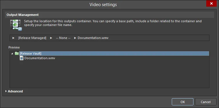
出力管理
この領域を使用して、この出力コンテナの保存場所を設定します。ベースパスを指定し、コンテナに関連するフォルダを含めたうえで、コンテナのファイル名を指定できます。
-
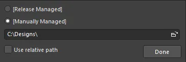
Release Managed - クリックするとポップアップが開き、フォルダ管理を指定できます。
-
Release Managed - 選択すると、ビデオをPCBリリースシステムで利用可能にします。
-
Manually Managed - 選択すると、ビデオを手動管理としてローカルフォルダに保存します。デフォルトでは、これはOutput Path プロジェクトオプションダイアログのOptionsタブにあるフィールドで指定されたパスになります。
-
File location field - 参照アイコンをクリックして、ビデオの保存先フォルダを参照します。このオプションは、Manually Managed が選択されている場合にのみ使用できます。
-
Use relative path - このオプションを有効にすると、File Location textboxで相対パスを使用します。 このオプションは、Manually Managed が選択されている場合にのみ使用できます。
-
Done - クリックして設定を完了します。
-
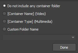
None - クリックするとポップアップが開き、コンテナフォルダを設定できます。
-
Do not include any container folder - コンテナフォルダを含めないように選択します。
-
[Container Name] (Video) - Video をフォルダ名として使用するように選択します。
-
[Container Type] (Multimedia) - Multimedia をフォルダタイプとして使用するように選択します。
-
Custom Folder Name - フォルダ名をカスタマイズするように選択します。ドロップダウン矢印をクリックしてリストを開き、フォルダの命名文字列を選択できます。テキストボックスにフォルダ名を直接入力することもできます。
-
Done - クリックして設定を完了します。
-
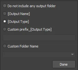
Output Type - クリックするとポップアップが開き、出力フォルダを設定します。
-
Do not include any output folder - 出力フォルダを含めないように選択します。
-
Output Name - 出力名を出力フォルダ名として使用するように選択します。
-
Output Type - 出力タイプを使用するように選択します。
-
Custom prefix_[Output Type] - このオプションを選択して、テキストボックスでカスタムプレフィックスを指定します。
-
Custom Folder Name - フォルダ名をカスタマイズするように選択します。ドロップダウン矢印をクリックしてリストを開き、命名文字列を選択できます。テキストボックスにカスタム名を直接入力することもできます。
-
Done - クリックして設定を完了します。
-
Separate file for each output - クリックするとポップアップが開き、出力ファイルの構成方法を指定します。
-
Separate file for each output using output name - 指定した出力名を使用して、各ビデオごとに個別ファイルを作成するように選択します。
-
Separate file for each output using custom name - カスタム名を使用して、各ビデオごとに個別ファイルを作成するように選択します。 ドロップダウン矢印をクリックしてリストを開き、命名文字列を選択できます。テキストボックスにカスタム名を直接入力することもできます。
-
Collate outputs into a single file - 出力を単一ファイルに結合するように選択します。 ドロップダウン矢印をクリックしてリストを開き、ファイルの命名文字列を選択できます。テキストボックスにファイル名を直接入力することもできます。
-
Done - クリックして設定を完了します。
Preview - この領域にはフォルダのプレビューが表示されます。 上記のポップアップダイアログで変更を行うとプレビューウィンドウが更新され、変更がフォルダ構造にどのように影響するかをすぐに確認できます。
高度なバージョンのコマンド
メディア設定
-
Type - ドロップダウンリストからメディアタイプを選択します:
-
Video (FFmpeg)
-
Video (Windows Multimedia)
-
Video (Windows Media Format)
すべてのビデオタイプ/フォーマットにおいて、エクスポートされるビデオはデフォルトのフレームレート25 fpsで生成されます。Windows Multimediaビデオでは、デフォルトで使用されるピクセルフォーマットは32です。FFmpegビデオ(全フォーマット)では、ピクセルフォーマットは編集できず、Planar YUV 4:2:0, 12bpp, (1 Cr & Cb sample per 2x2 Y samples)に設定されます。Windows Media形式のビデオにはピクセルフォーマットの定義がありません。
次の表は、現在サポートされているビデオタイプとフォーマットをまとめたものです:
Video Type
|
Supported File Format(s)
|
Video (FFmpeg)
|
3GP2 (*.3g2)
ASF (*.asf, *.wmv, *.wma)
ASF-Streaming (*.asf, *.wmv, *.wma)
AVI (*.avi)
Flash (*.swf)
FLV (*.flv)
MOV (*.mov)
MP4 (*.mp4)
|
Video (Windows Multimedia)
|
Windows Video file (*.avi)
|
Video (Windows Media Format)
|
Windows Media file (*.wmv, *.wma, *.asf)
|
-
Format - ドロップダウンリストからメディアフォーマットを選択します。このオプションは、Video (FFmpeg) が Type として選択されている場合にのみ使用できます。
-
Video Pixels - 上下矢印(またはテキストボックスに数値を直接入力)を使用して、希望するビデオのピクセル数を選択します。
出力オプション
-
Open after export - このオプションを有効にすると、エクスポート後にビデオを開きます。
-
Prompt if file already exists - このオプションを有効にすると、ファイルがすでに存在する場合にプロンプトを表示します。
詳細設定
-
Video Codec - ドロップダウンからオプションを選択します。このオプションは、Video (FFmpeg) またはVideo (Windows Media Format) がTypeとして選択されている場合にのみ使用できます。 次の表は、選択したビデオタイプ/フォーマットに基づいて利用可能なコーデックをまとめたものです。
ビデオタイプ/フォーマット
|
サポートされるコーデック
|
FFmpeg / 3GP2
|
H.263 / H.263-1996
|
FFmpeg / ASF
|
MPEG-4 part 2 Microsoft variant version 2
MPEG-4 part 2 Microsoft variant version 3
raw video
Windows Media Video 7
Windows Media Video 8
|
FFmpeg / ASF-Streaming
|
MPEG-4 part 2 Microsoft variant version 2
MPEG-4 part 2 Microsoft variant version 3
raw video
Windows Media Video 7
Windows Media Video 8
|
FFmpeg / AVI
|
MPEG-4 part 2
MPEG-4 part 2 Microsoft variant version 2
raw video
|
FFmpeg / Flash
|
Flash Video (FLV) / Sorenson Spark / Sorenson H.263
|
FFmpeg / FLV
|
Flash Video (FLV) / Sorenson Spark / Sorenson H.263
|
FFmpeg / MOV
|
MPEG-4 part 2
|
FFmpeg / MP4
|
MPEG-4 part 2
|
Windows Multimedia
|
cvid Cinepak Codec
MSVC MS-CRAM
tscc TSCC
|
Windows Media
|
Windows Media Video V7
Windows Media Video 9 Screen
Windows Media Video 9
Windows Media Video V8
Windows Media Video 9 Advanced Profile
|
-
Compression - ドロップダウンリストから希望する圧縮設定を選択します。 このオプションは、Video (Windows Multimedia) がTypeとして選択されている場合にのみ使用できます。
-
Pixel Format - ドロップダウンを使用して、ビデオの希望するピクセルフォーマットを選択します。このオプションは、Video (Windows Multimedia) がTypeとして選択されている場合にのみ使用できます。
-
Frames Per Second - ビデオの希望するフレーム/秒(fps)を入力します。デフォルト値は25です。
-
Quality - スライダーを使用して、ビデオ品質を最低から最高まで指定します。
Advanced/Basic
クリックして、ダイアログのAdvanced 版とBasic 版を切り替えます。
Settings ダイアログには、次の方法でもアクセスできます:
-
コンテナエントリをダブルクリックする;
-
コンテナエントリを選択し、右クリックしてからPropertiesコマンドを選択する;
-
コンテナエントリを選択し、メインメニューからTools » Container Setup コマンドを選択する;
-
コンテナエントリを選択し、Ctrl+Shift+O ショートカットを使用する。
Settings ダイアログは、最初はBasic モードで開き、出力先(つまりコンテナが作成される場所)を設定します。コンテナへの出力生成に関する、より高度な追加オプションにアクセスするには、ダイアログ下部のAdvanced ボタンをクリックします。

コンテナのSettings ダイアログを開き、必要に応じて設定します。Basic モードでは、このダイアログを使用してコンテナの出力先を定義します。

より詳細なオプションは、ダイアログをAdvanced モードで使用することで利用できます。
出力コンテナは名前を変更できます。出力コンテナを1回クリックして選択し、少し待ってからもう一度クリックすると、名前を編集できます。
出力先
出力先(コンテナが作成される場所)は、コンテナ設定ダイアログのOutput Management領域で指定します。場所は複数のステージで構成され、各ステージは、そのステージをクリックして開く対応するポップアップで定義します。
-
Base Path – このステージは、出力コンテナの「ルート」パスを定義するために使用します。

出力先のベースパスを定義するためのオプション。
デフォルトでは[Release Managed]に設定されており、これはProject Releaserで実行されるBoard Design Releaseプロセスが、ベースパスを自動的に処理することを意味します。
このステージを[Manually Managed]に切り替えてパスを指定することで、ローカルの出力パスを定義できます(設計プロジェクトに対して相対パスにすることも可能です)。
-
Container Type Folder – このステージは、生成されるメディアコンテナのタイプに基づいてサブフォルダを定義するために使用します。この追加の「傘」フォルダを使用するかどうかは完全に任意です。使用する場合、システム(コンテナ名またはタイプ)によって命名することも、必要に応じてカスタム名を付けることもできます。

出力先に対してコンテナのサブフォルダを定義するためのオプション。
-
Output Folder / Output Filename– このステージの機能は、出力先として指定している出力コンテナの種類に依存します。PDF または Video のコンテナタイプでは、このステージで希望するファイル名を入力する必要があります。デフォルトでは、コンテナ内に生成される複数の出力は1つのファイルにまとめられますが、必要に応じて出力ごとに別ファイルを生成することもできます。
出力ごとに別ファイルを生成する場合、各ファイルをそれぞれ専用のサブフォルダに配置する追加オプションが利用可能になります。有効にすると、フォルダ名は出力名またはタイプに基づいて自動命名することも、特定のプレフィックスを指定してカスタマイズすることもできます。

ファイル名および任意のサブフォルダを定義するためのオプション。
Folder Structure コンテナタイプでは、このステージは生成される出力タイプごとにフォルダを指定するために使用します。この場合も、フォルダ名は出力名またはタイプに基づいて自動命名することも、特定のプレフィックスを指定してカスタマイズすることもできます。出力場所の各ステージに変更を加えると、ダイアログのプレビューウィンドウが動的に更新されるため、好みの出力フォルダ構成に素早く絞り込めます。定義された各コンテナについて、サーバーベース(Release Managed)とローカル(Manually Managed)の両方のパスが、OutJob のメインの Output Containers 領域に参照用として表示されます。
要素の連結ルール
ユーザー定義の出力名は、必要な要素を連結(結合)して構築されます。連結処理は次のルールに従います。
| 要素 |
機能 |
例 |
戻り値 |
| =(イコール) |
後続の文字列が解釈(評価)されるべき式であることを示します。 |
=ProjectName |
DB31例:プロジェクト名が DB31.PrjPcb の場合 |
| +(プラス) |
出力名に必要な要素を連結するために使用します。 |
=ProjectName + '-' + ProjectRevision + '.PDF' |
DB31-07.PDF例:プロジェクト名が DB31.PrjPcb の場合 |
| ' '(シングルクォート) |
出力名の任意の位置に固定文字列を含めるために使用します。使用できない文字は下記に示します。 |
='AcmeEngineering' +_+ ProjectName + '.PDF' |
AcmeEngineering_DB31.PDF例:プロジェクト名が DB31.PrjPcb の場合 |
使用できない文字と構文エラー
次の文字は、ユーザー定義の出力名では使用できません。
< > : " \ | ? *
式に構文エラーがある場合(例:=ProjectName+.PDF' のようにクォートが閉じていない、=ProjectName+'.PDF' の代わりに、など)、結果は #NAME になります。これが表示された場合は、クォートの不足、無効な特殊文字列、または特殊文字列のタイプミスがないか注意深く確認してください。
サポートされるパラメータ
ユーザー定義のプロジェクトレベルのパラメータおよびバリアントパラメータがサポートされます。プロジェクトパラメータは Parameters タブ(Project Options ダイアログ(Project » Project Options))で定義します。バリアントパラメータは、各バリアントについて Variant Management dialog または Variant Manager(Project » Variants)で定義できます。
パラメータ名にスペースは含められません。たとえば、パラメータ PartNumber は使用できますが、パラメータ Part Number は使用できません。
サポートされる特殊文字列
Special Strings は、Altium Designer において解釈される文字列を定義するための用語です。これらの文字列の多くは、値を =SpecialStringName(例:=CurrentDate)としたテキスト文字列を配置することで画面上で解釈できます。出力生成時には常に解釈されます。
出力ファイル名で使用できる、現在サポートされている Special Strings は次のとおりです。
| Special String |
戻り値 |
| CurrentDate |
OS から取得した現在日付を、ISO 8601 形式 yyyy-mm-dd で返します。例:2016-01-25 |
| CurrentTime |
OS から取得した現在時刻を、形式 hh_mm で返します。例:14_55。 |
| DataSource |
Output Job ファイル内で、この出力に使用されている Data Source。 |
| OutputName |
Output Job ファイル内で、この出力に対してユーザーが定義した名前。出力ファイル命名設定で Separate File for Each Output オプションが選択されている場合にのみ機能します。 |
| ProjectName |
拡張子を除いた実際のプロジェクト名を表示します。 |
| VariantName |
このプロジェクトに対して Variant Management dialog または Variant Manager で定義されたアセンブリバリアント名。使用される値は、ファイル名を定義している出力に対して Output Job で選択された Variant に依存します。 |
| ProjectParameterName |
<ProjectParameterName> という名前のプロジェクトパラメータの値。 |
| VariantParameterName |
<VariantParameterName> という名前のバリアントパラメータの値。 |
結合(コレート)出力ファイルの命名
結合出力ファイルでは、特定の出力に限定されない特殊文字列のみ使用できます。たとえば OutputName は Output Job ファイル内の特定の出力に適用されるため、結合出力ファイルには使用できません。VariantName と DataSource も同様に使用できません。結合出力ファイルでこれらの特殊文字列を使用すると、実際の文字列がそのままファイル名として使用されます。
式の解析に失敗する場合は、Output Job ファイルを保存して閉じ、再度開いて式解析エンジンを更新してください。
ハードコピー - 印刷ジョブ
回路図印刷、アセンブリ図、BOM などの一部の出力は、ハードコピーとして印刷デバイスへ直接送信することもできます。このようなハードコピーの扱いを決定するために、Print Job を追加して設定します。
新規 OutJob には、Print Job という名前の単一の Print Job がデフォルトで含まれ、Altium Designer が動作しているコンピュータに関連付けられた既定のプリンタがターゲットになります。追加の Print Job は、 [Add New Print Job] テキストをクリックするか、Edit » Add Print Job サブメニューから任意の数だけ追加でき、識別しやすいように名前を編集できます(例:ジョブに関連付ける印刷デバイス名)。
を扱います。")
Print Job は、印刷ベースの出力(「Hard Copy」)を扱います。
Print Job の設定
Print Job をクリックすると、ジョブを設定するための追加コントロールにアクセスできます。設定するには、Change リンクをクリックして、そのジョブに関連付けられた Printer Configuration ダイアログを開きます。Printer Configuration ダイアログは、Print Job エントリをダブルクリックするか、選択して右クリックし、Properties コマンドを選ぶことでも開けます。

Printer Configuration ダイアログにアクセスし、必要に応じて Print Job を設定します。
Printer Configuration ダイアログで Properties ボタンをクリックすると、ターゲットプリンタ用の標準 Properties ダイアログを開けます。このダイアログで、用紙ソースとレイアウトを定義し、プリンタの詳細プロパティ設定にもアクセスできます。
出力を Output Containers および Print Jobs に関連付ける
OutJob の出力を追加して設定し、必要な Output Containers と Print Jobs を定義したら、次にそれらをマッピングします。つまり、どの出力をどのコンテナおよび/または印刷ジョブで生成するかを指定します。
各出力には Enabled フィールドが関連付けられています。このフィールドにより、特定の出力を選択した Output Container または Print Job に含める(オプション有効)/除外する(オプション無効)を制御できます。
Enabled フィールドは、選択したコンテナへの生成、または選択した印刷デバイスへの印刷がその出力でサポートされている場合にのみ利用できます。
また、選択中の出力、またはフォーカスしているカテゴリ内のすべての出力を一括で有効/無効にし、現在選択している出力コンテナまたは印刷ジョブへ接続/切断することもできます。これは、選択内の出力、または目的の出力カテゴリ内の出力を右クリックし、コンテキストメニューから Enable Selected(ショートカット:Ctrl+Num +)/Disable Selected(ショートカット:Ctrl+Num -)、Enable All/Disable All コマンドを選択します。
有効にすると、緑の線で出力が選択中のコンテナ/印刷ジョブに接続されます。同じ出力を複数の出力メディアに含めることもできます。たとえば BOM は、PDF として(個別ファイルとして)生成して出力することも、すぐにハードコピーを得るためにプリンタへ送ることもできます。

コンテナまたは印刷ジョブを選択し、そのコンテナまたは印刷ジョブで生成する出力を有効にします。
上の画像では、PDF という名前の PDF ベースの Output Container を使用して生成するために、3つの出力が有効化されています。Test Point Report、Pick and Place、Gerber Files の各出力には Enabled フィールドがないことに注意してください。これらの出力タイプは PDF ファイルに書き込めないためです。
出力を有効にすると、連番が割り当てられます。この順序は、出力が生成されるシーケンスを定義するために使用されます。複数の異なる出力を含む単一の PDF を作成する場合、この順序が PDF 内での各出力の並び順(内容の順序)を決定します。
出力をコンテナまたは印刷ジョブから外すと、番号はそれに応じて再割り当てされます。有効化された出力の順序を変更するには、出力の Enabled フィールド内の番号をダブルクリックして、利用可能なコントロールで必要な番号に変更するか、各出力を順番に再選択します。
Enable Selected/Disable Selected、Enable All/Disable All コマンドを使用する場合、出力生成シーケンスは出力の並び順で割り当てられるため、事前に順序をソートしておくとよい場合があります。これは、出力をクリックしてカテゴリ内の別の位置へドラッグすることで、素早く効率的に行えます。
Why is my Output to Container Link Red?
該当する印刷ベースの出力のターゲットを、PDF出力コンテナから物理プリンタ(印刷ジョブ)に変更すると、ジェネレータ側で関連プロパティダイアログ(右クリック、Page Setup)を通じて定義されている用紙サイズが、ターゲット媒体でサポートされていない可能性があります。この場合、出力が有効になっていると、ジェネレータから媒体への接続矢印は赤色で表示されます。この状態ではプレビュー/印刷はできません。出力ジェネレータの用紙サイズを変更して接続矢印を緑色の状態に戻してから該当出力を正常に生成するか、または選択した用紙サイズをサポートする媒体にターゲットを変更してください。用紙サイズの不一致が存在し、構成済み出力の用紙サイズを変更するために出力のPage Setupコマンドを使用すると、情報ダイアログが表示されます。これにより問題が通知され、用紙サイズ設定が既定値に復元されたことが示されます。つまり、コンフィギュレータダイアログの用紙サイズのドロップダウンが、ターゲットプリンタでサポートされる標準の用紙サイズ一式で再読み込みされます。

赤いリンクは、ページ設定と、選択したコンテナで利用可能なページプロパティとの不一致を示します。
バリアントの選択
製品要件によっては、基となるベース設計からわずかに異なる、類似したプリント基板(PCB)を複数種類作成する必要が生じる場合があります。たとえば、市販電子製品の標準版とデラックス版では提供する機能が異なり、標準版にはデラックス版で使用されるコンポーネントの一部のみが実装される、といったケースです。
設計レベルでは、Altium Designer のVariants機能を使用して、基板設計の1つ以上のバリエーションを定義できます。バリアントとは、元の基板設計の代替実装「バージョン」にすぎません。
バリアントは通常、該当するアセンブリベースの出力を駆動します。これはAssembly Variantの本質そのものであり、実装済み基板(例:どのコンポーネントを実装する/しないか)のみが変化します。ただし Altium Designer では、バリアントで一部の製造(ファブリケーション)出力を駆動することもでき、設計内でコンポーネントのコメントを変更し、その変更を Gerber、ODB++ ファイル、Composite Drill Drawings、Drill Drawing/Guides、Final Artwork Prints などの出力へ反映できます。
駆動できるのは製造出力ですが、対象基板アセンブリのコンポーネントレベルの差分に基づいてその出力を変更することに限られます。この場合はコンポーネントのComment パラメータです。配線、コンポーネント配置、レイヤースタックなど、製造される基板(PCBの物理的要素)の他の側面は変更できません。
OutJob 内では、定義済み出力を何で駆動するか(ベース(バリアントなし)設計、またはその設計の指定した定義済みバリアント)を完全に制御できます。
特定のバリアント向けに出力を生成する場合、そのバリアントを OutJob の設定の一部として指定する必要があります。該当する各出力ごとにバリアントを選ぶか、ファイル内の該当するすべての出力に適用する単一のバリアントを選択します。この「バリアントスコープ」は、Output Job ファイル上部の Variant Choice オプションで決定します。

Variant Choice オプションは、Output Job ファイルで構成された出力を駆動する際に、どのレベルでバリアントを使用するかを決定します。
-
Choose a single variant for the whole outputjob file – このオプションを有効にすると、Output Job ファイル内の該当するすべての出力を駆動する単一のバリアントを選択します。右側のドロップダウンでバリアントを指定します。ドロップダウンには、アクティブプロジェクトで定義されているすべてのバリアントに加え、
[No Variations]エントリが表示されます。
-
Choose a different variant for each output – このオプションを有効にすると、OutJob の Outputs 領域にVariant 列が追加されます。このフィールドを使用して、出力ごとに使用するバリアントを指定します。ここでもドロップダウンには、アクティブプロジェクトで定義されているすべてのバリアントに加え、
[No Variations]エントリが表示されます。このスコープ設定を使用すると、異なる出力を駆動するために異なるバリアントを割り当てることが可能です。
ベース(バリアントなし)設計で出力を駆動するには、[No Variations]エントリを使用します。
個別出力レベルでバリアント使用を定義する際、選択したバリアントが製造出力のバリエーションを許可していないにもかかわらず、そのバリアントを製造ベースの出力に指定した場合、OutJob 内のバリアントエントリは赤色になり、ホバーチップで状況が示されます。選択したバリアントでの出力生成は、[No Variations]設定が選択されたかのように処理されます。つまり、出力のソースとしてベース(バリアントなし)設計が代わりに使用されます。
出力生成
OutJob で構成された出力は、次のいずれかで生成できます。
出力コンテナから
Output Container を選択すると、Generate contentコントロールにアクセスできます。このコントロールは、少なくとも1つの出力がそのコンテナに割り当てられた後に有効になります。

選択した Output Container のコンテンツを生成します。
このコントロールをクリックすると、生成が有効になっている各出力が順にコンテナへ生成されます。あるいは、コンテナを選択した状態で、次のいずれかの方法でコンテンツを生成できます。
-
F9キーを押す。
-
右クリックして、コンテキストメニューからGenerate コマンドを選択する(Folder Structure コンテナの場合はRunコマンド)。
-
Tools » Generate コマンド(PDF および Video コンテナタイプ)またはTools » Run コマンド(Folder Structure コンテナタイプ)を使用する。
-
Job Manager Toolbarツールバーの
 (PDF コンテナタイプ)、
 (Video コンテナタイプ)、または
 (Folder Structure コンテナタイプ)ボタンをクリックする。
進行状況はステータスバーで確認できます。生成された出力は、出力コンテナ設定の一部として定義された場所に書き込まれます。これらの設定は、出力を開くかどうか、またProjectsパネルに追加するかどうかも制御します。コンテナの詳細オプションで開く設定が有効になっている場合、生成された出力は開かれます。
複数の Output Container を一括生成するプロセスはありません。現在選択されている Output Container に割り当てられた出力のみが生成されます。すべての出力を生成するには、定義されている各 Output Container を個別に選択してコンテンツを生成してください。
Folder Structure Output Container に Gerber、ODB++、NC Drill、または IPC-356-D 出力を生成する場合、それらを新しい CAM Editor ドキュメント(*.cam)へ自動的にインポートできます。これを行うためのオプションは、コンテナタイプに関連付けられたFiles Settingsダイアログにあります。
アクティブな Output Job Configuration ファイルで定義された PDF 出力コンテナを通じて生成された既存の PDF ドキュメントを開くには、必要な PDF 出力コンテナ(Output Containers領域内)を右クリックし、コンテキストメニューからOpen PDFコマンドを選択します。このコマンドは、PDF が生成された後、かつ Output Job Configuration ファイルが開かれている間のみ使用できます。
Output Job Configuration ファイルを閉じてから再度開くと、PDF が存在していてもこのコマンドは使用できなくなる点に注意してください。ファイルを再生成するか、作成先の場所でファイルを参照する必要があります。
生成コンテンツの公開
2つ目のコントロールであるGenerate and publishを使用すると、選択した Output Container に割り当てられた出力を生成し、さらにその出力を定義済みのPublishing Destinationへ公開できます。
Publishing Destinations は、Box.net、Amazon S3、FTP サーバー、または共有ネットワーク上のフォルダなどのストレージ領域へデータを公開する機能を提供します。配布とコラボレーションの観点から、これは、設計チーム、製造チーム、そして製品を構想から現実へ移すプロセスに関わるすべてのメンバーからなる「製品チーム」全体が世界中に分散していることが多い現代において、比類のない利点をもたらします。関係者全員が、データを閲覧・議論・活用するための共有(かつ制御された)アクセスを持てます。
公開するには、コマンドをクリックし、表示されるポップアップメニューの現在定義されている宛先リストから選択します。出力はまずローカルパス宛先に生成され、その後公開されます。公開の一環として、出力を保存するフォルダ(ターゲット Publishing Destination 内)を指定するよう求めるプロンプトが表示されます。既存フォルダを参照して選択するか、新しいフォルダを指定するか、または既定フォルダ(コンテナのコンテンツ種別と日時スタンプで命名、例:PDFs - 10-24-2011 11-32-33 AM)を受け入れます。
メニューのManage Publishingコマンドを使用して、Preferences ダイアログのData Management – Publishing Destinationsページにアクセスします。ここから新しい宛先を定義したり、既存宛先への接続を変更したりできます。

Publishing Destinations は Data Management の環境設定の一部として指定します。
基板設計プロジェクトから生成されたリリースデータについては、サーバーは、リリースされたプロジェクト構成に割り当てられた Output Job ファイルから生成されたリリースドキュメント(すなわち生成出力)を、任意の Item Revision に対して定義済み Publishing Destination へ公開する機能をサポートします。
OutJob から直接データをパブリッシュすると、生成されたファイルのコピーが、ターゲット先の指定サブフォルダに配置されます。高い完全性を確保し、確実な監査証跡を残すためには、生成データはリリース後にサーバー上のターゲットアイテムのリビジョンへパブリッシュする必要があります。この出力には(ファイル名内で)Item と Revision がタグ付けされるため、関係者全員が、どの出力が製造対象(ベアボードまたは実装基板)のどのアイテムのどのリビジョンに対応するかを即座に把握できます。
印刷ジョブから
印刷ジョブを選択すると、プレビューおよび印刷コントロールにアクセスできます。これらのコントロールは、そのジョブに少なくとも 1 つの出力が割り当てられている場合に有効になります。

選択した印刷ジョブのプレビューおよび印刷コントロール。
印刷プレビュー
Preview をクリックして、印刷ジョブに割り当てられた出力を印刷プレビューに読み込みます。あるいは、ジョブを選択した状態で、次のいずれかの方法で印刷プレビューにアクセスできます。
-
右クリックして、コンテキストメニューから Print Preview を選択します。
-
Tools » Print Previewコマンドを使用します。
-
Job Manager Toolbarツールバーの
 ボタンをクリックします。
-
選択(フォーカス)されている出力について、Page Setupダイアログ(File » Page Setup)の Preview ボタンをクリックします。これは、その特定の出力のページのみを読み込み、印刷ジョブに割り当てられたすべての出力の全ページを読み込むわけではない点に注意してください。
ソースドキュメントは、関連付けられた Page Setup ダイアログで定義されたオプションに従って、順番に読み込まれます。
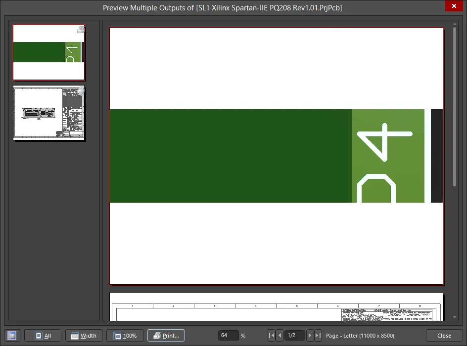
表示の操作、プリンター設定ダイアログへのアクセス、印刷、ページの Windows クリップボードへのコピー、アクティブページの Windows メタファイルとしてのエクスポートを行うためのコントロールが、レポートプレビューの下部および右クリックメニューに用意されています。
印刷
Print をクリックして、出力を指定した印刷デバイスへ直接送信します。あるいは、割り当てられた出力は次のいずれかの方法でも印刷できます。
-
F9 キーを押します。
-
右クリックして、コンテキストメニューから Print コマンドを選択します。
-
Tools » Print コマンドを使用します。
-
選択(フォーカス)されている出力について、Page Setupダイアログの Print ボタンをクリックします。これは、その特定の出力のページのみを印刷し、印刷ジョブに割り当てられたすべての出力の全ページを印刷するわけではない点に注意してください。
-
Print Previewダイアログの Print ボタンをクリックします。
-
Job Manager Toolbarツールバーの
 ボタンをクリックします。
Print コントロールと上記の最初の 3 つの方法は、直接印刷を提供します。上記の最後の 2 つの方法は、Printer Configurationダイアログを介した間接印刷です。
複数の印刷ジョブをまとめてバッチ印刷するプロセスはありません。プレビュー/印刷されるのは、現在選択されている印刷ジョブに割り当てられた出力のみです。すべての出力を印刷するには、定義されている各印刷ジョブを個別に選択して印刷してください。
Project Releaser から
PCB プロジェクトの構成に割り当てられた 1 つ以上の Output Job ファイルで定義された出力は、その構成がリリースされると生成されます。この生成は高完全性のリリースプロセスの一部として行われ、リリースデータはサーバー上のターゲット Item の新しい計画リビジョンに保存されます。これを実行するためのインターフェースが Project Releaser です。
Project Releaser には次の方法でアクセスできます。
-
メインメニューから Project » Project Releaser コマンドを選択します(対象プロジェクトのソースドキュメントをアクティブドキュメントとして開いている状態)。
-
Projects panel で対象プロジェクトのエントリを右クリックし、コンテキストメニューから Project Releaser コマンドを選択します。
notが Project Releaser の実行前に定義されていない場合でも、代わりにリリースプロセスの一部として実行できます。
リリースに Fabrication および Assembly のデータアイテムを含めるには、それらに少なくとも 1 つの OutputJob ファイルが割り当てられている必要があります。名前がサブストリング 'fab' および 'ass' で始まる Output Job ファイルがある場合、Release ビューに初めてアクセスしたときに、それらの OutJob はそれぞれ Fabrication Data および Assembly Data セクションへ自動的に割り当てられます。該当しない場合は、各ケースで適用する OutJob を手動で割り当てる必要があります。

選択した構成に対して生成される出力の例リスト。
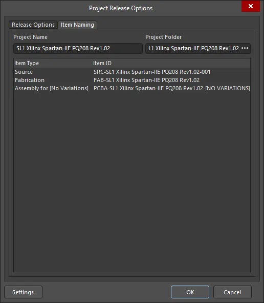
Project Releaser から、左下隅の Options ボタンをクリックして Project Release Options dialog を開きます。このダイアログは、適用する OutJob の割り当てと、プロジェクトをリリースする際にサーバー上のターゲットデータアイテム(生成データを受け取るリビジョン)の命名方法を定義するために使用します。Release Options タブには、必要な出力データを有効化するための複数のオプションが Output Jobs 領域に含まれています。

Project Release Options ダイアログの Release Options タブ。
現在プロジェクトに関連付けられた Output Job ファイルがない場合、Project Releaser がそれを検出し、デフォルトのものを追加するかどうかを尋ねられます。追加することを選択すると、次のものが作成されます。
-
Fabrication.OutJob - 次の出力が定義されたもの:
-
Documentation Outputs: PCB Prints
-
Fabrication Outputs: Gerber, NC Drill, and IPC-2581
-
Validation Outputs: Design Rules Check, Footprint Comparison Report
-
Export Outputs: Save As/Export PCB (in ASCII format)
-
Assembly.OutJob - 次の出力が定義されたもの:
-
Documentation Outputs: PCB 3D Print, Schematic Prints, Composite Drawing
-
Assembly Outputs: Pick and Place Report, Assembly Drawings, Test Point Report
-
Report Outputs: Bill of Materials, Component Cross Reference, GOST BOM
-
Export Outputs: Export STEP
プロジェクトに少なくとも 1 つの OutJob ファイルが定義されている場合、この自動作成は提示されません。
リリースプロセスの詳細については、Design Project Release ページをご覧ください。


 AI で翻訳