
Zmiana sposobu postrzegania przestrzeni projektowej
Gdy po raz pierwszy przeniesiesz płytki do edytora złożeń wielopłytkowych, są one schludnie ułożone w jednej płaszczyźnie – możesz to sobie wyobrazić tak, jakby wszystkie leżały obok siebie na wirtualnym stole. W ciągu kilku minut przesuniesz tę, obrócisz tamtą i przyciągniesz inną bliżej siebie! A potem obrócisz widok i nagle nie jesteś już nawet pewien, gdzie jest góra!
Praca w przestrzeni projektowej 3D wymaga umiejętności zarządzania widokiem tej przestrzeni oraz umiejętności manipulowania obiektami w tej przestrzeni. To dwie odrębne umiejętności: sterowanie widokiem przestrzeni i pozycjonowanie płytek w tej przestrzeni – zacznijmy od technik, których używasz do sterowania widokiem przestrzeni.
 ).
).Orientowanie widoku w przestrzeni projektowej
W lewym dolnym rogu przestrzeni projektowej edytora złożeń wielopłytkowych znajduje się czerwono-zielono-niebieski znacznik osi, nazywany design space gizmo.
 przestrzeni projektowej (kolorowych strzałek i płaszczyzn w lewym dolnym rogu przestrzeni projektowej), aby sterować widokiem przestrzeni projektowej.")
Użyj manipulatorów (gizmo) przestrzeni projektowej (kolorowych strzałek i płaszczyzn w lewym dolnym rogu przestrzeni projektowej), aby sterować widokiem przestrzeni projektowej.
Manipulator przestrzeni projektowej służy do zmiany orientacji widoku w przestrzeni projektowej.
Każdej osi przestrzeni projektowej oraz odpowiadającej jej płaszczyźnie przypisano kolor:
-
Blue – oś Z, widok w kierunku płaszczyzny XY. Możesz to traktować jako widok z góry lub z dołu.
-
Red – oś X, widok w kierunku płaszczyzny YZ. Możesz to traktować jako widok z przodu lub z tyłu.
-
Green – oś Y, widok w kierunku płaszczyzny XZ. Możesz to traktować jako widok z lewej lub z prawej strony.
Gdy najedziesz kursorem na kolorowy element manipulatora, stanie się jaśniejszy, co oznacza, że jest aktywny. Po kliknięciu danego koloru widok zostanie zorientowany tak, abyś patrzył down wzdłuż tej osi na złożenie. Drugie kliknięcie odwróci widok, patrząc wzdłuż tej samej osi z przeciwnego kierunku. Poniższa tabela podaje więcej szczegółów dotyczących różnych zachowań.
Skróty sterowania widokiem wyrównujące do osi przestrzeni projektowej
Te skróty wyrównują widok do osi przestrzeni projektowej:
| Skrót | Zachowanie |
|---|---|
Z klawisz lub kliknij Blue na manipulatorze przestrzeni projektowej |
Ponownie zorientuj widok tak, aby patrzeć wzdłuż osi Z, bezpośrednio na płaszczyznę XY. Kliknij Niebieski drugi raz, aby zobaczyć z przeciwnego kierunku lub użyj skrótu Shift+Z. |
X klawisz lub kliknij Red na manipulatorze przestrzeni projektowej |
Ponownie zorientuj widok tak, aby patrzeć wzdłuż osi X, bezpośrednio na płaszczyznę YZ. Kliknij Czerwony drugi raz, aby zobaczyć z przeciwnego kierunku lub użyj skrótu Shift+X. |
Y klawisz lub kliknij Green na manipulatorze przestrzeni projektowej |
Ponownie zorientuj widok tak, aby patrzeć wzdłuż osi Y, bezpośrednio na płaszczyznę XZ. Kliknij Zielony drugi raz, aby zobaczyć z przeciwnego kierunku lub użyj skrótu Shift+Y. |
Użyj manipulatora przestrzeni projektowej, aby zmienić orientację widoku.
Skróty sterowania widokiem wyrównujące do bieżącego widoku
Wiele ruchów widoku, które możesz wykonać, nie odnosi się do osi przestrzeni projektowej, lecz do bieżącego widoku. Bieżący widok jest określany jako bieżąca płaszczyzna widoku – to płaszczyzna, którą aktualnie widzisz, patrząc w monitor. Na przykład podczas przybliżania zawartość przestrzeni projektowej jest przyciągana bliżej, niezależnie od aktualnego kąta osi przestrzeni projektowej.
Te skróty są względne względem bieżącej płaszczyzny widoku:
| Skrót | Zachowanie |
|---|---|
Ctrl+Mouse Wheel |
Przybliż/oddal |
Right-Click, Hold&Drag |
Wyświetla kursor dłoni do przesuwania, gdy przesuwasz widok przestrzeni projektowej w bieżącej płaszczyźnie widoku. |
Shift+Right-Click, Hold&Drag |
Obróć widok przestrzeni projektowej wokół bieżących poziomej i pionowej osi płaszczyzny widoku. Miejsce kliknięcia i przeciągnięcia definiuje środek obrotu. |
Ctrl+PgDn |
Dopasuj powiększenie tak, aby objąć wszystkie obiekty, w tym znacznik początku układu współrzędnych. |
Bieżący widok można zmieniać za pomocą skrótów myszy i klawiatury.
Zmiana typu projekcji
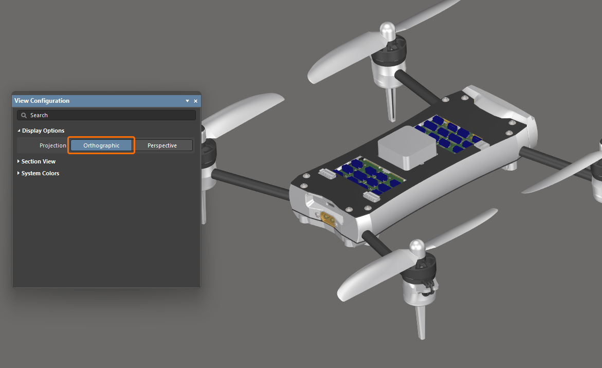
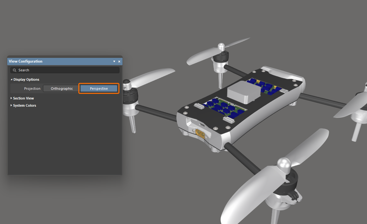
Możesz przełączyć widok edytora złożeń wielopłytkowych na perspektywiczny lub ortograficzny, przełączając polecenie View » Toggle Projection Type w menu głównym (skrót: P) albo używając opcji Projection w obszarze Display Options panelu View Configuration.
-
Perspektywa to widok obrazu trójwymiarowego, który przedstawia wysokość, szerokość i głębię, zapewniając bardziej realistyczny obraz lub grafikę.
-
Ortograficzny to widok obiektów trójwymiarowych, które są tworzone przez rzutowanie widoku obiektu na płaszczyznę, zwykle ustawioną równolegle do jednej z płaszczyzn obiektu. Wybierz tę opcję, aby zobaczyć dokładne położenie obiektów i tekstu w złożeniu wielopłytkowym bez zasłaniania przez otaczające obiekty.
|
Projection złożenia wielopłytkowego jest ustawione na Orthographic. Projection tego samego złożenia wielopłytkowego jest ustawione na Perspective. |
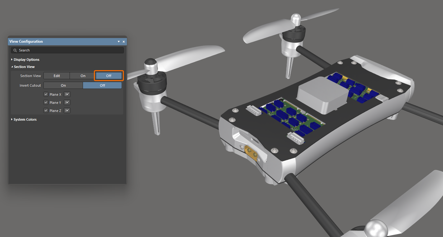
Definiowanie widoku przekroju złożenia
Widok przekroju to taki, który może służyć do ujawnienia szczegółów wewnątrz złożenia, które normalnie mogłyby nie być widoczne. Osiąga się to przez zdefiniowanie płaszczyzn, w których część złożenia jest sliced lub cut away. Edytor złożeń wielopłytkowych obsługuje definiowanie płaszczyzny przekroju wzdłuż każdej z trzech osi, co pozwala definiować przekrój w 1, 2 lub 3 kierunkach.
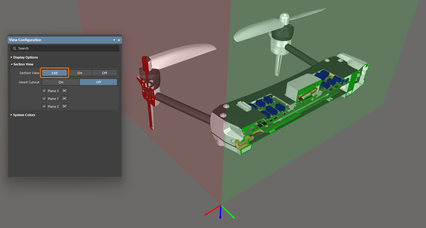
Widok przekroju może być w trybie Off, On lub Edit. W trybie Edit wyświetlane są płaszczyzny przekroju; każda płaszczyzna jest wskazywana przez kolorową półprzezroczystą powierzchnię rozchodzącą się od początku widoku przekroju. Początek widoku przekroju jest definiowany przez trzy kolorowe strzałki, nazywane section view gizmo. Możesz włączyć ich wyświetlanie i skonfigurować ich kierunek w panelu View Configuration w obszarze Section View.
|
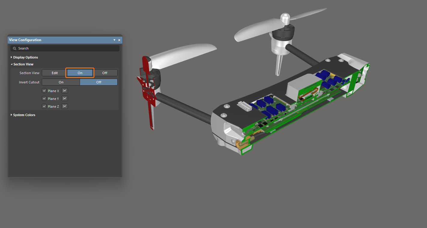
Włącz tryb Edit, aby zastosować przekrój oraz aby płaszczyzny były widoczne i edytowalne. Włącz tryb On, aby zastosować przekrój, a płaszczyzny ukryć. Włącz tryb Off, aby ukryć panele i uzyskać wyraźniejszy widok złożenia wielopłytkowego. |
Aby pracować z widokiem przekroju:
-
Przełącz wyświetlanie Section View między Edit/On/Off, wybierając View » Toggle Section View z menu głównego (skrót:
Shift+Ctrl+V). -
W trybie Edit położenie każdej płaszczyzny przekroju można zmienić, klikając i przeciągając odpowiednią kolorową strzałkę manipulatora widoku przekroju.
-
Widok przekroju jest sterowany manipulatorem widoku przekroju, który kontroluje położenie płaszczyzn przekroju X, Y i Z. Położenie manipulatora definiuje początek widoku przekroju.
-
Domyślnie ukrywane jest wszystko, co znajduje się w ujemnej przestrzeni bieżącego widoku przekroju, tzn. wyświetlane są tylko obiekty znajdujące się w dodatniej przestrzeni widoku przekroju. To zachowanie zostaje odwrócone, jeśli w panelu View Configuration włączona jest opcja Invert Cutout. Wtedy obiekty w przestrzeni ujemnej są wyświetlane, a obiekty w przestrzeni dodatniej są ukrywane.
-
W trybie Edit można włączyć/wyłączyć określoną płaszczyznę przekroju za pomocą pól wyboru Plane X / Plane Y / Plane Z (można wyłączyć jedną lub dwie płaszczyzny), a kierunek zastosowania przekroju dla każdej płaszczyzny można przełączać przy użyciu odpowiedniego elementu sterującego
 . Ustawienia zostaną zachowane podczas przełączania do trybu On widoku przekroju.
Konfigurowanie kolorów systemowych
Użyj obszaru System Colors w panelu View Configuration, aby skonfigurować kolory elementów systemowych, takich jak zaznaczone obiekty, tło przestrzeni projektu itp. Kliknij próbkę koloru, aby wybrać wymagany kolor dla odpowiadającego elementu.

 Tłumaczenie SI