
Работа с классами на схеме и PCB
Класс — это именованная группа объектов. Помимо того, что классы помогают проектировщику выбирать интересующие объекты при просмотре проекта, их также можно использовать для применения требований к проектированию ко всем объектам в этой группе, то есть в классе.
Классы могут генерироваться на основе структурных аспектов проекта, например: цепи или компоненты на одном листе, либо цепи в одной шине. К таким структурным, автоматически создаваемым программой классам относятся: Component, Net, Design Channel и Structure.
Также можно создавать пользовательские классы: либо через Constraint Manager, если вам так удобнее задавать требования к проектированию, либо с помощью параметров схемы и классов PCB, если вы предпочитаете подход на основе правил проектирования.

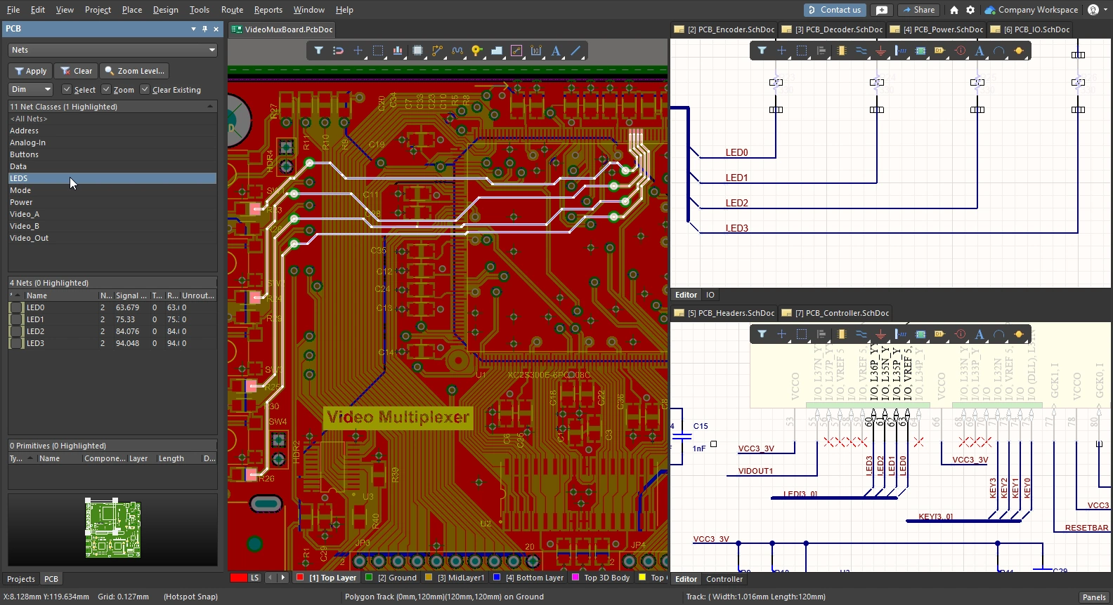
Классы — отличный способ управлять логическими группами компонентов и цепей; здесь требования к трассировке применяются к классу LEDS в Constraint Manager.
Поддерживаемые классы и где они задаются
Поддержка определения классов изначально была введена в редакторе PCB через Object Class Explorer. После этого добавили поддержку определения наиболее часто используемых классов в редакторе схем — то есть компонентов и цепей. Компоненты можно добавлять в класс, добавив к компоненту параметр ClassName, а цепи — присоединив директиву набора параметров, содержащую параметр Net Class Name. Эти определения классов обнаруживаются и переносятся в PCB при синхронизации проекта.
Появление Constraint Manager обеспечило более простой и структурированный подход к заданию требований, таких как классы, наряду с другими физическими и электрическими требованиями проекта. Ограничения — это настройки уровня проекта; их можно редактировать в любое время как из редактора схем, так и из редактора PCB, но синхронизировать всё равно нужно через систему ECO.
Если одновременно присутствуют и параметрические определения классов цепей, и классы цепей в Constraint Manager, то параметрические определения не применяются. Таблица в сворачиваемом разделе ниже содержит сведения обо всех поддерживаемых типах классов и о том, где их можно задавать.
Available Class Types
| Class Type | Software-created based on structure |
Schematic Editor parameters |
PCB Editor Object Class Explorer |
|
| Net | ✓ |
🗸 |
✓ | ✓ |
| Component | ✓ |
🗸 |
✗ | ✓ |
| Layer | ✗ | ✗ | ✗ | ✓ |
| Pad | ✗ | ✗ | ✗ | ✓ |
| From-to | ✗ | ✗ | ✗ | ✓ |
| Differential Pair | ✗ | ✗ |
✓ | ✓ |
| xNet | ✗ | ✗ | ✓ | ✗ |
| xSignal | ✗ | ✗ | ✓ | ✓ |
| Design Channel | ✓ |
✗ | ✗ | ✓ |
| Polygon | ✗ | ✗ | ✗ | ✓ |
| Structure | ✓ |
✗ | ✗ | ✓ |
Определение классов с помощью параметров схемы
Вы можете создавать пользовательские классы компонентов и классы цепей, добавляя или присоединяя параметр к соответствующему компоненту или цепи. Затем будут созданы классы компонентов и цепей PCB, если включены соответствующие флажки User-Defined Classes на вкладке Class Generation диалогового окна Options for Project. Подробнее см. configuring these options.
Пользовательский класс компонентов
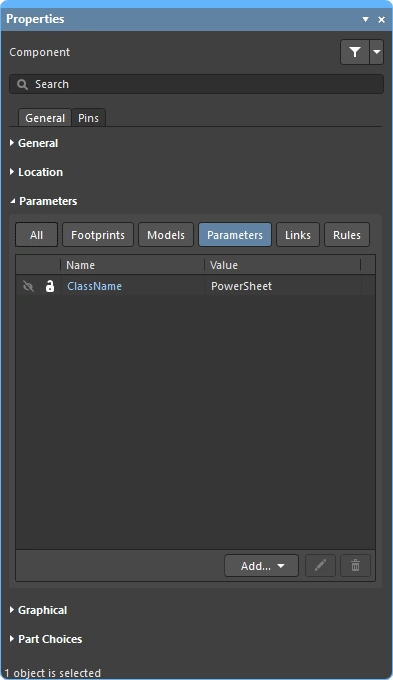
Чтобы добавить компоненты в класс компонентов, добавьте к компоненту параметр, у которого строка параметра Name установлена в ClassName, а строка параметра Value — в имя класса. Параметр нужно добавить к каждому компоненту, который вы хотите включить в класс. Это можно сделать одним действием редактирования: сначала выделите все компоненты, затем добавьте параметр на панели Properties. Либо, если компоненты расположены рядом, можно использовать директиву Blanket с присоединённой директивой Parameter Set.
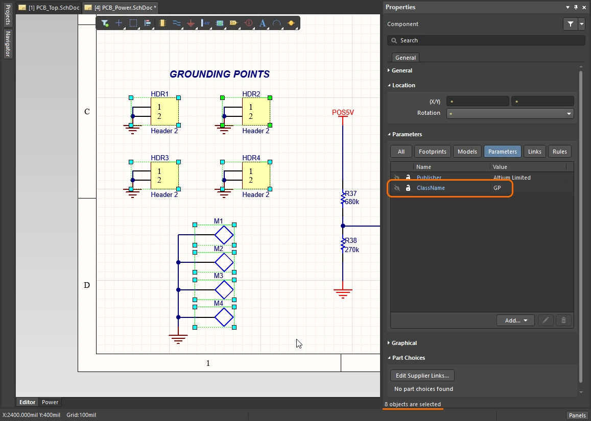
![]()
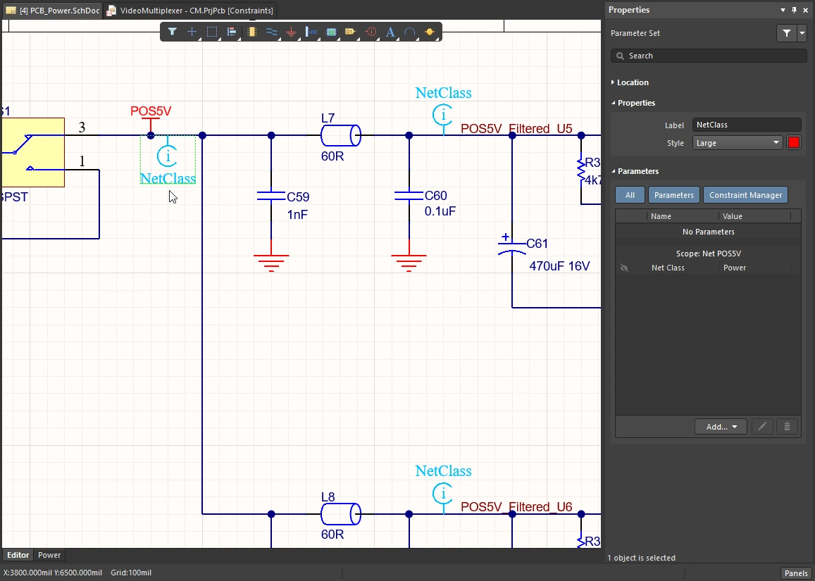
Пользовательский класс цепей
Чтобы параметрически добавить цепь (или цепи в шине либо сигнальном жгуте) в класс цепей PCB, нужно присоединить параметр к этой цепи/шине/жгуту. Параметры к цепи можно присоединять, разместив директиву Parameter Set так, чтобы её конец касался цепи/шины/жгута, а затем добавив в эту директиву параметр Net Class Name.
Эту директиву Parameter Set можно копировать и вставлять в разные места на схеме, чтобы добавить несколько отдельных цепей в один и тот же класс цепей PCB. В качестве альтернативы можно использовать директиву Blanket.
![]()
Использование Blanket для применения директивы к нескольким цепям
Вы также можете добавить несколько цепей в класс цепей PCB, разместив директиву Blanket, которая накрывает все эти цепи. Назначение Blanket — позволить применить директиву ко всем цепям под «покрывалом» (либо определяемым по идентификатору цепи, например Net Label или Power Port, находящимся под Blanket, либо цепи, у которой хотя бы одна конечная вершина находится внутри Blanket).
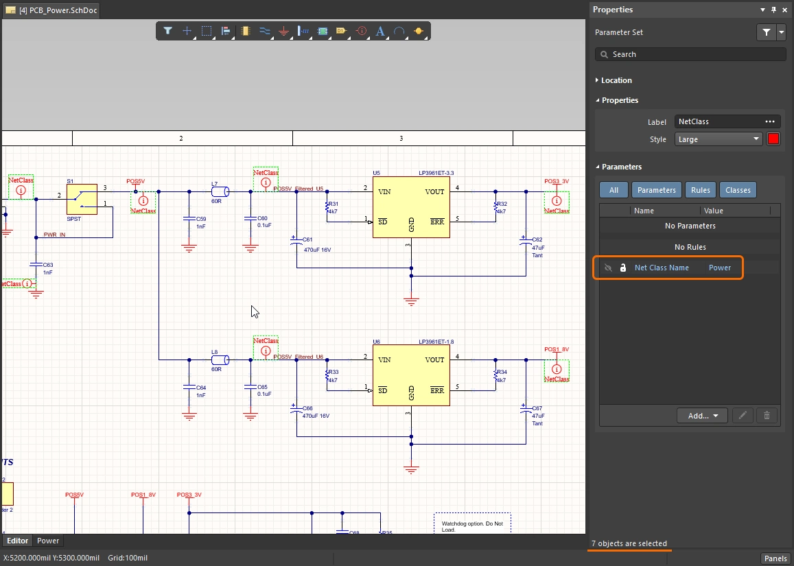
Вместо того чтобы размещать директиву Parameter Set так, чтобы она касалась проводника, разместите её так, чтобы она касалась края Blanket, как показано на изображении ниже. Обратите внимание: имя класса цепей PCB задаётся значением Parameter внутри объекта Parameter Set, а не отображаемым именем объекта Parameter Set. В примере ниже Parameter Set также используется для задания правила проектирования ширины трассировки.

Использование директивы Blanket для объединения всех цепей под ней в класс цепей PCB с именем Power. Обратите внимание: имя директивы Parameter Set не используется для именования класса — это только визуальная подсказка.
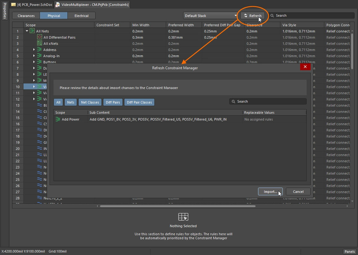
Определение классов в Project Constraint Manager
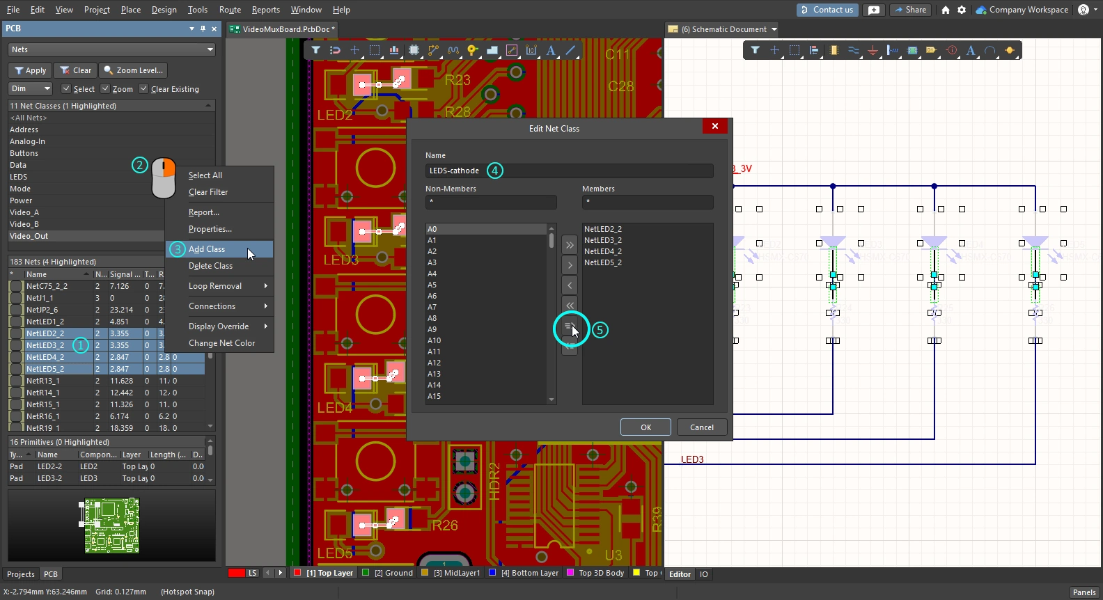
Классы — ключевая возможность при работе с Constraint Manager, позволяющая легко применять и настраивать проектные ограничения сразу для множества цепей. В Constraint Manager классы добавляются, редактируются и удаляются командами контекстного меню (по правому клику), как показано в видео ниже. Цепи можно добавлять по одной или выделять несколько стандартными приёмами Windows, а затем добавлять их в класс.
Constraint Manager Object Class Explorer можно использовать для просмотра и редактирования всех классов в рамках проекта. Все классы, определённые в Constraint Manager, переносятся в PCB при синхронизации проекта независимо от настроек опций на вкладке Class Generation диалогового окна Options for Project.
Простая демонстрация создания класса цепей в Constraint Manager.
Подробнее см. Constraint Manager.
Классы, генерируемые при переносе проекта
Создание автоматически генерируемых классов, а также классов, получаемых из параметров схемы, настраивается на вкладке Class Generation диалогового окна Options for Project.
-
Automatically generated classes - получаемые из структуры проекта; могут включать шины/жгуты (классы цепей), содержимое листа (классы компонентов) и структуру проекта (классы структуры). Эти классы генерируются при переносе проекта со схемы в PCB и доступны независимо от выбранного подхода управления проектными ограничениями (Constraint Manager или Design Rules). Они недоступны в редакторе схем во время ввода схемы — например, при просмотре на панели Navigator.
-
User-defined classes - получаемые из параметров проекта, добавленных к компоненту или цепи. Обратите внимание: классы, определённые в Constraint Manager, не управляются этими опциями.
Генерация этих классов настраивается на вкладке Class Generation tab диалогового окна Options for Project. Обратите внимание: какие классы в итоге синхронизируются с PCB, определяется опциями на вкладке Comparator; убедитесь, что они настроены должным образом.

Используйте опции на вкладке Class Generation, чтобы настроить генерацию производных классов и пользовательских классов при синхронизации проекта.
Automatically Generated Classes
| Generate Net Classes for Buses | Автоматически создавать класс цепей для каждой именованной шины в проекте. Членами класса будут цепи, входящие в эту шину. |
| Generate Net Classes for Components | Автоматически создавать класс цепей для каждого компонента в проекте. Членами класса будут цепи, подключенные к выводам этого компонента. Класс цепей будет именоваться по обозначению компонента в формате <ComponentDesignator>_Nets. |
| Generate Separate Net Classes for Bus Sections | Автоматически создавать отдельный класс цепей для каждого участка шины. Участок шины создается, когда задается шина, которая фактически является частью более крупной шины, например, A[2..0] из шины A[15..0]. |
| Generate Net Classes for Named Signal Harnesses | Автоматически создавать класс цепей для каждого именованного жгута сигналов (signal harness) в проекте. Членами класса будут цепи, связанные с сигналами, собранными этим именованным жгутом сигналов. Именованный жгут сигналов имеет присоединенную к нему метку цепи; сгенерированному классу цепей присваивается это имя. |
| Schematic Sheet | Секция сетки (grid) в диалоге перечисляет все листы в проекте. Для каждого листа можно выборочно генерировать: класс компонентов, PCB-комнату (room), класс цепей и класс структуры. |
| Sheet Name/Full Path | Имя и расположение листа схемы. |
| Component Classes | Столбец флажков. Если включено, создается класс компонентов, содержащий все компоненты на этом листе (с именем, совпадающим с именем символа листа). |
| Generate Rooms | Столбец флажков. Если включено, для этого листа схемы автоматически создается комната (доступно только если включен флажок Component Class). PCB-комнате назначается соответствующий класс компонентов. При начальной синхронизации проекта комнаты размещаются в левом нижнем углу платы. Подробнее см. Working with Rooms. |
| Net Classes Scope | Эти параметры определяют, будет ли сгенерирован класс цепей для данного листа схемы (класс именуется так же, как имя символа листа).
|
| Structure Classes | Включите, чтобы генерировать класс структуры. Членами класса структуры являются включенные класс компонентов и класс цепей. Отредактируйте Structure Class в PCB-редакторе, чтобы добавить другие классы цепей/компонентов/структур. Используйте режим Structure панели PCB, чтобы находить компоненты и цепи в этом классе структуры. |
User-Defined Classes
| Generate Component Classes | Включите, чтобы генерировать пользовательские классы компонентов. Чтобы добавить компонент в пользовательский класс компонентов, добавьте компоненту параметр |
| Generate Rooms for Component Classes | Включите этот параметр, чтобы генерировать PCB-комнату размещения для каждого сгенерированного пользовательского класса компонентов и назначать этот класс компонентов комнате. Комната размещения имеет то же имя, что и класс компонентов. |
| Generate Net Classes | Включите, чтобы генерировать пользовательские классы цепей. Параметры добавляются к цепи путем присоединения к ней объекта parameter set , а затем добавления параметра Если проект использует Constraint Manager, классы цепей не создаются из объектов набора параметров. |
 ).
). ).
). ).
). ).
). ).
).Создание классов в PCB-редакторе
PCB-редактор Altium Designer изначально создавался как редактор, ориентированный на правила проектирования: требования к плате задавались в диалоге PCB Rules and Constraint Editor (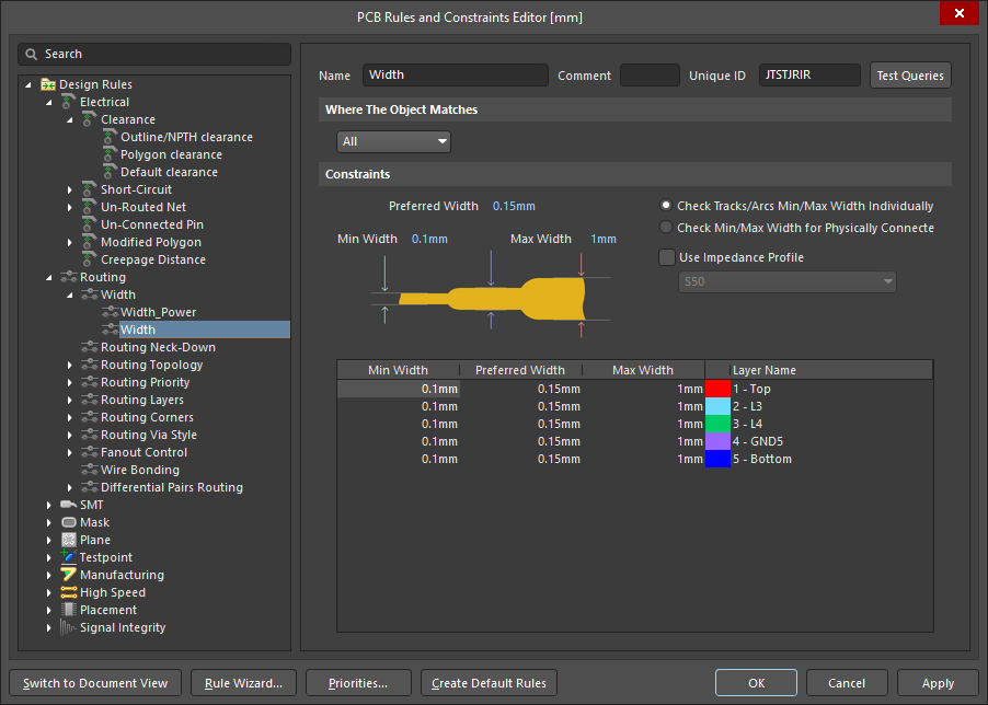 ), а классы проекта определялись в PCB-редакторе Object Class Explorer (
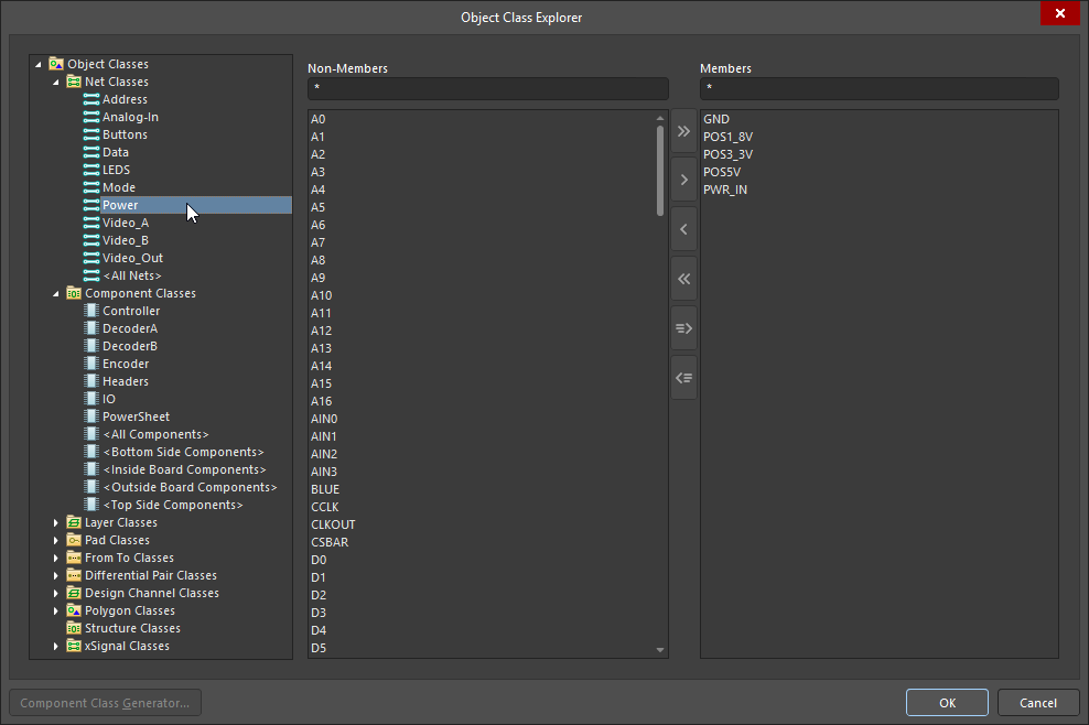 ). Это подход по умолчанию для нового проекта.
Если при создании проекта включена опция Constraint Management, то требования настраиваются в Constraint Manager () вместо диалога PCB Rules and Constraint Editor. В этой ситуации полный набор классов по-прежнему можно определять и редактировать в PCB-редакторе Object Class Explorer, а подмножество типов классов, которые можно синхронизировать между схемой и PCB, также редактируется в Object Class Explorer (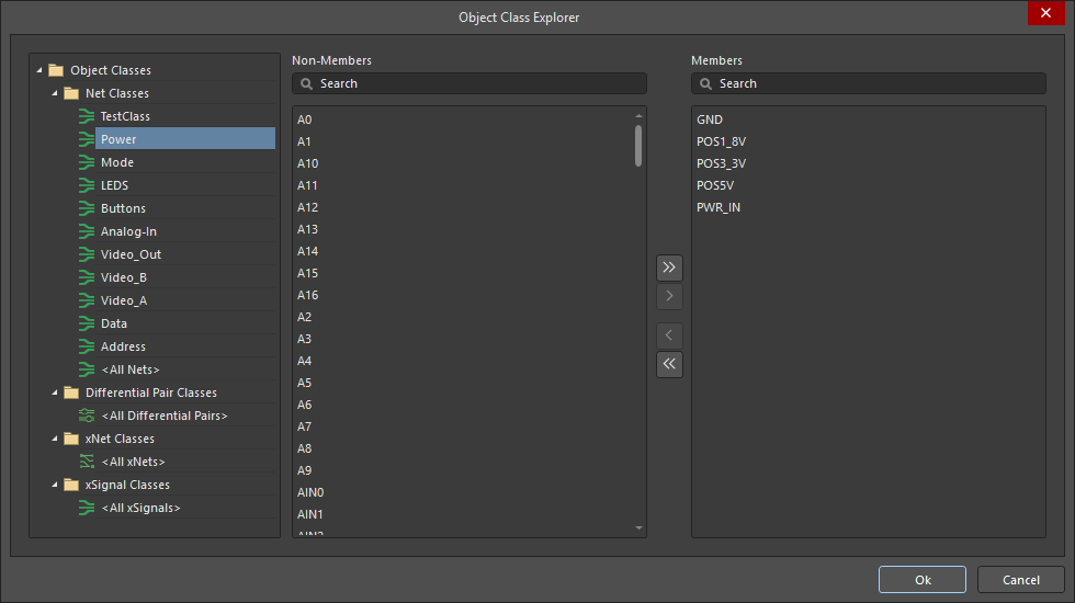 ) Constraint Manager.
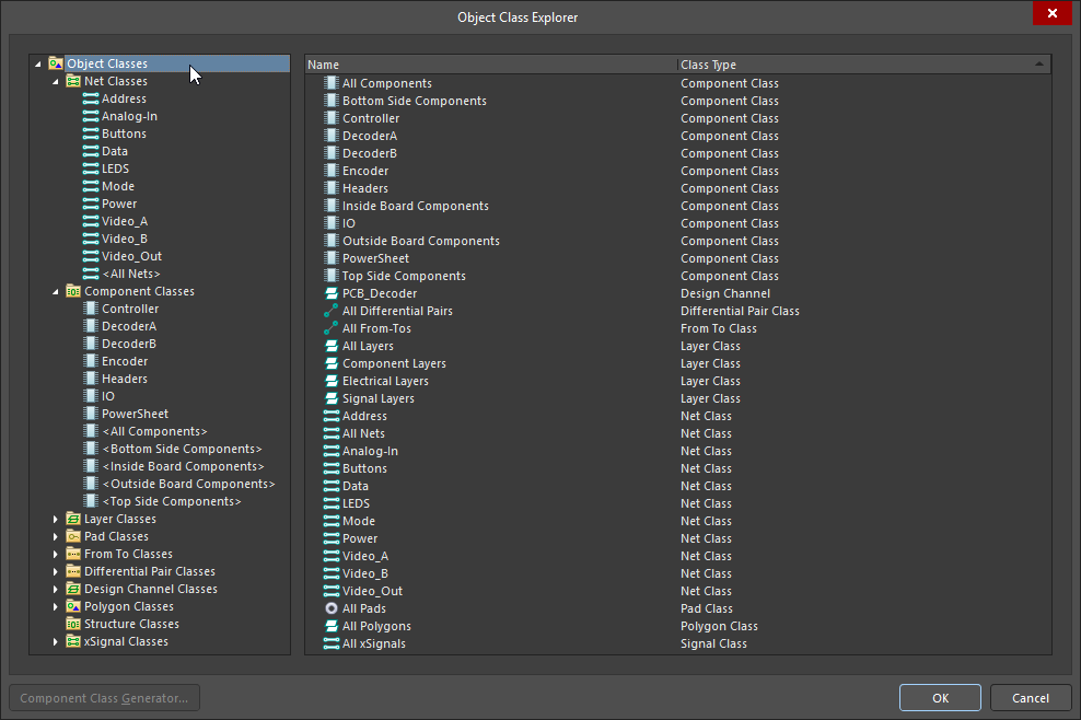
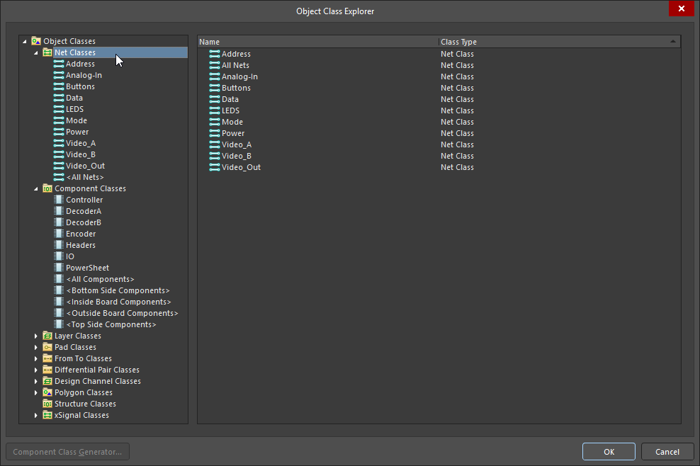
PCB Object Class Explorer
Классы можно добавлять, редактировать и удалять в Object Class Explorer.
-
Чтобы получить доступ и редактировать полный набор классов, доступных в PCB-редакторе, выберите Design » Classes в меню PCB-редактора, чтобы открыть Object Class Explorer.
-
Constraint Manager Object Class Explorer также можно использовать для редактирования классов, которые синхронизируются между схемой и PCB. Чтобы открыть его, щелкните правой кнопкой мыши в Constraint Manager и выберите Classes » Class Explorer в контекстном меню.
Object Class Explorer (PCB editor)
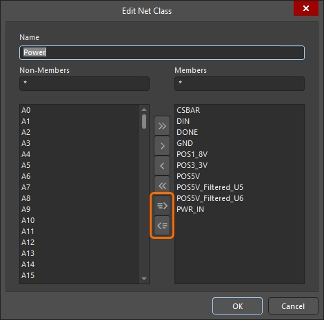
| Class Types and Classes | Древовидная структура в левой панели диалога используется для просмотра всех классов объектов, доступных на PCB. Нажмите значок Object Classes в верхней части дерева, чтобы отобразить список всех классов, определенных в проекте ( |
| Non-Members | Когда в дереве слева выбран конкретный класс, в центральном столбце отображается список всех объектов, которые в данный момент не являются членами выбранного класса. Выберите объекты, не входящие в класс, которые нужно добавить в текущий класс (используя стандартные приемы выделения Windows), затем используйте элементы управления между панелями Non-Member и Member, чтобы добавить выбранные объекты в этот класс (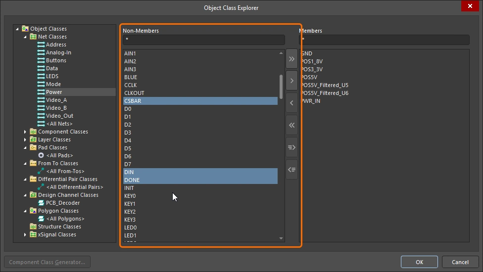 ). ). |
| Members | Когда в дереве слева выбран конкретный класс, в правом столбце отображается список всех объектов, которые в данный момент являются членами выбранного класса. Выберите членов класса, которые нужно удалить (используя стандартные приемы выделения Windows), затем используйте элементы управления между панелями Non-Member и Member, чтобы удалить выбранные объекты из этого класса (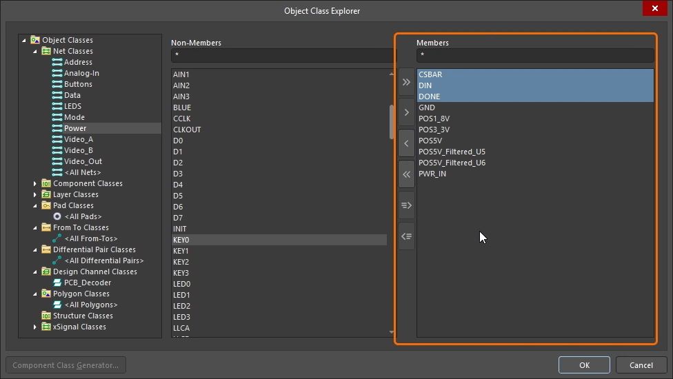 ). ). |
| |
Добавить все объекты из Non-Members в список Members. |
| |
Добавить выбранные объекты из Non-Members в список Members. |
| |
Удалить выбранные объекты из Members. |
| |
Удалить все объекты из Members. |
| |
Добавить в список Members объекты, которые в данный момент выделены в рабочей области. Этот элемент управления доступен только тогда, когда возможно предварительно выделить объект(ы) в рабочей области. |
| |
Удалить из списка объекты, которые в данный момент выделены в рабочей области. Этот элемент управления доступен только тогда, когда возможно предварительно выделить объект(ы) в рабочей области. |
| |
Кнопка Component Class Generator доступна только при создании/редактировании класса компонентов. Нажатие открывает диалог Component Class Generator, который можно использовать для быстрого формирования состава класса компонентов на основе заданных критериев поиска. |
 )
) )
) )
) )
)Выбор между редакторами
Ключевая возможность для работы между различными редакторами — это Cross Select Mode: каждый компонент или цепь (net), выбранные в одном редакторе, также выбираются и в других редакторах. Cross Select Mode включается через меню Tools в любом редакторе, который это поддерживает (или нажатием сочетания клавиш Shift+Ctrl+X). Когда вы щёлкаете по компоненту или объекту цепи в одном редакторе, этот объект автоматически выбирается в других открытых редакторах.
Чтобы работать с логическими соединениями на схеме (цепи, соединённые метками цепей, портами и т. п.), удерживайте Alt и щёлкайте для выбора по цепи в редакторе схем. Это выберет всю цепь/шину/жгут на каждом листе проекта, выполняя масштабирование так, чтобы показать выбранные объекты цепи. То, как результаты визуально отображаются на целевых страницах, определяется параметрами Cross Select Mode и Highlight Methods на странице System – Navigation page диалога Preferences dialog (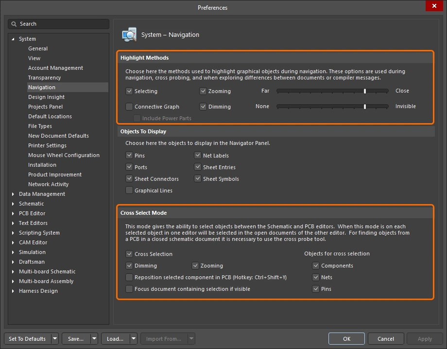 ).
).
Включите режим Cross Select, чтобы перемещаться между редакторами.
Работа с классами в PCB Editor
Классы — это логические группы, определяемые разработчиком, и поэтому они являются отличным инструментом, помогающим структурировать, анализировать и проверять проект.
Просмотр классов
Панель PCB поддерживает просмотр PCB в самых разных режимах, например по цепям (Nets) или компонентам (Components), а для тех режимов, где это поддерживается, также можно просматривать по классам этих объектов. Режимы, поддерживающие просмотр по классам, включают: компоненты, цепи, дифференциальные пары, xSignals, полигоны, а также структурные классы.
После выбора режима просмотра в верхней части панели, в верхнем разделе панели будет показан список всех доступных классов, как в примерах ниже. Если включён режим cross-select, то соответствующие объекты (где применимо) будут также выбраны и на листах схем.
Создание класса из выбранных объектов
Вы можете создать класс из набора объектов, выбранных в данный момент в PCB editor, включая: цепи (nets), компоненты и полигоны.
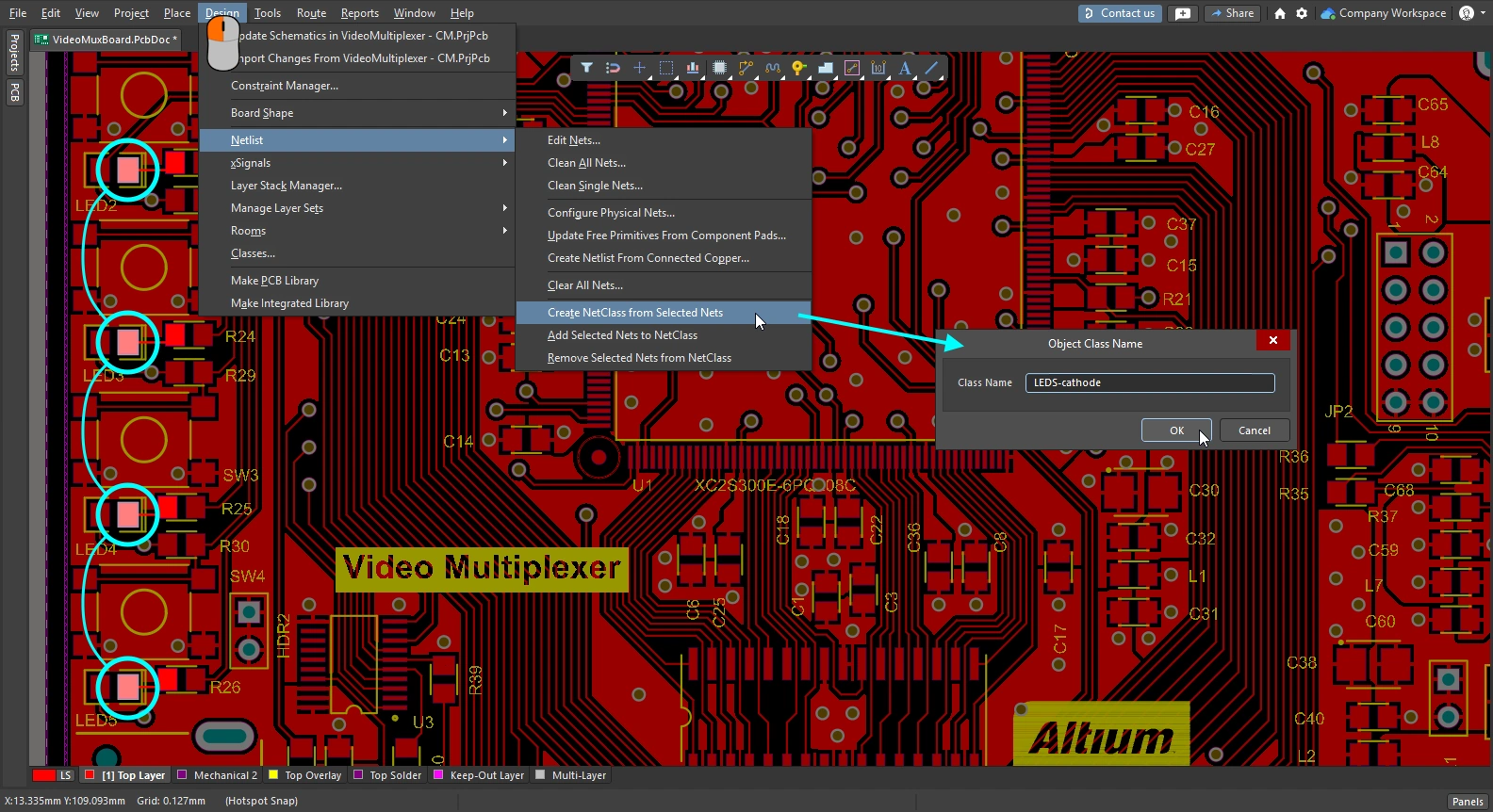
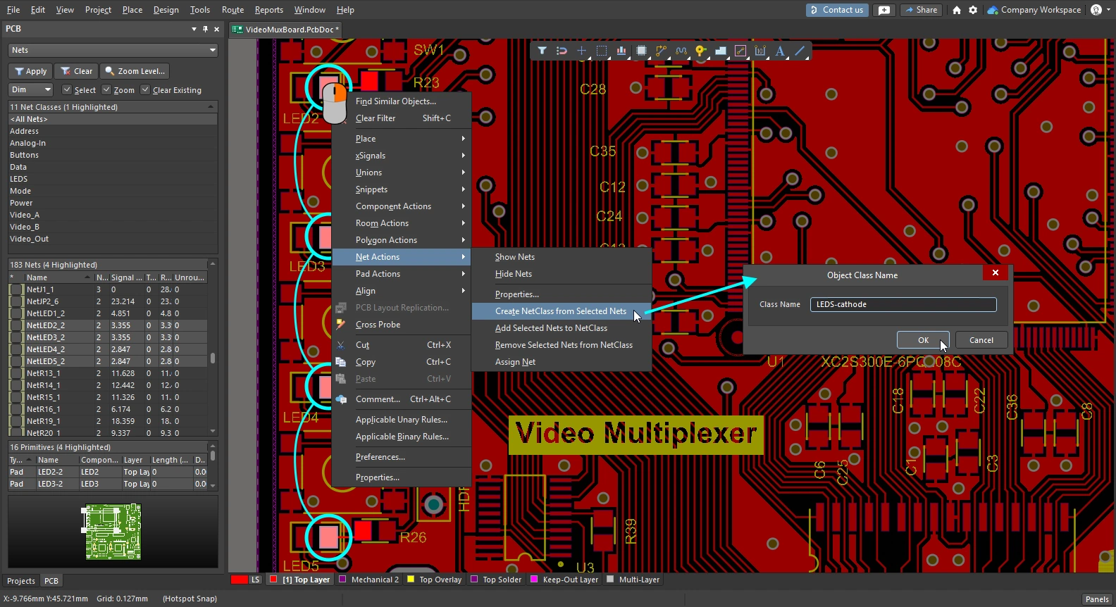
| Net class | Выберите как минимум один объект в каждой цепи в пространстве проектирования или выберите цепи в панели PCB. Затем выполните команду Create NetClass from Selected Nets из подменю Design » Netlist главного меню ( |
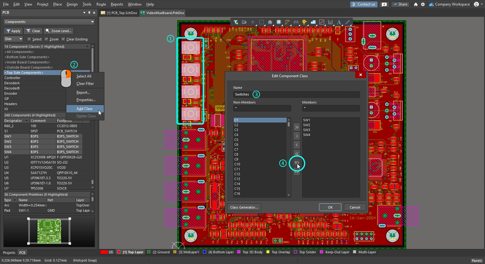
| Component class | Выберите компоненты в пространстве проектирования или на панели PCB. Затем щёлкните правой кнопкой в области Classes панели, чтобы получить доступ к команде Add Class, как показано на слайдах выше. Либо выберите команду Design » Classes, чтобы открыть Object Class Explorer, где можно создать новый класс и добавить в него выбранные компоненты. |
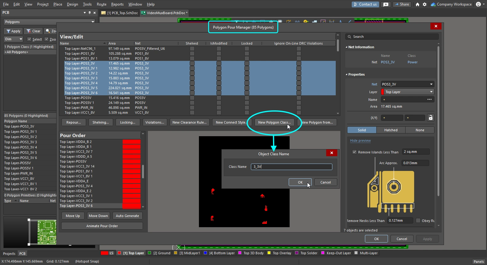
| Polygon class | Выберите нужные записи полигонов в диалоге Polygon Manager dialog, затем нажмите кнопку New Polygon Class . Задайте имя нового класса полигонов в диалоге Object Class Name dialog. |
 )
) ).
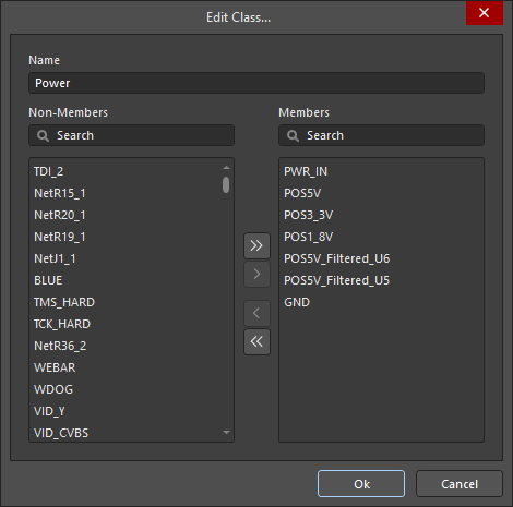
).Генератор классов компонентов
Ещё один способ создать класс компонентов — использовать Component Class Generator. Кнопка запуска генератора доступна в PCB Object Class Explorer и в диалоге Edit Component Class dialog.
Выполните команду Design » Classes, чтобы открыть PCB Object Class Explorer , щёлкните правой кнопкой по списку Component Classes слева и выберите команду New Class. Выберите новый класс в списке, затем нажмите кнопку Component Class Generator, чтобы открыть Component Class Generator. Либо щёлкните правой кнопкой в области Classes панели PCB (режим Components) и выберите Add Class. Задайте имя нового класса в диалоге Edit Component Class, затем нажмите кнопку Class Generator, чтобы открыть Component Class Generator.
 Используйте Component Class Generator, чтобы быстро сформировать список компонентов для включения в класс.
Component Class Generator Dialog
| Search/Filter Criteria | Поля слева в диалоге совместно задают критерии поиска/фильтрации, используемые для выбора компонентов, которые будут добавлены в качестве членов класса компонентов. Поля Designator, Comment и Footprint содержат предварительно заполненный список, либо вы можете ввести значение вручную (поддерживаются подстановочные знаки). Остальные поля содержат список доступных вариантов — выберите Any, чтобы исключить поле из процесса отбора. |
| Add Matching | Нажмите, чтобы добавить все компоненты, соответствующие заданным критериям поиска/фильтрации, в область Class Membership. |
| Clear Selected | Нажмите, чтобы удалить из класса все компоненты, которые сейчас выбраны в области Class Membership. |
| Class Name | Поле в правой верхней части диалога показывает текущее имя класса. При необходимости отредактируйте это поле. |
| Class Membership | Область ниже Class Name — это Class Membership, в которой перечислены все компоненты (по обозначению), выбранные для включения в класс компонентов. Компоненты в списке членства класса можно выбирать стандартными способами множественного выбора: Ctrl+click, Shift+click и Click+drag. |
Работа со структурными классами
Altium Designer поддерживает автоматическое создание классов цепей и компонентов при переносе проекта из Schematic в PCB. Помимо этого, он также позволяет определять иерархическую структуру классов. По сути, это даёт возможность группировать на уровне листа классы компонентов и/или цепей в родительский класс, сформированный на основе этого листа. Этот класс может быть дочерним по отношению к родительскому классу уровнем выше — и так вплоть до верхнего листа в вашем проекте.
Каждый из таких сгенерированных родительских классов называется Structure Class. Структурные классы воспроизводят структуру документов схемы в домене PCB, что идеально подходит для расширенной навигации. Их также можно использовать в логических запросах, например при задании области действия правил проектирования или при фильтрации объектов в пространстве проектирования PCB.
Концепция структурного класса
Структурный класс — это особый тип класса, который может содержать в качестве своих членов любой тип классов, включая: классы цепей, классы компонентов, классы слоёв, классы площадок, классы from-to, классы дифференциальных пар, классы design channel, классы полигонов и другие структурные классы. Автоматически создавая структурный класс для каждого листа схемы в проекте — содержащего компоненты и/или цепи — при переносе проекта в PCB, можно достоверно представить структуру проекта на стороне PCB.
 Иерархию проекта можно представить с помощью структурных классов: каждый класс соответствует одному листу схемы, с автоматически созданными подклассами, содержащими компоненты и/или цепи.
Структурные классы отражают иерархический проект, созданный листами схем. Что касается классов компонентов и цепей внутри каждого структурного класса, состав членов зависит от options specified при генерации Component и Net Classes из исходных листов схем.
Автоматическая генерация структурных классов
Автоматическая генерация структурных классов из листов схем проекта настраивается на вкладке Class Generation диалога Options for Project dialog (Project » Project Options). Чтобы сгенерировать структурный класс из исходного листа схемы в проекте, включите соответствующий флажок Generate в столбце Structure Classes. Если для этого листа схемы также включены флажок Component Class и параметры Net Class Scope, они станут членами этого структурного класса.

Укажите, для каких листов схем нужно генерировать структурный класс, и должны ли включаться компоненты и цепи этого листа.
 )
) ).
).Ручное определение классов структуры
Как и другие типы классов в документе PCB, вы можете создавать и управлять классами структуры вручную в редакторе PCB. Это можно сделать на панели PCB, просматривая иерархию структуры классов, либо в диалоге Object Class Explorer (Design » Classes). В этом диалоге классы структуры определяются в папке Structure Classes, а в контекстном меню (по правому щелчку) доступны привычные команды для добавления, переименования или удаления классов по мере необходимости. Классы структуры могут включать любые типы классов, поддерживаемые для использования в PCB-проекте.

Создавайте и управляйте своими классами структуры так же, как и любыми другими типами классов в редакторе PCB, в диалоге Object Class Explorer.
Просмотр иерархии структуры классов
В режиме панели PCB Structure Classes три основные области включают:
-
Список всех Structure Classes, определённых в данный момент для документа PCB; как автоматически сгенерированных из листов схемы, так и определённых в самом PCB.
-
Все Classes, которые являются определёнными членами выбранного класса структуры.
-
Отдельные Class Members внутри выбранного класса (компоненты, цепи и т. п.).

Установите режим панели PCB в Structure Classes, чтобы просматривать общую иерархию классов для документа PCB.
Режим Structure Classes |
|
| Structure Classes region | Верхняя область панели перечисляет все классы структуры, определённые в данный момент для документа PCB. Сюда входят классы, автоматически сгенерированные из исходных документов схемы проекта PCB (обозначаются значком |
| Classes region | Средняя область панели перечисляет всех членов классов для класса(ов) структуры, выбранного(ых) в области выше. Одинарный щелчок — для масштабирования и фильтрации отображения, двойной щелчок — для редактирования класса-участника. |
| Class Members | Нижняя область панели перечисляет всех членов класса(ов), выбранного(ых) в области выше. Одинарный щелчок — чтобы приблизить к элементу, двойной щелчок — чтобы редактировать свойства этого элемента. |
Использование классов структуры в логических запросах
Логические запросы — базовый подход, применяемый для нацеливания объектов в PCB-проекте. Их можно использовать при задании области действия правил проектирования, чтобы ограничить проект определённым образом, или при фильтрации объектов в рабочем пространстве. Язык запросов поддерживает использование Structure Class при построении логических выражений запроса. Следующее ключевое слово доступно в разделе PCB Functions – Membership Checks:
InStructureClass – проверяет, находится ли класс объекта в указанном Structure Class.
 между объектами-участниками, содержащимися в разных Structure Classes.")
Пример правила зазора (clearance) между объектами-участниками, содержащимися в разных Structure Classes.
Это ключевое слово также можно использовать при создании логического запроса для выражения фильтра — чтобы быстро отфильтровать все низкоуровневые объекты-участники, являющиеся потомками указанного Structure Class.

Быстрая фильтрация всех объектов, принадлежащих определённому Structure Class, в рабочем пространстве проекта.
 Локализовано с помощью ИИ