Altium Designer users have long enjoyed the ability to interactively view PCB designs in fully rendered 3D, which provides a unique insight into the real structure of the board design, its components and associated mechanical parts.
There are significant advantages in being able to bring this 3D capability to those outside the immediate design team, such as fabrication and assembly houses, and not in the least, customers. This is made possible through the use of Altium Designer's PDF 3D export capability. This interactive 3D format is accessible for everyone with a recent version of the ubiquitous Adobe® Acrobat® Reader.

Interactively view an exported 3D design in Adobe Reader – zoom, rotate and select what design elements you'd like to see.
Unlike a fixed view of a board 3D design, which offers a particular angular perspective, the PDF 3D exported format is notionally equivalent to Altium Designer’s interactive 3D Layout Mode. As such, the resulting PDF 3D export offers the same rotate, zoom and pan capabilities, as well as bookmarks to every component and net, and can adopt one of a number of predefined color schemes.
To access the PDF 3D export capability in Altium Designer, the PDF3D Exporter software extension must be installed. This extension is installed with Altium Designer by default. It can be installed or removed manually.
For more information about managing extensions, refer to the Extending Your Installation page (Altium Designer Develop, Altium Designer Agile, Altium Designer).
3D in Acrobat Reader
Interactive 3D viewing became possible for PDF files with the introduction of advanced 3D view capabilities in Acrobat Reader, starting with Version 7. Progressively enhanced through subsequent versions of the Acrobat Reader, the high-level detail and configuration options produced by Altium Designer’s PDF 3D export is compatible with versions 9 and above.
The foundation of this new 3D capability is the industry-developed Universal 3D (U3D) format for computer graphic files, which has been standardized by the European Computer Manufacturers Association (ECMA) as Standard ECMA-363 - Universal 3D File Format. U3D is natively supported by the PDF format and can be simply embedded (and compressed) in a PDF file for interactive 3D viewing in Acrobat Reader.
The result is a modestly sized, cross-platform 3D file format that does not require specialized 3D viewing software. In the case of PDF 3D files exported from Altium Designer, the embedded content includes the majority of the data viewable in Altium Designer’s own 3D view – including all tracks, pads, vias, polygons, etc., all components, and the full set of board layers.
Generating a PDF
To export a PDF 3D file, open the desired PCB design document in the design space and choose the File » Export » PDF3D command from the main menus (a PDF 3D file will be created in 3D format, regardless of the current PCB Editor view mode (2D or 3D)).
As distinct from a fixed view of a board 3D design, from a particular angular perspective, the new PDF 3D export is notionally equivalent to Altium Designer’s own interactive 3D view.
As such, the resulting PDF 3D export offers the same rotate, zoom and pan capabilities and can adopt any of the color schemes defined by the active View Configuration. To examine or edit the current configuration, and therefore the available rendering colors for the exported PDF, switch to viewing the board in 3D (keyboard shortcut: 3) and open the View Configuration panel. The rendering colors can be viewed in the 3D Settings section, on the panel's View Options tab.
The View Options tab of the View Configuration panel can be quickly accessed using the Ctrl+D keyboard shortcut.
A PDF 3D file will be created in 3D format, regardless of the current PCB editor view mode (2D or 3D).
Export Options
Once the PDF 3D export has been instigated (File » Export » PDF3D) and a target file name/location nominated in the standard Windows-based Export File dialog, the Export 3D dialog opens to allow the rendering, behavior and included design content to be defined for the PDF.

The Export 3D dialog allows you to configure how the exported PDF will look and behave.
Options and Controls of the Export 3D Dialog
Geometry
-
Selected Only - enable this option to include specific objects types that are selected in the workspace.
Only selections of tracks, pads, vias etc., (i.e. copper objects) and silk screen objects are recognized in the Selected Only mode. Components and polygons are not exported in the Selected Only mode. Solder masks and the Core are always exported in Selected Only mode.
-
Core - enable this option to include the PCB core material.
-
Solder - enable this option to include the board's top and bottom solder masks.
-
Silk - enable this option to include the top and bottom silkscreen overlay.
-
Copper - enable this option to include the objects on all copper layers.
-
Hide internal - enable this option to include top and bottom copper layers, but not internal copper layers.
-
Text - enable this option to include all free and associated (component designators, etc) text.
-
3D Body - enable this option to include all simple/extruded/generic model 3D rendered bodies.
-
Merge meshes - enable this option to combine common groups of objects for navigation purposes, such as grouping all pads together that belong to a component.
-
Exclude outside - enable this option to exclude all copper outside of the regular PCB boundary.
PDF Settings
-
Auto activate - if this option is enabled, the 3D image will be automatically rendered when the PDF is opened in Acrobat Reader. If disabled, a Click to activate button icon will first appear in the PDF.
-
Toolbar - enables the 3D Toolbar in the PDF Reader.
-
Navigation - enables the Model Tree Navigation pane in the PDF Reader.
-
Use 3D Movie views - enable this option to include Key Frames defined in the PCB document as part of the export. The Key Frames exported to the PDF 3D document will then be available as selectable views in Acrobat Reader. When the PDF 3D document is opened in Adobe Reader, the additional Key Frame views appear in the View selection area of the Model Tree navigation pane, along with the standard Default/Top/Bottom/Left views.
Key Frame views are defined in the
PCB 3D Movie Editor panel. An individual Key Frame defined in the Movie Editor captures the current 3D view in Altium Designer, and is saved along with other defined Key Frames in the PCB document. Multiple Key Frames are combined to form a 3D Movie definition, which can be replayed in Altium Designer as a 3D 'movie' that smoothly sweeps between the zoom/perspective defined by each Key Frame.
-
View - defines the initial view angle in the PDF Reader. Choose from Default, Top, Bottom, and Left. The Default setting is a perspective view.
-
Light - defines the initial 3D light source type in the PDF Reader. Choose from None, White, Day, Night, Bright, Primary Color, Blue, Red, Cube, CAD Optimized, and Headlamp.
-
Color - defines the initial image background color. Click the color swatch to access the standard Choose Color dialog in which you can choose the desired color.
Color scheme
Use the drop-down to choose the PDF render style from a list of predefined View Configuration color options, which includes the system's current 3D View settings and the board layer colors.
Additional Buttons
-
Page Setup - click to access the Page Setup dialog to configure paper size, orientation and margins.

The Page Setup dialog
Options and Controls of the Page Setup Dialog
-
Paper
-
Size - use the drop-down to select the paper size.
-
Source - use the drop-down to select the paper tray.
-
Orientation - use to select the paper orientation. Selections include:
-
Margins (inches) - enter the desired margins. Measurements are in inches (decimals are allowed) and can be specified for Left, Right, Top, and Bottom margins.
-
Export - click to initiate the export.
Use the Export 3D dialog to configure export options as required, then click the Export button to generate the 3D PDF file.
3D files can be large, even with the format’s inherent data compression, so consider what level of design content is important for the target user. For example, the content of the copper layers (tracks, pads, etc) may not be required by someone looking at the mechanical aspects of a board design.
-
Note that Acrobat Reader allows users to toggle the display of model elements (in groups, or individually) to suit their own needs – see below.
-
Key Frames defined in a PCB document can be integrated in the PDF 3D export by checking the Use 3D Movie views option in the PDF3D dialog. The Key Frames exported to the PDF 3D document will then be available as selectable views in Acrobat Reader.
When making the choice of included 3D content, it is also worth considering the 3D rendering capabilities of the viewer's PC. While the resulting PDF 3D file size might be reasonable, the target machine's CPU and graphics system may struggle to fluidly render a complex multi-layer design.
The above options define the initial settings when the PDF is opened in Acrobat Reader and can be easily altered to taste from the reader’s 3D toolbar. Note that if the toolbar is disabled in the PDF 3D export options, the user will not be able to change the view.
Viewing a 3D PDF
As you would imagine, viewing a 3D PDF in Acrobat Reader is quite straightforward, with commands and menus that are logical extensions of the familiar 2D functions.
The 3D objects can be panned, zoomed and rotated using simple mouse drag and scroll-wheel operations, with functions selected from the floating 3D toolbar.

Acrobat's 3D toolbar provides controls for 3D navigation and lighting/view settings.
A feature of particular value in the reader is the Model Tree navigation pane, which can be opened (if not already) with the  button. This allows the user to navigate through all objects in the 3D PDF, select and highlight those of interest while toggling their visibility.
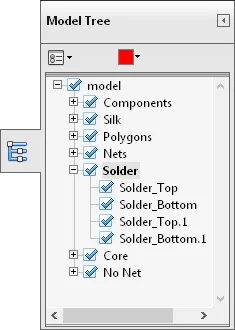
The Model Tree navigation pane is particularly useful
for controlling the display of specific components and nets.
The Model Tree navigation pane offers a powerful way to examine all aspects of a 3D design to a high degree of detail. Whether it’s a close examination of the component positioning and layout or a detailed inspection of the internal board structure, the navigation tree can be used to find and display the appropriate objects.

The design displayed with components and board overlays deselected, illustrating the degree of 3D control available in Acrobat Reader.
When selected in the Model Tree pane, individual objects are highlighted in the view window with the color defined at the top of the pane (red in this case). This makes locating a particular component or net simple and avoids the need to toggle an object's visibility to find its location. Similarly, selecting an object in the 3D view window highlights its entry in the Model Tree pane.
For more information on using the various controls, functions and settings in Acrobat Reader see the relevant Adobe help content: Displaying 3D Models in PDFs.
Basic design metadata from Altium Designer is also included in an exported PDF 3D document. The data includes the design source file, its author, the Altium Designer version, creation/modification dates, etc. The information can be viewed in Adobe Reader under the Description tab in the Document Properties dialog – File » Properties.
PDF 3D OutJob export
To include a PDF 3D file export in a project OutJob, click Add New Documentation Output under the Documentation Outputs entry, select PDF3D then select the desired document source - either a specific PCB document to export (or [PCB Document] to keep the OutJob generically reusable).
 Adding a PDF3D output generator to an Output Job Configuration file.
The PDF 3D generation settings can be pre-configured by selecting the entry for the output generator, right-clicking then choosing Configure from the context menu. This opens the Export 3D configuration dialog (as outlined previously).
When the Output Job is run or manually instigated, the PDF 3D file will be exported as defined in the OutJob's Output Containers section. This is to the configured managed content server and path, or the local/remote publishing target defined on the Data Management – Publishing Destinations page of the Preferences dialog.

Generating a 3D PDF file to a defined PDF output container, from within a configured OutJob.
