最初原理图是在纸上绘制时,往往画在一张足够铺满大型绘图台的单张大纸上,然后用专用的大幅面复印机进行复制。时代已经改变,如今原理图在台式 PC 上绘制,存储在服务器上,并用小幅面激光打印机打印出来。
这种变化意味着,即使是一个简单的设计,如果分布在多张原理图页上展示,也更容易显示和理解。即便设计并不特别复杂,将其组织到多张图纸上也可能带来优势。
例如,设计可能包含各种模块化元素。将这些模块作为独立文档维护,可以让多位设计人员同时在同一个项目上工作。把设计拆分为逻辑模块也能显著提升可读性——这对那些在产品生命周期后期需要阅读并解读原理图的人来说尤为重要。另一个优势是,当设计分布在多张图纸上且每张图纸的元件更少时,就可以使用激光打印机等小幅面打印方式。
如果你计划将设计分布到多张图纸上,需要做出两个决定:
-
图纸之间的结构关系,以及
-
用于在这些图纸上的电路之间建立电气连接的方法。
你的选择会因每个项目的规模与类型以及个人偏好而有所不同。
平面或层次化设计
如前所述,作为设计者,你需要决定原理图页如何组织,以及这些图纸之间如何建立连通性。不过这两者并不是彼此独立的决定,因为在选择结构的同时,你也需要选择将如何创建这些图纸之间的连接。
多图纸设计的结构有两种方式:flat 或 hierarchical。
两种方式都可行; 各自都有优缺点。平面设计创建更快,但对他人来说更难跟踪信号并理解功能,尤其是从打印件上阅读时。 层次化设计绘制耗时更长,因为创建连通性需要更多步骤,但回报是他人更容易理解其功能,并能跨图纸跟踪信号。层次化设计对于设计复用也很重要,并且是 multi-channel design 的关键组成部分。
平面设计
你可以把平面设计理解为:将一张很大的原理图切分成若干张较小的图纸——在平面设计中,所有图纸都处于同一层级。平面设计中的连通性可以从任意一张图纸直接连接到另一张图纸——这种连通性称为水平连通(horizontal connectivity)。
在平面设计中,顶层图纸(top sheet)是可选的。如果包含顶层图纸,它会为设计中的每一张图纸放置一个图纸符号(sheet symbol),但不能包含任何连线。平面设计中的图纸数量不受限制。

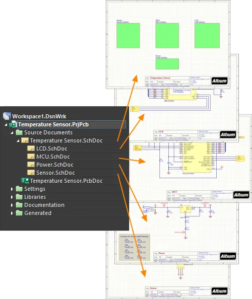
第一张图——平面设计没有顶层图纸;第二张图——同一设计包含顶层图纸。注意顶层图纸没有任何连线,它只是展示设计中的各张图纸。
上面的两张图都展示了平面设计:左侧版本没有顶层图纸,右侧版本有。对于只有两三张原理图页的小型设计,你可能会认为顶层图纸并不能增加价值。一旦图纸数量增多,顶层图纸可以通过顶层图纸上逻辑块(图纸符号,Sheet Symbols)的排列方式,帮助读者理解电路设计的功能。由于没有层次结构,设计中的所有图纸在 Projects panel 中都显示在同一层级。
Sheet Symbol

已放置的图纸符号
概述
图纸符号是一种电气设计基本对象(primitive)。它用于在多图纸层次化设计中表示一个子图纸。图纸符号包含图纸入口符号(sheet entry symbols),用于在层次化设计中为父图纸与子图纸之间的信号提供连接点,类似于在平面多图纸设计中 Ports 为图纸之间提供连接的方式。
可用性
图纸符号仅可在原理图编辑器中放置。可通过以下方法之一访问放置命令:
-
从主菜单中选择 Place » Sheet Symbol 。
-
在位于设计空间顶部的 Active Bar 上的图形对象下拉菜单中,点击 Sheet Symbol 按钮(
 ) 。(点击并按住某个 Active Bar 按钮可访问其他相关命令。某个命令一旦被使用,它将成为该 Active Bar区域的最上层条目。)
-
在设计空间中右键单击,然后从上下文菜单中选择 Place » Sheet Symbol。
-
在 Wiring 工具栏上点击 。
放置
启动命令后,光标会变为十字准星并进入图纸符号放置模式。放置可通过以下操作完成:
-
单击或按 Enter 以锚定图纸符号的第一个角点。
-
移动光标以调整图纸符号大小,然后单击或按 Enter 完成放置。
-
继续放置更多图纸符号 或右键单击或按 Esc 退出放置模式。
在放置过程中,当图纸符号仍悬浮在光标上且其第一个角点尚未锚定之前,还可以执行以下附加操作:
-
按 Tab 键访问 Properties panel 的 Sheet Symbol mode,可在放置过程中即时更改图纸符号属性。点击设计空间的暂停按钮叠层(
 )以继续放置。
-
按住 Alt 键,可根据初始移动方向将移动方向约束为水平或垂直轴。
-
按 Spacebar 将图纸符号逆时针旋转,或按 Shift+Spacebar 顺时针旋转。旋转以 90° 为增量。
-
按 X 或 Y 键,使图纸符号沿 X 轴或 Y 轴镜像。
虽然可以在放置过程中修改属性(
Tab 以访问
Properties panel),但请注意:除非在
Preferences dialog 的
Schematic – Defaults 页面启用了
Permanent 选项,否则这些修改将成为后续放置的默认设置。启用该选项后,所做更改只会影响正在放置的对象以及同一次放置会话中随后放置的对象。
图形化编辑
这种编辑方式允许你在设计空间中直接选择已放置的图纸符号对象,并以图形方式更改其大小、形状或位置。
当选中图纸符号对象时,你可以单击并拖动编辑手柄来调整图纸符号大小。

已选中的图纸符号
在图纸符号上避开编辑手柄的位置单击并拖动,可重新定位它。拖动时,图纸符号可以旋转(Spacebar/Shift+Spacebar)或镜像(按 X 或 Y 键沿 X 轴或 Y 轴镜像)。
调整图纸符号大小不会影响其中任何已定义图纸入口(sheet entries)的绝对位置。
图纸符号的 Designator 和 File Name 文本字段只能通过更改所用字体大小来调整(通过相应对象的 Properties panels 访问)。因此,当选中这两个对象之一时,不会显示编辑手柄。

图纸符号的已选中 Designator 和 Filename
-
在虚线框内任意位置单击并拖动,可按需重新定位文本对象。拖动时,文本可以旋转(Spacebar/Shift+Spacebar)或镜像(按 X 或 Y 键沿 X 轴或 Y 轴镜像)。
对象的文本可以通过以下方式进行就地编辑:
-
单击一次标号(Designator)或文件名文本以选中它。
-
再次单击一次(或按下 Enter)进入就地编辑模式。两次单击之间应留出足够时间,以确保软件不会将两次单击识别为一次双击(双击会打开关联的 Properties panel)。
-
完成就地文本编辑时,按 Enter 或用鼠标单击文本对象以外的区域。
如果尝试以图形方式修改启用了其 Locked 属性的对象,将弹出对话框要求确认是否继续编辑。如果在 Preferences dialog 的 Schematic – Graphical Editing 页面中启用了 Protect Locked Objects 选项,并且该设计对象的 Locked 选项也同样启用,则该对象将无法被选中或进行图形编辑。单击被锁定的对象以选中它,然后在 List panel 中禁用 Locked 属性,或禁用 Protect Locked Objects 选项,以便对该对象进行图形编辑。
非图形编辑
以下提供非图形编辑方法。
通过 Sheet Symbol 对话框或 Properties 面板编辑
Properties page: Sheet Symbol 属性
此编辑方法使用关联的 Sheet Symbol 对话框以及 Properties 面板的 Properties 模式来修改 sheet symbol 对象的属性。

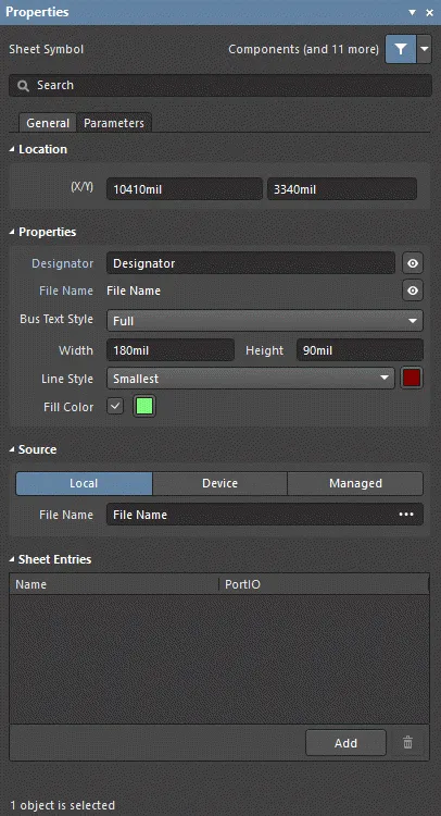
左侧为 Sheet Symbol dialog,右侧为 Properties 面板的 Sheet Symbol 模式
放置后,可通过以下方式访问 Sheet Symbol dialog:
-
双击已放置的 sheet symbol 对象。
-
将光标悬停在 sheet symbol 对象上,右键单击,然后从上下文菜单中选择 Properties。
在放置过程中,可按 Tab 键访问 Properties panel 的 Sheet Symbol 模式。sheet symbol 放置完成后,将显示所有选项。
放置后,可通过以下方式之一访问 Properties panel 的 Sheet Symbol 模式:
-
如果 Properties panel 已处于活动状态,选择该 sheet symbol 对象即可。
-
选中 sheet symbol 对象后,通过设计空间右下角的 Panels button 选择 Properties panel,或选择 View » Panels » Properties。
如果在
Preferences dialog 的
Schematic - Graphical Editing 页面中禁用了
Double Click Runs Interactive Properties 选项(默认),当双击该 primitive,或在选中 primitive 后右键并选择
Properties 时,将打开对话框。当启用
Double Click Runs Interactive Properties 选项时,将打开
Properties panel。
尽管对话框与面板中的选项相同,但选项的顺序和布局可能会略有不同。
在进入放置模式之前,可在
Preferences dialog 的
Schematic – Defaults 页面访问 sheet symbol 属性。这允许更改 sheet symbol 对象的默认属性,并在后续放置 sheet symbols 时应用这些默认值。
编辑多个对象
Properties panel 支持多对象编辑,可修改当前所选对象中相同的属性设置。当手动选择多个相同类型的对象,或通过 Find Similar Objects dialog ,或通过 SCH Filter 或 SCH List panel 进行选择时,Properties panel 中未显示为星号(*)的字段条目可对所有选中对象进行编辑。
通过列表面板编辑
Panel pages: 列表面板、SCH Filter
List panel 允许以表格形式显示一个或多个文档中的设计对象,从而快速检查并修改对象属性。结合适当的过滤(使用相应的 Filter panel,或 Find Similar Objects dialog),可仅显示落在当前活动过滤范围内的对象——从而更准确、更高效地定位并编辑多个设计对象。
Sheet Symbol 操作
格式化标号与文件名
sheet symbol 的 Designator 与 File Name 字段可独立于 sheet symbol 本体进行格式化。可使用上述“放置后”的方法访问相应的 Properties panels(将 sheet symbol 替换为你要查看/修改其属性的相关对象)。
sheet symbol 的
File Name (在
Properties panel 的
Sheet Symbol mode 中设置)必须设置为该符号所代表的原理图页的文件名。
右键 Sheet Symbol 命令
在已放置的 sheet symbol 上右键单击可打开与上下文相关的菜单,其中(在 Sheet Symbol Actions 子菜单中)提供以下对该 sheet symbol(或在适用时对当前选中的所有 sheet symbols)生效的命令。

-
Open SubSheet "<SheetName.SchDoc>" - 用于访问该符号引用的子原理图页;该页将被打开(若尚未打开)并在主设计窗口中成为活动文档。
-
Create Sheet From Sheet Symbol - 用于根据 sheet symbol 创建新的原理图文档,并在该文档中添加与符号上每个 sheet entry 对应的 port。通过这种方式,你可以基于在顶层原理图中创建并放置的 sheet symbols,自动为多页原理图设计创建子页。
创建的原理图文档将使用 sheet symbol 的 File Name field 中的条目来命名。你可以在执行该命令前在此字段中输入预期的文档名称(包含扩展名,即 DocumentName.SchDoc),或将名称留空,稍后在保存生成的文档时再输入名称。
当基于 sheet symbol 创建 sheet 时,如果同名文件的 sheet 已存在,需要特别注意。系统会创建一个具有相同文件名的新 sheet。保存时可通过将新 sheet 另存为不同名称,或在需要时覆盖现有 sheet 来解决重复问题。
-
Rename Child Sheet (也可通过主菜单选择 Design » Rename Child Sheet 命令访问)- 用于快速重命名 sheet symbol 引用的子原理图页。将打开 Rename Child Sheet dialog。

Rename Child Sheet dialog
在 New child sheet file name field 中指定原理图页的新名称,并确保保留 .SchDoc 扩展名。同时,从以下选项中确定重命名的执行方式(操作范围):
-
Rename child document and update all relevant sheet symbols in the current project – 启用此选项可重命名子 sheet,并更新活动工程中所有指向该 sheet 的源原理图上的所有 sheet symbols。每个 sheet symbol 的 File Name 将更新为反映新命名的子 sheet。
-
Rename child document and update all relevant sheet symbols in the current workspace – 启用此选项可重命名子 sheet,并更新所有已打开工程中所有指向该 sheet 的源原理图上的所有 sheet symbols。每个 sheet symbol 的 File Name 将更新为反映新命名的子 sheet。
-
Copy the child document and only update the current sheet symbol – 启用此选项可在重命名原始子 sheet 之前先复制一份子 sheet。使用此选项时,仅更新当前(光标所在)的 sheet symbol。 该 sheet symbol 的 File Name field 将更新为引用复制后的子 sheet。
当当前子 sheet 被多个 sheet symbols 引用,而其中一个 sheet symbol 需要引用该 sheet 上电路的修改版本时,复制子 sheet 非常有用。你仍希望保留原始 sheet,只是创建该 sheet 的一个重命名副本,并让单个 sheet symbol 指向它。随后即可按需修改复制 sheet 的内容。
-
Synchronize Sheet Entries and Ports - 用于同步该 sheet symbol 的 sheet entries 与子 sheet ports。将打开 Synchronize Ports To Sheet Entries dialog。使用此对话框可确保 sheet symbol 上的所有 sheet entries 与其所引用的下层子 sheet 上的 ports 在名称与 I/O Type 两方面都一致匹配。
-
Flip Sheet Symbol Along X - 用于沿 X 轴翻转 sheet symbol。与该符号关联的 sheet entries 将在水平方向上交换到符号的另一侧:左侧的会移到右侧,反之亦然。 sheet entries 的 I/O Type 不会改变。

沿 X 轴翻转 sheet symbol 的示例
如果当前选中了一个或多个 sheet symbols,该命令将显示为 Flip Selected Sheet Symbols Along X。该命令也可从主菜单的 Edit » Move 子菜单以及 Active Bar 中使用。翻转多个选中的 sheet symbols 时,这些符号将围绕一条假想的垂直线进行翻转,该垂直线位于所选符号边界范围的中点位置。
-
Flip Sheet Symbol Along Y- 用于沿 Y 轴翻转 Sheet Symbol。与该符号关联的 Sheet Entry 将基本上被交换到符号的另一侧(垂直方向平面上)。位于顶部的会被重新定位到底部,反之亦然。 Sheet Entry 的 I/O Type 不会被改变。

沿 Y 轴翻转 Sheet Symbol 的示例
如果当前选中了一个或多个 Sheet Symbol,该命令将显示为 Flip Selected Sheet Symbols Along Y。该命令也可从主菜单的 Edit » Move 子菜单以及 Active Bar 中使用。翻转多个已选 Sheet Symbol 时,这些符号将沿一条假想的水平线翻转,该水平线位于所选符号边界范围的中间位置。
-
Toggle All Sheet Entries IO Type in Sheet Symbol - 用于在适用情况下,同时切换该 Sheet Symbol 中所有 Sheet Entry 的 I/O Type。也可以通过在 Edit » Move 主菜单中点击 Toggle All Sheet Entries IO Type In (Selected) Sheet Symbols 或从 Active Bar 中使用。
 切换 Sheet Entry I/O 的示例结果
实际变化取决于当前的 PortIO Type,如下所示:
-
Unspecified 保持为 Unspecified。
-
Output 更改为 Input。
-
Input 更改为 Output。
-
Bidirectional保持为 Bidirectional。
说明
-
如果将一组 Sheet Entry 粘贴到已选中的 Sheet Symbol 中,并且这些条目落在符号当前边界之外,符号将自动调整大小以容纳它们。
-
通过使用 Sheet Symbol 实例化(instantiation),可以从单个 Sheet Symbol 引用同一子图纸上的多个通道。其语法是在 Sheet Symbol 的 Designator 字段中使用 Repeat 关键字,形式为:
Repeat(SheetSymbolDesignator, FirstInstance, LastInstance),
其中 SheetSymbolDesignator 是 Sheet Symbol 的基名,FirstInstance 与 LastInstance 共同定义要实例化的通道数量。
-
单个 Sheet Symbol 可以引用多个子图纸。在 File Name 字段中用分号分隔每个文件名。通过在子图纸上有效使用 Off-Sheet Connector,你可以将设计的一部分分布到多张图纸上,并将它们视为一张巨大的(扁平的)图纸来处理。但请注意,Off-Sheet Connector 仅适用于由同一个 Sheet Symbol 引用的图纸。
-
可使用
SheetSymbolDesignator 特殊字符串。该特殊字符串可放置在子原理图页上,用于显示放置在父原理图页上的关联 Sheet Symbol 对象的标号(designator)。该特殊字符串也可用于多通道设计。选择子原理图页的某个已编译(compiled)选项卡,以显示该特殊字符串转换后的值。
-
你可以通过从主菜单选择 Edit » Move » Reverse Selected Sheet Entries Order 命令,或在 Active Bar 上找到并使用 Reverse Selected Sheet Entries Order 命令,来反转所选 Sheet Entry 沿父 Sheet Symbol 某一侧的显示顺序。要使该命令生效,必须在 Sheet Symbol 的同一侧选择两个或更多 Sheet Entry。你可以同时对同一个父 Sheet Symbol 的不同侧、以及当前原理图页上不同 Sheet Symbol 的 Sheet Entry 进行重排。启动命令后将执行重排。重排通过将所选 Sheet Entry(沿某一 Sheet Symbol 边)的位置关于一条假想线进行镜像来实现,该假想线位于最外侧两条所选 Sheet Entry 边界范围距离的中点处。 重排不会改变 Sheet Entry 的 I/O Type 。
Sheet Symbol Properties
原理图编辑器对象属性是一些可定义的选项,用于指定已放置对象的视觉样式、内容和行为。每种对象类型的属性设置通过两种不同方式定义:
-
Pre-placement settings – 大多数 Sheet Symbol 对象属性,或那些在逻辑上可预先定义的属性,可在 Preferences 对话框的 Schematic - Defaults 页面中作为可编辑的默认设置使用(通过设计空间右上角的
 按钮进入)。在 Primitive List 中选择对象,即可在右侧显示其选项。

-
Post-placement settings – 当在设计空间中选中已放置的 Sheet Symbol 时,所有 Sheet Symbol 对象属性都可在 Sheet Symbol 对话框和 Properties 面板中编辑。
如果在
Preferences dialog 的
Schematic - Graphical Editing page 中禁用
Double Click Runs Interactive Properties 选项(默认),当双击该图元,或在选中图元后右键并选择
Properties 时,将打开对话框。当启用
Double Click Runs Interactive Properties 选项时,将打开
Properties panel。
尽管对话框与面板中的选项相同,但选项的顺序和布局可能略有不同。
在下面的属性列表中,无法在 Preferences dialog 中作为默认设置提供的选项会标注为“Properties panel only”。
General Tab
Location (Properties panel only)
-
(X/Y)
-
X (第一个字段)- 对象参考点相对于当前设计空间原点的当前 X(水平)坐标。编辑以更改对象的 X 位置。数值可用公制或英制输入;当输入的单位不是当前默认单位时,请在数值中包含单位。
-
Y (第二个字段)- 对象参考点相对于当前原点的当前 Y(垂直)坐标。编辑以更改对象的 Y 位置。数值可用公制或英制输入;当输入的单位不是当前默认单位时,请在数值中包含单位。
Properties
Source (Properties panel only)
-
Local / Device / Managed- 文件的来源。
-
File Name - 显示 由该页符号引用的当前原理图文档。正是此字段提供了页符号与该符号所代表的原理图子页之间的链接。单击
 以打开
以打开 ![]() 选择要引用的文档对话框,从而选择所需的目标子页。该对话框会列出项目中所有源原理图页(不包括当前放置该符号的那一页)。
选择要引用的文档对话框,从而选择所需的目标子页。该对话框会列出项目中所有源原理图页(不包括当前放置该符号的那一页)。
一个页符号可以引用多个子页。在 File Name 字段中用分号分隔每个文件名。通过在子页上有效使用跨页连接器(off-sheet connectors),你可以将设计的某一部分分布在多个页面上,并将其视为一张巨大的(扁平的)单页来处理。但请注意,跨页连接器只能用于由同一个页符号引用的页面。
Sheet Entries (Properties 仅面板
-
Grid)- 列出当前为该页符号定义的所有 sheet entry 的 Name 和 PortIO Type 。当网格中存在 sheet entry 时,选中某个条目后将提供以下附加选项:
-
Font - 单击以配置 sheet entry 的字体样式。
-
Other - 单击以打开下拉菜单并更改其他选项:
-
Kind - 使用下拉菜单选择 sheet entry 的类型。
-
Border Color - 单击以访问用于选择边框颜色的控件。
-
Fill Color - 单击以访问用于选择填充颜色的控件。
-
Add - 单击以添加一个 sheet entry。使用
 从表格中删除所选条目。
Parameters Tab

Parameters
-
Grid - 列出当前为该页符号定义的所有参数的 Name 和 Value。当网格中存在参数时,选中某个参数后将提供以下附加选项:
-
Font - 单击以配置参数的字体样式。
-
Other - 单击以打开下拉菜单并更改其他选项:
-
Show Parameter Name - 启用后在设计空间中显示参数名。
-
Allow Synchronization with Database - 启用后与数据库同步。此选项用于控制注释(comment)是否可被更新。默认情况下,这些选项处于启用状态,以始终允许与源库/数据库同步。你可以禁用此选项,以防止该注释被包含在更新过程中。
-
X/Y - 输入所需的 X 与 Y 坐标。
-
Rotation - 使用下拉菜单选择旋转角度。
-
Autoposition - 勾选以启用自动定位,这意味着当元件移动和旋转时,文本将保持在所选位置。
-
Add - 单击以添加一个参数。使用 从表格中删除所选条目。
Sheet Symbol Designator

Sheet Symbol Designator
摘要
页符号标号(sheet symbol designator)是电气设计图元的一个非电气子对象。它用于为页符号提供一个有意义的名称,以便将其与同一原理图页上放置的其他页符号区分开来。通常,该名称会反映该符号所代表的原理图子页的整体功能。
可用性与放置
当放置父级元件部件对象时,页符号标号会自动放置。它不是用户可以直接放置的设计对象。
在放置页符号期间对
Designator 字段所做的任何更改,都会导致页符号标号对象的默认属性被更新,除非在
Preferences 对话框
Permanent 的
Schematic - Defaults 页面上启用了该
Permanent 选项。启用该选项后,所做的更改只会影响当前正在放置的页符号对象的标号,以及同一次放置会话中随后放置的页符号对象。
图形化编辑
此编辑方法允许你在设计空间中直接选择页符号标号对象,并以图形方式更改其位置。页符号标号只能通过在 Properties panel 中更改 Font 的大小来调整其尺寸。因此,当选中页符号标号对象时,不会提供编辑手柄:

已选中的页符号标号
在虚线框内任意位置单击并拖动,以按需重新定位页符号标号对象。拖动时可对对象进行旋转或镜像翻转:
-
按 Tab 键以打开 Properties 面板,从而可即时更改页符号标号的属性。
-
按 Alt 键可将移动方向约束为水平或垂直轴,具体取决于初始移动方向。
-
按 Spacebar 可将页符号标号逆时针旋转,或按 Shift+Spacebar 顺时针旋转。旋转以 90° 为增量。
-
按 X 或 Y 键可沿 X 轴或 Y 轴镜像页符号标号。
如果在
Preferences对话框
In-Place Editing的
Schematic - General 页面上启用了 Enable
In-Place Editing 选项,你将能够在设计空间中直接编辑页符号标号的名称。选中标号后单击一次以调用该功能。按需输入新名称,然后在页符号标号字段外单击,或按
Enter 以使更改生效。
如果尝试以图形方式修改启用了 Locked 属性的对象,将弹出对话框要求确认是否继续编辑。如果在 Preferences 对话框Protect Locked Objects的 Schematic – Graphical Editing 页面上启用了 Protect Locked Objects 选项,并且该设计对象的 Locked 选项也已启用,则该对象无法被选中或进行图形化编辑。单击被锁定的对象以选中它,然后在 List panel 中禁用 Locked 属性,或禁用 Protect Locked Objects 选项,以便对该对象进行图形化编辑。
非图形化编辑
以下提供非图形化编辑方法。
通过 Parameter 对话框或 Properties 面板进行编辑
Panel page: Sheet Symbol Designator Properties此编辑方法使用关联的 Parameter 对话框以及 Properties 面板的 Properties 模式来修改页符号标号对象的属性。

 左侧为 Parameter 对话框,右侧为 Properties 面板的 Parameter 模式
放置后,可通过以下方式访问 Parameter 对话框:
-
双击已放置的页符号标号对象。
-
将光标悬停在页符号标号对象上,右键单击,然后从上下文菜单中选择 Properties。
在放置过程中,可按 Tab 键访问 Properties 面板的 Parameter 模式。页符号标号放置完成后,将显示所有选项。
放置后,可通过以下方式之一访问 Properties 面板的 Parameter 模式:
-
如果 Properties 面板已处于活动状态,选择页符号标号对象即可。
-
选中页符号标号对象后,通过设计空间右下角的 Panels 按钮选择 Properties 面板,或选择 View » Panels » Properties。
如果在
Preferences 对话框的
Schematic - Graphical Editing page 上禁用了
Double Click Runs Interactive Properties 选项(默认),当双击该图元,或在选中图元后右键并选择
Properties 时,将打开对话框。当启用
Double Click Runs Interactive Properties 选项时,将打开
Properties 面板。
尽管对话框与面板中的选项相同,但选项的顺序与布局可能略有不同。
在进入放置模式之前,可从
Preferences 对话框的
Schematic – Defaults 页面访问页符号标号属性。这允许更改页符号标号对象的默认属性,并在随后放置页符号标号时应用这些默认属性。
编辑多个对象
Properties 面板支持多对象编辑,可修改当前所选对象中相同的属性设置。当手动选择多个相同对象类型,或通过 Find Similar Objects 对话框,或通过 Filter 或 List 面板进行选择时,Properties 面板中未显示为星号(*)的字段条目可对所有选中对象进行编辑。
通过 List 面板进行编辑
Panel pages: 列表面板、SCH 过滤器、SCHLIB 过滤器
一个 List 面板允许你以表格形式显示来自一个或多个文档的设计对象,从而能够快速检查并修改对象属性。配合适当的过滤一起使用——通过使用相应的 Filter 面板,或 查找相似对象对话框——它可以仅显示落在当前活动过滤器范围内的对象,从而让你更准确、更高效地定位并编辑多个设计对象。
注释
-
虽然文本框可以沿 X 或 Y 轴旋转或镜像,但这不会影响其中文本的朝向。
-
对于简单的单行文本标注,建议使用 Text String 对象。
-
通过使用页符号实例化(sheet symbol instantiation),同一子页上的多个通道可以通过一个页符号来引用。所用语法是在页符号的 标号(designator)字段中使用 Repeat 关键字,形式为:
Repeat(SheetSymbolDesignator, FirstInstance, LastInstance)。

使用 Repeat 关键字
SheetSymbolDesignator时,Repeat 是页符号的基名称,而 FirstInstance 与 LastInstance 一起定义要实例化的通道数量。构建项目时,编译器在构建内部编译模型的过程中,会按所需次数实例化该通道,并使用选定的标注方案为每个通道中的每个元件提供唯一标识。通道子原理图不会被复制。相反,编译完成后,在主设计窗口中该子页文档底部会为该页上的每个通道显示一个单独的选项卡。
当在“项目选项”对话框的
Options 选项卡中启用
New Indexing of Sheet Symbols 选项时,重复的 Sheet Symbol 的首/末索引可以使用任意数字(包括 0);末索引必须始终大于首索引,且不允许使用负数。
-
可使用
SheetSymbolDesignator 特殊字符串。该特殊字符串可放置在子原理图页上,用于显示放置在父原理图页上的关联 Sheet Symbol 对象的标号。该特殊字符串也可用于多通道设计。选择子原理图页的某个已编译选项卡,以显示该特殊字符串转换后的值。
Sheet Symbol Designator Properties
原理图编辑器对象属性是一些可定义选项,用于指定已放置对象的视觉样式、内容与行为。每种对象类型的属性设置通过两种不同方式定义:
如果在
Preferences 对话框的
Schematic - Graphical Editing 页面上禁用(默认)
Double Click Runs Interactive Properties 选项,则当双击该图元,或在选中图元后右键并选择
Properties 时,将打开对话框。当启用
Double Click Runs Interactive Properties 选项时,将打开
Properties 面板。
尽管对话框与面板中的选项相同,但选项的顺序与布局可能略有不同。
在下面的属性列表中,未在 Preferences 对话框Properties中作为默认设置提供的选项会标注为“Properties仅面板”。
位置 (Properties 仅面板
-
(X/Y)
-
X) (第一个字段)- 对象参考点相对于当前设计空间原点的当前 X(水平)坐标。编辑以更改对象的 X 位置。数值可用公制或英制输入;当输入的单位不是当前默认单位时,请在数值中包含单位。
-
Y (第二个字段)- 对象参考点相对于当前原点的当前 Y(垂直)坐标。编辑以更改对象的 Y 位置。数值可用公制或英制输入;当输入的单位不是当前默认单位时,请在数值中包含单位。
-
Rotation - 使用下拉列表选择旋转角度。
属性
Sheet Symbol File Name
Sheet Symbol 文件名
概述
Sheet Symbol 文件名是电气设计图元的一个非电气子对象。它提供了页符号与该符号所代表的原理图子页之间的链接。
可用性与放置
当放置父级页符号对象时,会自动放置 Sheet Symbol 文件名。它不是用户可以直接放置的设计对象。
虽然在放置过程中可以修改属性(
Tab 以访问
Properties 面板),但请注意:除非启用
Preferences 对话框的
Schematic – Defaults 页面上的
Permanent 选项,否则这些修改将成为后续放置时的默认设置。启用该选项后,所做更改只会影响正在放置的对象,以及同一次放置会话中随后放置的对象。
图形化编辑
此编辑方法允许你在设计空间中直接选择一个 Sheet Symbol 文件名对象,并以图形方式更改其位置。Sheet Symbol 文件名只能通过在属性面板中更改 Font 的大小来调整其尺寸。因此,当选中 Sheet Symbol 文件名对象时,不会提供编辑手柄。
 在虚线框内任意位置单击并拖动,以按需重新定位 Sheet Symbol 文件名对象。拖动时可旋转或翻转该对象。
按 Spacebar 可旋转文件名。旋转以逆时针方向每次 90° 递增。
如果在
Preferences 对话框的
Schematic - General 页面上启用了 Enable
In-Place Editing 选项,你将能够在设计空间中直接编辑 Sheet Symbol 文件名的名称。选择该标号后再单击一次以调用该功能。按需输入新名称,然后单击远离 Sheet Symbol 文件名处或按
Enter 以使更改生效。
如果尝试以图形方式修改某个启用了其 Locked 属性的对象,将会弹出一个对话框,要求确认是否继续编辑。如果在 Preferences 对话框的 Schematic – Graphical Editing 页面上启用了 Protect Locked Objects 选项,并且该设计对象的 Locked 选项也同样启用,那么该对象将无法被选中或进行图形编辑。单击被锁定的对象以选中它,然后在 List panel 中禁用 Locked 属性,或禁用 Protect Locked Objects 选项,以便对该对象进行图形编辑。
非图形编辑
以下提供了非图形编辑的方法。
通过参数对话框或 Properties 面板编辑
Panel page: Sheet Symbol File Name Properties
此编辑方法使用关联的 Parameter dialog 以及 Properties panel 模式来修改 sheet symbol file name 对象的属性。

 左侧为 Parameter dialog,右侧为 Properties 面板的 Parameter 模式
放置完成后,可通过以下方式访问 Parameter dialog:
-
双击已放置的 sheet symbol 对象。
-
将光标置于 sheet symbol 对象上,右键单击,然后从上下文菜单中选择 Properties。
在放置过程中,可按 Tab 键访问 Properties panel 的 Parameter 模式。sheet symbol 放置完成后,将显示所有选项。
放置完成后,可通过以下方式之一访问 Properties panel 的 Parameter 模式:
-
如果 Properties panel 已处于活动状态,通过选择 Sheet Symbol 对象即可。
-
选中 sheet symbol 对象后,通过设计空间右下角的 Panels button 选择 Properties panel,或选择 View » Panels » Properties。
如果在
Preferences dialog 的
Schematic - Graphical Editing page 上禁用了(默认)
Double Click Runs Interactive Properties 选项,那么当双击该 primitive,或在选中 primitive 后右键并选择
Properties 时,将打开对话框。当启用
Double Click Runs Interactive Properties 选项时,将打开
Properties panel。
尽管对话框与面板中的选项相同,但选项的顺序和布局可能会略有不同。
在进入放置模式之前,可从
Preferences 对话框的
Schematic – Defaults 页面访问 sheet symbol file name 属性。这允许更改 sheet symbol file name 对象的默认属性,并会在后续放置 sheet symbol file names 时应用这些默认值。
编辑多个对象
Properties panel 支持多对象编辑,可修改当前所选对象中相同的属性设置。当手动选择多个相同对象类型,或通过 Find Similar Objects dialog,或通过 Filter 或 List panel 进行选择时,Properties panel 中未显示为星号(*)的字段条目,都可以对所有选中对象进行编辑。
通过列表面板编辑
Panel pages: List Panels、SCH Filter、SCHLIB Filter
List panel 允许以表格形式显示来自一个或多个文档的设计对象,从而快速检查并修改对象属性。结合适当的过滤(使用相应的 Filter panel,或 Find Similar Objects dialog),它可以仅显示落在活动过滤器范围内的对象——从而更准确、更高效地定位并编辑多个设计对象。
Sheet Symbol Filename Properties
Schematic Editor 对象属性是可定义的选项,用于指定已放置对象的视觉样式、内容和行为。每种对象类型的属性设置通过两种不同方式定义:

-
Post-placement settings – 当在设计空间中选中已放置的 Sheet Symbol Filename 时,所有 Sheet Symbol Filename 对象属性都可在 Parameter dialog 和 Properties panel 中编辑。
如果在
Preferences dialog 的
Schematic - Graphical Editing page 上禁用了(默认)
Double Click Runs Interactive Properties 选项,那么当双击该 primitive,或在选中 primitive 后右键并选择
Properties 时,将打开对话框。当启用
Double Click Runs Interactive Properties 选项时,将打开
Properties panel。
尽管对话框与面板中的选项相同,但选项的顺序和布局可能会略有不同。
在下面的属性列表中,无法在 Preferences dialog 中作为默认设置提供的选项会标注为“Properties panel only”。
位置 (Properties panel only)
-
Search - 使用此字段在 Properties panel 中搜索所需文本。找到后,搜索到的文本将被高亮显示。
-
(X/Y)
-
X (第一个字段)- 对象参考点相对于当前设计空间原点的当前 X(水平)坐标。编辑以更改对象的 X 位置。数值可使用公制或英制输入;当输入的单位不是当前默认单位时,请在数值中包含单位。
-
Y (第二个字段)- 对象参考点相对于当前原点的当前 Y(垂直)坐标。编辑以更改对象的 Y 位置。数值可使用公制或英制输入;当输入的单位不是当前默认单位时,请在数值中包含单位。
-
Rotation - 使用下拉列表选择旋转角度。
属性
-
Sheet Symbol - 与此对象关联的 sheet symbol。
-
Name - 显示名称。
-
Value - 显示实际的文件名文本。使用
 /
/  来确定该对象的 Value 是显示还是隐藏。 勾选 Autoposition 以启用自动定位。
-
Font - 使用控件配置字体、字号、颜色,以及加粗、下划线等特殊设置。
-
Justification - 选择所需的文本对齐方式。
层次化设计
需要牢记的是,对于层次化设计,一个项目只能包含一个顶层原理图(top sheet)。所有其他源文档都必须通过 sheet symbols 来引用。在执行设计验证时,可使用
Multiple Top Level Documents violation check 来标记是否存在不符合该规则的情况。此外,任何 sheet symbol 都不能引用其所在的那张 sheet,或引用层级中更高的任何 sheet,否则会在结构中形成无法解析的循环。
层次化设计是指在设计中呈现树状结构(或 sheet 与 sheet 之间的关系)。 这通过 sheet symbols 来实现,它们表示设计层次结构中的下级 sheets。该符号代表下方的 sheet,而其中的 sheet entries 则表示(或连接到)下方 sheet 上的 ports。 连通性是通过这些 Sheet Symbols 中的 Sheet Entries 实现的——而不是直接从一张 sheet 上的 Ports 连接到另一张 sheet 上的 Ports。
与扁平化设计一样,通过在 sheet symbol 中定义其文件名来标识子 sheet。在层次化设计中,该子 sheet 也可以包含 sheet symbols,用于引用更低层级的 sheets,从而在层次结构中创建新的层级。下图展示了一个具有 3 个层级的层次化设计。

在层次化设计中,树中显示的结构由 sheet symbols 创建的父子关系决定。
在层次化设计中,子 sheet 上的信号通过 Port 离开该 sheet,并向上连接到父 sheet 上匹配的 Sheet Entry。父 sheet 包含布线,将子信号传递到另一个 Sheet Symbol 中的 Sheet Entry,然后信号向下传递到第二个子 sheet 上匹配的 Port,如下图所示。

这种父子 sheet 结构可以定义到任意深度,并且层次化设计中可以包含任意数量的 sheets。
各 sheets 之间的连通性由 Net Identifier Scope 决定。该设置位于 Options for Project dialog 的 Options 选项卡中。要了解更多关于创建连通性的信息,请阅读 Creating Connectivity 页面。请注意,Net Identifier Scope 包含 Automatic 选项;除非你有特殊的连通性需求,否则该选项是一个不错的选择。
层次化设计的优势在于,它向读者展示了设计的结构,并且由于连通性始终是从子原理图页向上连接到父原理图页上的页符号,因此连通关系完全可预测且易于追踪。
层次化设计的另一个优势是,它为交付一套成熟的设计复用系统提供了平台。该系统根据数据的存储方式,以两种形式提供:基于文件或基于服务器。
Port
 已放置的 Port
摘要
Port 是一种电气设计基本对象(primitive)。它用于在使用多张原理图页(扁平或层次化设计)的设计中,在一张原理图页与另一张原理图页之间,或与页符号(通过对应的 sheet entry)之间建立电气连接。Port 的名称定义了连接关系(即:某张原理图页上的 Port 会连接到项目中其他原理图页上具有相同名称的 Port 或 sheet entry)。
请注意,
Cross Reference 功能会标识互连的
Ports 的位置,以及互连的跨页连接器(off sheet connectors)的网格位置引用。对于这两类原理图连接对象,现有的
Reports » Port Cross Reference » Add To Project 命令会基于目标原理图页名称和网格位置引用添加一个交叉引用参数。
可用性
Ports 可通过以下方式在原理图编辑器中放置:
-
从主菜单中单击 Place » Port 。
-
在设计空间顶部的 Active Bar 上,单击指令下拉菜单中的 Port 按钮(
 )。(单击并按住某个 Active Bar 按钮可访问其他相关命令。某个命令一旦被使用,它将成为该 Active Bar 区域的最上层条目。)
-
右键单击,然后选择 Place » Port。
放置
启动命令后,光标将变为十字准星,并进入 Port 放置模式。放置时按以下步骤操作:
-
单击或按 Enter 以锚定 Port 的左边缘。
-
移动光标按需调整 Port 的长度,然后单击或按 Enter 完成 Port 放置。
-
继续放置更多 Port,或右键单击/按 Esc 退出放置模式。
在放置过程中,当 Port 仍悬浮在光标上且其左边缘尚未锚定之前,还可以执行以下附加操作:
-
按 Tab 键暂停放置,并访问 Properties panel 的 Port mode,以便实时更改其属性。单击设计空间的暂停按钮叠层()以继续放置。
-
按 Spacebar 逆时针旋转 Port,或按 Shift+Spacebar 顺时针旋转。旋转以 90° 为增量。
-
按 X 或 Y 键,使 Port 沿 X 轴或 Y 轴镜像。
虽然可以在放置期间修改属性(Tab 以访问相关 Properties panel),但请记住:除非在 Preferences dialog 的 Schematic – Defaults 页面启用了 Permanent 选项,否则这些修改将成为后续放置的默认设置。启用该选项后,所做更改只会影响正在放置的对象以及同一次放置会话中随后放置的对象。
图形化编辑
此编辑方法允许你在设计空间中选择已放置的 Port 对象,并以图形方式更改其长度、高度或位置。
选中 Port 对象后,你可以单击并拖动编辑手柄来调整 Port 的大小。
 已选中的 Port
在 Port 上远离编辑手柄的位置单击,然后拖动以重新定位。拖动时,Port 可旋转(Spacebar/Shift+Spacebar)或镜像(按 X 或 Y 键沿 X 轴或 Y 轴镜像)。
Port 对象的名称可通过 in-place 以下方式编辑:
-
单击一次 Port 以选中它。
-
再次单击一次(或按 Enter)进入就地编辑模式。两次单击之间应留出足够时间,以确保软件不会将两次单击识别为一次双击(双击会打开 Properties panel)。
-
完成就地文本编辑后,按 Enter 或用鼠标单击 Port 之外的区域。
-
Port 会自动调整大小以适应 Port 名称的长度/高度。
如果尝试以图形方式修改启用了 Locked 属性的对象,将弹出对话框要求确认是否继续编辑。如果在 Preferences dialog 的 Schematic – Graphical Editing 页面启用了 Protect Locked Objects 选项,并且该设计对象的 Locked 选项也已启用,则该对象将无法被选中或进行图形化编辑。单击被锁定的对象以选中它,然后在 List panel 中禁用 Locked 属性,或禁用 Protect Locked Objects 选项,以便对对象进行图形化编辑。
非图形化编辑
提供以下非图形化编辑方法。
通过 Port 对话框或 Properties 面板编辑
Properties page: Port Properties
此编辑方法使用相关 Port dialog 以及 Properties panel 模式来修改 Port 对象的属性。

 左侧为 Port dialog,右侧为 Properties 面板的 Port 模式
放置后,可通过以下方式访问 Port dialog:
-
双击已放置的 Port 对象。
-
将光标悬停在 Port 对象上,右键单击,然后从上下文菜单中选择 Properties。
在放置期间,可按 Tab 键访问 Properties panel 的 Port mode。Port 放置完成后,将显示所有选项。
放置后,可通过以下方式之一访问 Properties panel 的 Port mode:
-
如果 Properties panel 已处于活动状态,选择 Port 对象即可。
-
选中 Port 对象后,通过设计空间右下角的 Panels button 选择 Properties panel,或从主菜单选择 View » Panels » Properties。
如果在
Preferences dialog 的
Schematic - Graphical Editing page 上禁用了
Double Click Runs Interactive Properties 选项(默认),当双击该 primitive,或在选中 primitive 后右键并选择
Properties 时,将打开对话框。启用
Double Click Runs Interactive Properties 选项后,将打开
Properties panel。
尽管对话框与面板中的选项相同,但选项的顺序和布局可能略有不同。
在进入放置模式之前,可从
Preferences dialog 的
Schematic – Defaults 页面访问 Port 属性。这允许更改 Port 对象的默认属性,并在后续放置 Port 时应用这些默认值。
编辑多个对象
Properties panel 支持多对象编辑,可修改当前所选对象中相同的属性设置。当手动选择多个相同对象类型,或通过 Find Similar Objects dialog ,或通过 SCH Filter 或 SCH List panel 进行选择时,Properties panel 中未显示为星号(*)的字段条目可对所有选中对象进行编辑。
通过列表面板编辑
Panel pages: 列表面板、SCH Filter
List panel 允许你以表格形式显示来自一个或多个文档的设计对象,从而快速检查并修改对象属性。结合适当的过滤(使用相应的 Filter panel 或 Find Similar Objects dialog),它可以仅显示落在活动过滤范围内的对象——使你能够更准确、更高效地定位并编辑多个设计对象。
Port 操作
在已放置的端口上单击右键,会弹出一个与上下文相关的菜单,其中提供以下可用命令(位于 Port Actions 子菜单中),这些命令作用于该端口(或在适用时作用于当前选中的所有端口):
-
Jump to Sheet Entry <PortName> - 用于跳转到父级页图符号中与该端口对应的页入口(Sheet Entry),该父级页图符号引用了端口所在的子页。
-
Toggle Port IO Type - 用于切换该端口的 I/O 类型。
实际更改取决于当前 I/O 类型,如下所示:
-
Unspecified 保持为 Unspecified。
-
Output 更改为 Input。
-
Input 更改为 Output。
-
Bidirectional 保持为 Bidirectional。
如果当前选中了多个端口,该命令将显示为 Toggle Selected Ports IO Type。该命令将应用于所有选中的端口。
-
Place Harness Connector of Type <HarnessConnectorType> - 用于放置一个线束连接器(包含各自已定义的线束条目),以连接到该端口。
此命令仅对已定义 Harness Type 的端口可用。
-
Jump to Port <PortName> on <SheetName> - 用于跳转到所指示源原理图文档中另一个同名端口。
Notes
-
端口与页图符号之间的关系由为项目选择的 Net Identifier Scope 决定。该作用域通过在 Project Options - Options dialog(Project » Project Options)中设置 Net Identifier Scope 选项来定义。
-
Properties panel 中的 I/O Type 选项允许你定义端口的电气类型。可从 Input、Output、Bidirectional 或 Unspecified 中选择。请注意:如果在 Preferences dialog 的 Schematic – General page 中启用了 Port Direction 选项,端口将自动显示 I/O 类型。
-
要对端口名称取反(在名称上方加一条横线),可使用以下方法之一:
-
默认情况下,端口名称不会用于为网络(net)命名。如果希望端口用于为其网络命名,请在 Options for Project dialog 的 Options 选项卡中启用 Allow Ports to Name Nets 选项。如果该选项被禁用,则在该网络没有关联网络标号(net label)或电源对象(power object),或在层次化设计中未启用 Allow Sheet Entries to Name Nets 选项时,将使用系统生成的网络名。了解更多:How Nets are Named。
-
端口会自动调整大小以适应端口名称的长度/高度。无论文本如何输入(使用 Properties panel 的 Port 模式,或 在设计空间中直接就地编辑),自动调整大小都有效。
-
当端口连接到信号线束(Signal Harness)时,端口会变为线束对象(Harness object)。默认情况下,端口会变更颜色以匹配信号线束的颜色。
-
当端口通过信号线束连接到线束连接器(Harness Connector)时,Properties panel 中的 Harness Type 会自动填充为该线束连接器的线束类型(Harness Type)。当端口通过信号线束连接到页入口(Sheet Entry),且该页入口声明了线束类型时,端口将变为线束对象并变更为信号线束的颜色。如果将端口移离线束连接器或页入口,端口将恢复为默认颜色。
-
默认情况下,端口的 Name 所使用的字体遵循文档级全局字体设置,该设置位于 Properties panel 的 Document Options mode 中的 Document Font 选项(当工作区未选中任何对象时)。这可以在单个端口级别通过 Properties panel 中的 Font 设置进行覆盖,从而按需完全控制端口的文本呈现方式。
-
当通过 Import Wizard 导入 OrCAD 设计时,在生成的原理图文档上支持自定义端口连接器。此类端口将与原始设计具有相同的图形。了解更多:Importing a Design from OrCAD。
-
当通过 Import Wizard 导入 xDX Designer 设计时,在生成的原理图文档上支持自定义端口。此类端口将与原始设计具有相同的图形。了解更多:Importing a Design from xDX Designer or DxDesigner。
Port Properties
原理图编辑器对象属性是一些可定义的选项,用于指定已放置对象的视觉样式、内容和行为。每种对象类型的属性设置通过两种不同方式定义:
-
Pre-placement settings – 大多数 Port 对象属性(或那些在逻辑上可预先定义的属性)可在 Preferences dialog 的 Schematic - Defaults 页面中作为可编辑的默认设置提供(通过设计空间右上角的 按钮进入)。在 Primitive List 中选择对象,即可在右侧显示其选项。

-
Post-placement settings – 当在设计空间中选中已放置的 Port 时,所有 Port 对象属性都可在 Port dialog 和 Properties panel 中编辑。
如果在
Preferences dialog 的
Schematic - Graphical Editing page 中禁用了
Double Click Runs Interactive Properties 选项(默认),当双击该图元,或在选中图元后右键并选择
Properties 时,将打开对话框。当启用
Double Click Runs Interactive Properties 选项时,将打开
Properties panel。
尽管对话框与面板中的选项相同,但选项的顺序和位置可能略有不同。
在下面的属性列表中,未作为 Preferences dialog 默认设置提供的选项会标注为“Properties panel only”。
General Tab
Location (Properties panel only)
-
(X/Y)
-
X (第一个字段)- 对象参考点相对于当前设计空间原点的当前 X(水平)坐标。编辑可更改对象的 X 位置。数值可用公制或英制输入;当输入的单位不是当前默认单位时,请在数值中包含单位。
-
Y (第二个字段)- 对象参考点相对于当前原点的当前 Y(垂直)坐标。编辑可更改对象的 Y 位置。数值可用公制或英制输入;当输入的单位不是当前默认单位时,请在数值中包含单位。
Properties
-
Name - 端口的名称。
-
I/O Type - 定义端口的电气属性。从下拉列表中选择一个选项。
此设置不会影响电路的连通性,但在执行电气规则检查(ERC)时会被纳入考虑,ERC 可设置为检测不兼容的端口方向。
-
Harness Type - 使用下拉列表选择线束类型。
-
Cross Ref - 此字段显示应用于端口的交叉引用值。
-
Width - 可编辑。
-
Height - 可编辑。
-
Font - 如有需要,使用控件选择所需字体、字号、颜色以及加粗、斜体等属性。
-
Alignment - 单击所需的对齐方式设置。
-
Border - 使用下拉列表从可用选项中选择默认值。单击彩色方块可打开下拉列表,从中选择默认颜色。
-
Fill - 单击颜色方块可打开下拉列表,从中选择默认颜色。
General (Net)
显示分配给该端口的网络属性。按需更新。
在将指令添加到对象之后,Power Net 和 High Speed 字段才会变为可用。
参数(网络)
-
Selection buttons - 单击所需对象以在网格中显示。
-
Add - 使用下拉列表添加所需对象,然后定义其值。
在将指令添加到对象之后,Add 按钮才会变为可用。
参数选项卡

参数
使用此区域来管理附加到当前所选端口对象的参数。
-
Grid - 列出当前为该端口定义的参数的 Name 和 Value 。如有需要,你可以直接编辑这些字段。使用 和 显示/隐藏该参数。使用锁定图标锁定/解锁所选参数。
-
Font Settings - 单击以打开用于定义字体的菜单。
-
Other - 单击以打开下拉列表以更改其他选项:
-
Show Parameter Name - 启用以显示参数名称。
-
Allow Synchronization with Database - 启用以与数据库同步。
-
X/Y - 输入 X 和 Y 坐标。
-
Rotation - 使用下拉列表选择旋转角度。
-
Autoposition - 勾选以启用自动定位。
-
Add - 单击 以添加参数。使用 从表中删除所选条目。
请注意,
交叉引用 功能用于识别互连的
端口 的位置,以及互连的跨页连接器的定位网格参考。对于这两类原理图连接对象,现有的
Reports » Port Cross Reference » Add To Project 命令会基于目标图纸名称和定位网格参考添加一个交叉引用参数。
Sheet Entry

已放置的 Sheet Entry
概述
Sheet Entry 是一种电气设计基元,属于 Sheet Symbol 内部。它放置在 Sheet Symbol 中,用于为该符号指定输入/输出端口。Sheet Entry 与该符号所代表的源原理图子页中放置的端口相对应。
可用性
在原理图编辑器中,Sheet Entry 仅可通过以下方式放置:
-
从主菜单中选择 Place » Sheet Entry 。
-
单击位于设计空间顶部的 Active Bar 上的图形对象下拉列表中的 Sheet Entry 按钮(
 )。(单击并按住某个 Active Bar 按钮可访问其他相关命令。某个命令一旦使用过,它将成为该 Active Bar 相应区域中的最上方条目。)
-
在设计空间中右键单击,然后从上下文菜单中选择 Place » Sheet Entry 。
-
单击 Wiring 工具栏上的 按钮。
放置
启动命令后,光标将变为十字准星,你将进入 Sheet Entry 放置模式。放置需按以下操作顺序进行:
-
将随光标移动的 Sheet Entry 移到图纸上已放置的 Sheet Symbol 上方。
-
调整 Sheet Entry 相对于 Sheet Symbol 边缘的位置,然后单击或按 Enter 将 Sheet Entry 锚定到所需边缘并完成放置。
-
继续放置更多 Sheet Entry,或右键单击或按 Esc 退出放置模式。
Sheet Entry 的着色将有助于正确放置。当位于 Sheet Symbol 之外时,该条目将显示为灰色,并且你将无法放置它。当位于 Sheet Symbol 上方时,该条目将变为蓝色,表示可以在该位置放置。放置后,该条目将恢复为其真实颜色,该颜色由
Properties 面板中的
Fill Color 属性定义。
虽然在放置过程中可以修改属性(按
Tab 访问
Properties 面板),但请注意:除非在
Preferences 对话框的
Schematic – Defaults 页面中启用了
Permanent 选项,否则这些更改将成为后续放置的默认设置。启用该选项后,所做更改只会影响正在放置的对象以及同一次放置会话中随后放置的对象。
图形化编辑
此编辑方法允许你在设计空间中直接选择已放置的 Sheet Entry 对象,并以图形方式更改其位置。
Sheet Entry 的形状只能通过在 Properties 面板中更改其 I/O Type 来调整。因此,当选中 Sheet Entry 对象时,不会提供编辑手柄。

已选中的 Sheet Entry
-
单击并拖动,以按需在其父 Sheet Symbol 内重新定位 Sheet Entry。
-
按住 Ctrl ,然后单击并拖动 Sheet Entry,将其从当前 Sheet Symbol 移动到图纸上的另一个 Sheet Symbol。一旦 Sheet Entry 越过源 Sheet Symbol 的边界,即可松开 Ctrl 键。
-
将 Sheet Entry 单击并拖动到 Sheet Symbol 边界之外,会导致 Sheet Symbol 自动调整大小,以适应该条目的新位置。
可同时移动多个 Sheet Entry:按住 Ctrl 并单击选择中的某个条目以选中所有要移动的条目,然后拖动整个选择。开始拖动后即可松开 Ctrl 键。按住 Shift 可选择多个对象。
如果在
Preferences 对话框的
Schematic – General 页面 中启用了
Enable In-Place Editing 选项,则可以直接在设计空间中编辑 Sheet Entry 的名称。选中 Sheet Entry 对象,然后单击一次以调用该功能。按需输入新名称,然后在 Sheet Entry 对象外单击或按
Enter 以应用更改。
如果尝试以图形方式修改启用了 Locked 属性的对象,将弹出对话框要求确认是否继续编辑。如果在 Preferences 对话框的 Schematic – Graphical Editing 页面中启用了 Protect Locked Objects 选项,并且该设计对象的 Locked 选项也已启用,则该对象将无法被选中或进行图形化编辑。单击被锁定的对象以选中它,然后在 List 面板中禁用 Locked 属性,或禁用 Protect Locked Objects 选项以图形方式编辑该对象。
非图形化编辑
以下提供非图形化编辑方法。
通过 Sheet Entry 对话框或 Properties 面板编辑
Properties page: Sheet Entry 属性
此编辑方法使用关联的 Sheet Entry 对话框以及 Properties 面板模式来修改 Sheet Entry 对象的属性。
面板的 Sheet Entry 模式与 Sheet Entry 对话框(第二张图)")

Properties(第一张图)面板的 Sheet Entry 模式与 Sheet Entry 对话框(第二张图)
放置后,可通过以下方式访问 Sheet Entry 对话框:
-
双击已放置的 Sheet Entry 对象。
-
将光标置于 Sheet Entry 对象上,右键单击,然后从上下文菜单中选择 Properties。
在放置过程中,可按 Tab 键访问 Properties 面板的 Sheet Entry 模式。Sheet Entry 放置完成后,将显示所有选项。
放置后,可通过以下方式之一访问 Properties 面板的 Sheet Entry 模式:
-
如果 Properties 面板已处于活动状态,选择 Sheet Entry 对象即可。
-
选中 Sheet Entry 对象后,通过设计空间右下角区域的 Panels 按钮选择 Properties 面板,或通过选择 View » Panels » Properties。
如果在
Preferences 对话框的
Schematic – Graphical Editing 页面中启用了
Double Click Runs Interactive Properties 选项(默认),当双击该基元,或在选中基元后右键并选择
Properties 时,将打开
Properties 面板。当禁用
Double Click Runs Interactive Properties 选项时,将打开对话框。
尽管对话框与面板中的选项相同,但选项的顺序和位置可能略有不同。
在进入放置模式之前,可在
Preferences 对话框的
Schematic – Defaults 页面 中访问 Sheet Entry 属性。这允许更改 Sheet Entry 对象的默认属性,这些属性将在后续放置 Sheet Entry 时应用。
编辑多个对象
该 Properties 面板支持多对象编辑,即可修改当前所选对象中所有对象都相同的属性设置。当通过 Find Similar Objects 对话框手动选择多个相同对象类型,或通过 Filter 或 List 面板进行选择时,Properties 面板中未显示为星号(*)的字段条目,都可以对所有选定对象进行编辑。
通过 List 面板进行编辑
Panel pages: List Panels、SCH Filter
一个 List 面板允许你以表格形式显示来自一个或多个文档的设计对象,从而快速检查并修改对象属性。结合适当的过滤功能使用——通过相应的 Filter 面板,或 Find Similar Objects dialog——它可以仅显示落在当前活动过滤器范围内的对象,使你能够更准确、更高效地定位并编辑多个设计对象。
右键单击 Sheet Entry 的操作
在已放置的 sheet entry 上右键单击,会弹出一个与上下文相关的菜单,其中提供以下命令(位于 Sheet Entry Actions 子菜单中),这些命令作用于该 sheet entry(或在适用时作用于当前选中的所有 sheet entry):
-
Toggle Selected Sheet Entries IO Type – 使用此命令切换该 sheet entry 的 I/O Type。也可通过在主菜单中单击 Toggle Selected Sheet Entries IO Type (位于 Edit » Move 主菜单)以及在 Active Bar 中单击来使用。

切换 sheet entry IO Type 的示例
实际变化取决于当前 I/O Type,如下所示:
-
Unspecified 保持为 Unspecified。
-
Output 更改为 Input。
-
Input 更改为 Output。
-
Bidirectional 保持为 Bidirectional。
-
Swap Selected Sheet Entries Side – 用于将 sheet entry 重新定位到其父 sheet symbol 的正对侧。交换不会改变该 sheet entry 的 I/O Type。也可通过在主菜单中单击 Edit » Move » Swap Selected Sheet Entries Side 以及在 Active Bar 中单击来使用。

交换 sheet entry 侧边的示例。
注意事项
-
当 Sheet Entry 连接到 Signal Harness 时,Sheet Entry 会变为 Harness 对象。默认情况下,Sheet Entry 会变更颜色以匹配 Signal Harness 的颜色。可在 Preferences 对话框的 Schematic – Graphical Editing page 中禁用 Sheet Entries and Ports use Harness Color 选项,以便为 Sheet Entries 指定自定义颜色或使用默认颜色。
-
当 Sheet Entry 通过 Signal Harness 连接到 Harness Connector 时,Properties 面板中的 Harness Type 会自动填充为该 Harness Connector 的 Harness Type。当 Sheet Entry 通过 Signal Harness 连接到 Port 且该 Port 声明了 Harness Type 时,Sheet Entry 将变为 Harness 对象并变更为 Signal Harness 的颜色。如果你将 Sheet Entry 从 Harness Connector 移开且 Harness Type 字段未被填充,Sheet Entry 将恢复为默认颜色。
-
如果需要对 sheet entry 名称取反(在名称上方加一条横线),可使用以下方法之一:
-
在引脚名称中的每个字符后添加一个反斜杠字符(例如
E\N\A\B\L\E\)。
-
在 Preferences 对话框的 Schematic – Graphical Editing page 中启用 Single '\' Negation 选项,然后在引脚名称开头添加一个反斜杠字符(例如
\ENABLE)。
-
默认设置为使用 Sheet Entry 名称来命名 nets。此行为由 Options for Project 对话框的 Options 选项卡中的 Allow Sheet Entries to Name Nets 选项控制。如果禁用该选项,则在该 net 没有关联 net label 或 power object 时,或在层次化设计中未启用 Allow Ports to Name Nets 选项时,将使用系统生成的 net 名称。了解更多:How Nets are Named。
-
当从同一个 sheet symbol 实例化多个通道时,某些信号会被重复,并分别发送到每个实例化通道。对于 sheet entry,可通过在 sheet entry 名称中使用 Repeat 关键字来重复信号(例如
Repeat(Headphone))。随后将该 sheet entry 连接到一条总线(bus),总线再将各个独立信号传送到其对应的实例化目标。
-
要快速从 sheet entry 跳转到子 sheet 上对应的 port,Ctrl+Click该 sheet entry 对象。在原理图 PDF 输出中,单击 sheet entry 可导航到子原理图页面上的某个 port。
Sheet Entry Properties
原理图编辑器对象属性是可定义的选项,用于指定已放置对象的视觉样式、内容和行为。每种对象类型的属性设置通过两种不同方式定义:
-
Pre-placement settings – 大多数 Sheet Entry 对象属性,或那些在逻辑上可预先定义的属性,可在 Preferences 对话框的 Schematic – Defaults page 中作为可编辑的默认设置提供(通过设计空间右上角的按钮进入)。在 Primitive List 中选择对象,即可在右侧显示其选项。

-
Post-placement settings – 当在设计空间中选中已放置的 Sheet Entry 时,所有 Sheet Entry 对象属性都可在 Properties 面板和 Sheet Entry 对话框中编辑。
如果在
Preferences 对话框的
Schematic – Graphical Editing page 中启用了
Double Click Runs Interactive Properties 选项(默认启用),当双击该 primitive,或在选中 primitive 后右键并选择
Properties 时,将打开
Properties 面板。当禁用
Double Click Runs Interactive Properties 选项时,将打开对话框。
尽管面板与对话框中的选项相同,但选项的顺序和位置可能略有不同。
Properties
-
Name – sheet entry 的名称。
如果在放置对象之前输入了该对象的
Name 属性,并且输入值以数字或字母结尾,则后续放置的每个对象都会自动递增该数字或字母值。此行为可在
Preferences 对话框的
Schematic – General page 中通过
Auto-Increment During Placement 选项进行配置。对于 sheet entries,仅
Primary 字段适用;当对象具有多个字段(例如 Pin)时,
Secondary 字段适用。
要对 sheet entry 名称取反(在名称上方加一条横线),可使用以下方法之一:
-
I/O Type – 使用下拉列表选择该 sheet entry 的 I/O 类型。
-
Harness Type – 使用下拉列表选择 harness 的类型。
General (Net)
显示分配给该对象的 nets 属性。根据需要进行更新。
在向对象添加 directive 之后,Power Net 和 High Speed 字段将可用。
Parameters (Net)
添加交叉引用
为项目添加交叉引用,可让你轻松跟踪项目中各原理图页之间 nets 的连接流向。原理图编辑器支持自动创建并更新交叉引用。
在 Project Options 对话框的 Options 选项卡中,在 General 区域启用 Automatic Cross References 选项,并在 Cross References 区域配置相关选项。你可以为当前活动项目设置特定的交叉引用样式,或启用 Follow Cross References settings in Preferences 选项以继承 Schematic – General page 中 Port Cross References 区域的选项(位于 Preferences 对话框中)。在这里,你还可以选择要显示交叉引用的对象(端口、跨页连接器、页入口)。
你可以通过在主菜单中选择 Reports » Automatic Cross References Settings 命令,或在设计空间中右键并从右键菜单选择 Sheet Actions » Automatic Cross References Settings 命令,快速访问 Project Options 对话框的 Options 选项卡。

在 Project Options 对话框的 Options 选项卡中为当前活动项目配置自动交叉引用。
交叉引用将以配置的样式显示在原理图中所选对象旁边。交叉引用值也会显示在 Properties 面板中,你可以在该面板里切换所选对象交叉引用的可见性。
在 Properties 面板中查看交叉引用。此处展示了端口交叉引用的示例。")
可以在原理图上以及(针对所选对象)在 Properties 面板中查看交叉引用。此处展示了端口交叉引用的示例。
原理图 PDF 输出也支持交叉引用。若某个对象与多个已连接对象相关(例如:一个端口连接到父级原理图页上的页入口,以及其他页面上的端口),在 PDF 输出中单击该对象会显示已连接对象所在页面的列表。选择列表项即可打开对应页面。若某个对象只与单个已连接对象相关,单击该对象会立即打开对应页面。

在原理图 PDF 输出中,可通过弹出菜单轻松在多个已连接对象之间导航。
创建多页设计
当你向项目中添加第二张原理图页时,就创建了一个多页设计。如果你计划创建一个没有顶层页的扁平化设计,只需继续向项目添加原理图页(在 Projects 面板中右键项目条目,并从右键菜单选择 Add New to Project » Schematic 命令),然后 确认 Net Identifier Scope 设置正确。
如果你希望使用页符号(Sheet Symbol)来引用下一级页面,你可以放置页符号并手动编辑,使其正确指向下一级页面;也可以使用各种内置命令来辅助完成,如下所述。
引用子页面
用于引用下一级页面的是 Sheet Symbol 的 Filename 属性。注意,该字段应只包含原理图文件名,而不应包含该文件所在位置的路径(位置信息实际上存储在 Project 文件中)。

Filename 属性将该页符号链接到子原理图页。
注意,子原理图不必与父原理图存放在同一文件夹中。如果文件存放在父级存储文件夹的下级文件夹中,则使用相对路径引用;如果文件存放在其他位置,则使用绝对路径引用。在此类项目中移动文件时需格外小心,或使用 Project Packager 将文件打包为 ZIP,因为它会在打包项目时解析文件路径。
多页设计导航
原理图编辑器提供了一些工具,可让你在多页设计中的文档之间以及其中相关对象之间快速导航。
Tools » Up/Down Hierarchy 命令用于在设计层次结构中,从当前文档将焦点移动到上一层或下一层。启动该命令后,光标会变为十字准星,并提示你选择一个导航点。如果单击页入口(sheet entry),将定位到子页上匹配的端口;如果单击页符号,将定位到整个子页。要向上层导航,请单击端口以定位到父页上匹配的页入口。
如果页入口或端口连接到总线,第一次单击会弹出菜单,你可以从中选择整个总线或总线中的单个信号。来自页入口或端口的对应连线会被高亮显示。第二次单击原始页入口或端口,将分别定位到下一级原理图页上的对应端口,或上一级页面上的对应页入口。
要打开光标当前所在页符号所引用的子页面,在已放置的页符号上右键并从右键菜单选择 Sheet Symbol Actions » Open SubSheet <SchematicDocumentName> 命令。启动该命令后,符号引用的原理图文档将被打开(若尚未打开)并在主设计窗口中成为活动文档。
当为相关对象启用 automatic cross references 后,你还可以使用对象右键 Port Actions、Sheet Entry Actions 以及 Off Sheet Actions (用于扁平化设计)子菜单中的 Jump To 命令,在端口、页入口和跨页连接器之间导航。例如,当启用 Automatic Cross References 选项,并在 Options for Project 对话框的 Options 选项卡中为 Ports 选项选择 Sheet Entry & Ports 设置选项时,你可以在端口上右键并从右键菜单选择所需的 Port Actions » Jump to Port <PortName> on <SchematicDocumentName> 或 Port Actions » Jump to Sheet Entry <PortName> on <SchematicDocumentName> 命令——指示端口或页入口所在的源文档将成为活动文档,且光标会定位到该端口或页入口上。目标文档中所有同名端口(以及任何连接的连线)都会被高亮显示。

使用 Jump to 命令可跳转到设计中任意位置的匹配对象。
-
当你在对象之间导航时,对应对象会在设计空间中高亮显示。其视觉显示方式遵循 Preferences 对话框的 System - Navigation page 中定义的 Highlight Methods(变暗、缩放、选择)。
-
也可以通过按住 Ctrl 并在端口、页入口或页符号上双击,直接在层次结构中导航。
-
也可以使用 Navigator panel 的 Interactive Navigation 功能进行层次导航。
创建层次结构
软件包含多条命令,可让你快速高效地构建多文档的层次结构。你使用哪些命令取决于个人的设计方法学——大体可分为自顶向下或自底向上。这些命令比手动创建层次结构更高效,因为它们会处理流程中所需的所有元素,例如添加 Sheet Entries、创建新的原理图页、放置 Ports 等。
使用此命令以自顶向下方式构建层次结构:
使用此命令以自底向上方式构建层次结构:
使用此命令可重新组织电路在设计中的放置方式:
-
Edit » Refactor » Move Selected Sub-circuit to Different Sheet - 使用此命令可将所选元件与连线移动到项目中的另一张页面。将打开 Choose Destination Document dialog,允许你选择项目中任意现有原理图。下面将更详细地介绍此命令。
如果你在想为什么会有专门用于在页面之间移动元件的命令,这是因为标准的 Cut & Copy 命令会自动重置每个元件的 Unique Identifier。UID 将原理图元件与 PCB 元件关联起来;如果原理图元件的 UID 被重置,那么每次同步设计时(使用 Design » Update command 时)都会提示你尝试通过位号进行匹配。如有需要,可在 PCB 编辑器中使用 Project » Component Links command 重新同步 UID。
► 了解更多关于 Design Synchronization
Restructuring the Design
Main article: Design Refactoring
设计过程往往是非结构化且有机的,设计人员可能同时在构思设计的多个部分,并随着想法演进逐步捕获各个电路段。这意味着,最初组织良好、布局整齐的一组原理图,可能会变得拥挤且缺乏条理。虽然你可以通过 Cut、Copy 和 Paste 来重组原理图设计,但这并不总是最佳方法。
为什么不建议 cut and copy?因为每个元件在放置时都会被分配一个唯一标识符,而当元件被 Cut/Copied 并 Pasted 时,该标识符会自动重置。进行这种 UID 管理是为了确保设计中每个 UID 只使用一次,因为它是将原理图元件与 PCB 元件关联起来的关键字段。如果设计尚未传输到 PCB 编辑器,Cut/Copy/Paste 的方式没有问题;但如果已经传输,则更适合使用重构工具。
将子电路移动到另一张页面
将一段电路从一张页面移动到另一张页面的最简单方法是选中它,然后运行 Edit » Refactor » Move Selected Sub-circuit to Different Sheet command。将打开 Choose Destination Document dialog,选择目标页面并点击 OK 后,会显示该页面,子电路会悬浮在光标上,等待定位放置。

使用 Move Selected Subcircuit to Different Sheet command 可以轻松将所选电路段移动到项目中的另一张页面。
► 了解更多关于 Design Refactoring。
同步 Ports 与 Sheet Entries
如果你在重构设计时移动了元件和连线,那么你可能还需要将子页与其 Sheet Symbol 重新同步,以确保每个 Port 都有一个匹配的 Sheet Entry。这可通过 Synchronize Sheet Entries and Ports command 完成,你可以用它来:
-
A specific Sheet Symbol - 右键单击 Sheet Symbol 显示上下文菜单,并选择 Sheet Symbol Actions » Synchronize Sheet Entries and Ports command,仅分析光标下的 Sheet Symbol。
-
All Sheet Symbols in the design - 选择 Design » Synchronize Sheet Entries and Ports command 分析整个设计中的所有 Sheet Symbols;根据对话框底部的 Only Show unmatched sheet symbols 选项,对话框将为设计中的每个 Sheet Symbol 提供一个选项卡。
对于这两个命令,都会打开 Synchronize Ports to Sheet Entries dialog。对话框右侧列出已匹配的 Ports/Sheet Entries;左侧以两列分别列出未匹配的 Ports 和 Sheet Entries。若 sheet symbol 的所有 sheet entries 都与其所引用子页上的对应 ports 匹配(名称与 I/O 类型均一致),则称该 sheet symbol 与其子页“已同步”。

Synchronize Ports to Sheet Entries dialog 用于确保 Sheet Entries 与子页上的 Ports 匹配。注意有两个选项卡,这意味着该设计中有两个 Sheet Symbols 存在 Sheet Entry / Port 不匹配。
Options and Controls of the Synchronize Ports to Sheet Entries Dialog
-
Unmatched Sheet Entries - 此区域显示与该 sheet symbol 相关联的、当前所有未匹配的 sheet entries 列表。该区域的标题为 sheet symbol 的 Designator。每个 sheet entry 以 Name、I/O Type 和 Harness Type 的形式列出。
-
Add Ports - 单击此按钮,将为该区域中当前选中的每个 sheet entry 自动创建一个 port,并使用相同的 Name、I/O Type 和 Harness Type。随后会切换到子页,port(s) 将悬浮在光标上等待初始放置。单击或按 Enter 放置 port(s)。随后 Synchronize dialog 会重新出现,并在对话框的 Links region 中为每个 sheet entry-port 配对自动添加一条记录。
-
Delete Sheet Entries - 单击此按钮删除当前选中的 sheet entry(可多选)。这些条目将从该区域移除,同时也会从父级 sheet symbol 中移除。
-
Unmatched Ports - 此区域显示由 sheet symbol 引用的原理图页上、当前所有未匹配的 ports 列表。该区域标题为文档名。每个 port 条目以 Name、I/O Type 和 Harness Type 的形式列出。
-
Add Sheet Entries - 单击此按钮,将为该区域中当前选中的每个 port 自动创建一个 sheet entry,并使用相同的 Name、I/O Type 和 Harness Type。随后会切换到 sheet symbol,sheet entry(ies) 将悬浮在光标上等待初始放置。单击或按 Enter 放置 sheet entry(ies)。随后 Synchronize dialog 会重新出现,并在对话框的 Links region 中为每个 sheet entry-port 配对自动添加一条记录。
-
Delete Ports - 单击此按钮删除当前选中的 port(s)。这些 port(s) 将从该区域移除,同时也会从所引用的子页中移除。
-
Links - 此区域显示当前所有已链接(或已匹配)的 sheet entry-port 配对列表。每条记录反映 sheet entry 与 port 共同使用的 Name、I/O Type 和 Harness Type。
使用标准的多选技巧(Ctrl+Click、Shift+Click、Click+Drag)在一个区域中选择多个条目。
按钮
以下按钮允许对同步过程进行手动控制:
-
 - 单击此按钮,使用所选 sheet entry(位于 Unmatched Sheet Entries region)中定义的 Name、I/O Type 和 Harness Type,将其与所选 port 条目(位于 Unmatched Ports region)建立链接。port 将相应地被重命名,和/或其 I/O type 与/或 Harness Type 被更改。
-
 - 单击此按钮,使用所选 port 条目(位于 Unmatched Sheet Entries region)中定义的 Name、I/O Type 和 Harness Type,将其与所选 sheet entry(位于 Unmatched Ports region)建立链接。sheet entry 将相应地被重命名,和/或其 I/O type 与/或 Harness Type 被更改。
-
 - 单击此按钮,断开对话框 Links region 中当前选中的 sheet entries 与 ports 之间的关联。各实体将分别出现在对话框相应的未匹配区域中。
附加控件
-
Only show unmatched sheet symbols - 如果某个 sheet symbol 的 sheet entries 当前已与其所引用子页上的 ports 完全同步,对话框将提示这一点,并且不会显示任何区域。保持禁用该选项时,你将能够看到已匹配的实体,并可访问对话框的全部控件,如上所述。
针对对话框左侧显示的不匹配项,操作思路是:先在第一列选择 Sheet Entry,再在第二列选择正确的 Port,然后点击对话框中间所需的按钮,更新其中一方使其同步(并移动到对话框右侧列表)。
这些按钮的功能如下:
-
 - 使用 Sheet Entry 的属性,并将其推送到所选 Port。
-
 - 使用 Port 的属性,并将其推送到所选 Sheet Entry。
如果在左侧列中选择了多个 Sheet Entry,软件将把每个 Sheet Entry 与第二列中相邻的 Port 同步。如果没有相邻的 Port(或 Sheet Entry),则会新建一个。
-
如果该命令添加了新的 Sheet Entries 或 Ports,则在命令完成后,需要在原理图页上将它们正确放置到合适位置。
-
请注意,在对话框中所做的任何更改都会立即生效。通过该对话框无法撤销更改。你需要使用文档的 Undo 功能来回退更改。


 AI 翻译
AI 翻译