回路図が元々紙に描かれていた時代には、大きな製図台に収まるほどの大きな一枚の紙に描かれ、専用の大判コピー機で複製されることがよくありました。時代は変わり、現在では回路図はデスクトップPCで作成され、サーバーに保存され、小型のレーザープリンターで印刷されます。
この変化により、たとえ単純な設計であっても、複数の回路図シートにわたって提示されると、より容易に表示され理解されます。設計が特に複雑でなくても、複数のシートにわたって整理することには利点があります。
例えば、設計にはさまざまなモジュラー要素が含まれているかもしれません。これらのモジュールを個別のドキュメントとして維持することで、複数の設計者が同時にプロジェクトに取り組むことができます。設計を論理的なモジュールに分割することは、設計の可読性を大幅に向上させます。これは、その製品の寿命の後半で回路図を読み解く必要がある人々にとって重要な考慮事項です。もう一つの利点は、設計が少ないコンポーネントを持つ複数のシートにわたって構成されている場合、小型印刷、例えばレーザープリンターを使用できることです。
設計を複数のシートにわたって展開する場合、決定すべきことが2つあります:
選択は、各プロジェクトのサイズとタイプ、および個人の好みによって異なります。
この記事は、シート間の構造的関係、その仕組み、およびマルチシート設計を作成するためのツールと技術に焦点を当てています。接続がどのように作成されるかについて詳しく知りたい場合は、接続の作成記事を参照してください。
フラットまたは階層的設計
述べたように、設計者としては、回路図シートの整理方法と、それらのシート間の接続がどのように確立されるかを決定する必要があります。これらは別々の決定ではありませんが、構造を選択すると同時に、それらのシート間の接続がどのように作成されるかも選択する必要があります。
マルチシート設計の構造には2つのアプローチがあります:フラットまたは階層的です。
どちらのアプローチも有効であり、それぞれに長所と短所があります。フラット設計は作成が速いですが、信号を追跡し機能を解釈するのが他の人にとって難しくなります、特に印刷されたコピーからです。階層的設計は、接続を作成するためのステップが多いため描画に時間がかかりますが、その報酬として、他の人が機能をより容易に解釈し、シートをまたいで信号を追跡できる設計になります。階層的設計はまた、設計の再利用に重要であり、マルチチャネル設計の不可欠な部分です。
子シートを親シートに接続する技術は、フラット設計と階層的設計の両方で同じです - それがフラット設計か階層的設計かを決定するのは、接続がどのように作成されるかです。
フラット設計
フラット設計は、大きな回路図シートがいくつかの小さなシートに切り分けられたかのように考えることができます - フラット設計では、すべてのシートが同じレベルに存在します。フラット設計の接続は、任意のシートから他の任意のシートへ直接作成されます - このタイプの接続は水平接続と呼ばれます。
フラット設計ではトップシートの使用はオプションです。もし含まれている場合、それには設計内の各シートのシートシンボルがありますが、配線を含むことはできません。フラット設計には任意の数のシートがあり得ます。

最初の画像 - フラット設計にはトップシートがありません;二番目の画像 - 同じ設計にトップシートがあります。トップシートには配線がないことに注意してください。それは単に設計内のシートを示しています。
上記の両方の画像はフラット設計を示しており、左のバージョンにはトップシートがありませんが、右のバージョンにはあります。設計が2つまたは3つの回路図シートしかない場合、トップシートが価値を加えないと判断するかもしれません。シートの数が多くなると、トップシートは論理ブロック(シートシンボル)がシート上にどのように配置されているかから回路設計の機能を読み手が理解するのに役立ちます。設計内のすべてのシートは、階層がないためプロジェクトパネルで同じレベルに表示されます。
シートシンボル

配置されたシートシンボル
概要
シート記号は、電気設計プリミティブです。これは、マルチシート階層デザインのサブシートを表すために使用されます。シート シンボルには、フラット シート デザインでポートがシート間の接続を提供するのと同様に、階層設計で親シートと子シート間の信号の接続ポイントを提供するシート エントリ シンボルが含まれます。
使い方
提供するシートシンボルは、回路図エディタでのみ配置できます。配置コマンドにアクセスするには、以下の方法のいずれかを使用します:
-
メインメニューからPlace » Sheet Symbolを選択します。
-
デザインスペースの上部にあるActive BarのグラフィックオブジェクトのドロップダウンにあるSheet Symbolボタン( 
 )をクリックします。(Active Barのボタンをクリックして保持すると、他の関連コマンドにアクセスできます。コマンドを使用すると、そのセクションのActive Barの最上位項目になります。)
-
デザインスペースで右クリックし、コンテキストメニューからPlace » Sheet Symbolを選択します。
-
Wiringツールバー上でクリックします。
配置
コマンドを起動すると、カーソルが十字に変わり、シートシンボル配置モードに入ります。以下のアクションを実行して配置します:
-
シートシンボルの最初の角を固定するためにクリックするか、Enterを押します。
-
カーソルを動かしてシートシンボルのサイズを調整し、クリックするか、Enterを押して配置を完了します。
-
さらにシートシンボルを配置するか、右クリックするか、Escを押して配置モードを終了します。
シートシンボルがカーソルに浮かんでいて、最初の角が固定される前に、配置中に実行できる追加のアクションは以下の通りです:
-
Tabキーを押して、プロパティパネルのシートシンボルモードにアクセスし、シートシンボルのプロパティをその場で変更できます。配置を再開するためにデザインスペースの一時停止ボタンオーバーレイ(
 )をクリックします。
-
Altキーを押し続けると、移動の方向が最初の移動方向に応じて水平または垂直軸に制限されます。
-
Spacebarを押してシートシンボルを反時計回りに、またはShift+Spacebarを押して時計回りに回転させます。回転は90°の増分です。
-
XキーまたはYキーを押して、シートシンボルをX軸またはY軸に沿ってミラーします。
配置中に属性を変更できます(TabでPropertiesパネルにアクセス)、これらはPermanentオプションがPreferencesダイアログのSchematic – Defaultsページで有効にされていない限り、さらなる配置のデフォルト設定になります。このオプションが有効になっている場合、変更は配置されているオブジェクトと同じ配置セッション中に配置される後続のオブジェクトにのみ影響します。
グラフィカル編集
この編集方法を使用すると、デザインスペースで配置されたシートシンボルオブジェクトを直接選択し、そのサイズ、形状、または位置をグラフィカルに変更できます。
シートシンボルオブジェクトが選択されている場合、編集ハンドルをクリックしてドラッグすることでシートシンボルのサイズを変更できます。

選択されたシートシンボル
編集ハンドルから離れたシートシンボル上のどこかをクリックしてドラッグすると、位置を変更できます。ドラッグ中に、シートシンボルは回転(Spacebar/Shift+Spacebar)またはミラー(XまたはYキーでX軸またはY軸に沿ってミラー)できます。
シートシンボルのサイズを変更しても、定義されたシートエントリの絶対位置には影響しません。
シートシンボルのDesignatorおよびFile Nameテキストフィールドは、使用されるフォントのサイズを変更する(適切なオブジェクトのプロパティパネルを通じてアクセス)ことによってのみサイズを変更できます。そのため、これらのオブジェクトが選択されている場合、編集ハンドルは使用できません。

シートシンボルの選択された指定子とファイル名
オブジェクトのLockedプロパティが有効になっている場合、グラフィカルに修正しようとすると、編集を進めるための確認ダイアログが表示されます。Protect Locked ObjectsオプションがPreferencesダイアログのSchematic – Graphical Editingページで有効になっており、そのデザインオブジェクトのLockedオプションも有効になっている場合、そのオブジェクトは選択やグラフィカル編集ができません。ロックされたオブジェクトをクリックして選択し、Lockedプロパティをリストパネルで無効にするか、Protect Locked Objectsオプションを無効にしてオブジェクトをグラフィカルに編集します。
非グラフィカル編集
以下の非グラフィカル編集方法が利用可能です。
シートシンボルダイアログまたはプロパティパネルを介した編集
プロパティページ: シートシンボルプロパティ
この編集方法は、関連するシートシンボルダイアログとプロパティパネルモードを使用して、シートシンボルオブジェクトのプロパティを変更します。
と、プロパティパネルのSheet Symbolモード(右)")
Sheet Symbolダイアログ(左)と、プロパティパネルのSheet Symbolモード(右)
配置後、Sheet Symbolダイアログは次の方法でアクセスできます:
配置中に、プロパティパネルのSheet SymbolモードはTabキーを押すことでアクセスできます。シートシンボルが配置されると、すべてのオプションが表示されます。
配置後、プロパティパネルのSheet Symbolモードは、以下の方法のいずれかでアクセスできます:
Double Click Runs Interactive PropertiesオプションがPreferencesダイアログのSchematic - Graphical Editingページで無効(デフォルト)の場合、プリミティブをダブルクリックするか、選択したプリミティブを右クリックしてPropertiesを選択すると、ダイアログが開きます。Double Click Runs Interactive Propertiesオプションが有効になっている場合、プロパティパネルが開きます。
ダイアログとパネルのオプションは同じですが、オプションの順序と配置は若干異なる場合があります。
シートシンボルのプロパティは、配置モードに入る前にPreferencesダイアログのSchematic – Defaultsページからアクセスできます。これにより、シートシンボルオブジェクトのデフォルトプロパティを変更でき、後続のシートシンボルの配置時に適用されます。
複数オブジェクトの編集
プロパティパネルは、現在選択されているすべてのオブジェクトで同一のプロパティ設定を変更できる複数オブジェクト編集をサポートしています。同じオブジェクトタイプの複数が手動で選択されるか、Find Similar ObjectsダイアログやSCH Filter、またはSCH Listパネルを通じて選択された場合、アスタリスク(*)として表示されないPropertiesパネルのフィールドエントリは、選択されたすべてのオブジェクトに対して編集できます。
リストパネルを使用した編集
パネルページ: Listパネル、SCH Filter
リストパネルを使用すると、1つ以上のドキュメントの設計オブジェクトを表形式で表示し、オブジェクト属性の迅速な検査と変更を可能にします。適切なフィルタリングを使用して - 適用可能なフィルターパネルやFind Similar Objectsダイアログを使用することで - アクティブフィルターの範囲内にあるオブジェクトのみを表示し、より正確かつ効率的に複数の設計オブジェクトをターゲットにして編集できます。
シートシンボルアクション
指定子とファイル名の書式設定
シートシンボルの指定子とファイル名フィールドは、シートシンボルとは独立して書式設定できます。対応するプロパティパネルには、上記で説明した配置後の方法(シートシンボルを表示/変更したい関連オブジェクトに置き換える)を使用してアクセスできます。
シートシンボルのFile Name(Propertiesパネルのシートシンボルモードで設定)は、そのシンボルが表す回路図シートのファイル名に設定する必要があります。
シートシンボルの右クリックコマンド
配置されたシートシンボルを右クリックして、コンテキストに応じたメニューにアクセスします。このメニューから、そのシートシンボル(または適用可能な場合は現在選択されているすべてのシートシンボル)に作用する以下のコマンドが利用できます(Sheet Symbol Actionsサブメニュー上)。

-
Open SubSheet "<SheetName.SchDoc>" - シンボルによって参照される子シートにアクセスするために使用します。この子シートは(まだ開かれていない場合)開かれ、メインの設計ウィンドウでアクティブドキュメントになります。
-
Create Sheet From Sheet Symbol - シートシンボルから新しい回路図ドキュメントを作成し、そのドキュメントにシンボル上の各シートエントリに対応するポートを追加するために使用します。この方法で、トップシートに作成して配置したシートシンボルに基づいて、マルチシート回路図設計のサブシートを自動的に作成できます。
作成される回路図ドキュメントは、シートシンボルのFile Nameフィールドのエントリを使用して命名されます。このフィールドにコマンドを起動する前にドキュメントの意図された名前を拡張子付きで入力(例:DocumentName.SchDoc)するか、または名前を空白のままにして、後の段階で生成されたドキュメントを保存する際に名前を入力できます。
シートシンボルからシートを作成する際には、そのファイル名のシートが既に存在する場合に注意が必要です。同じファイル名の新しいシートが作成されます。重複は、新しいシートを異なる名前で保存するか、必要に応じて既存のシートを上書きすることで解決できます。
-
Rename Child Sheet(メインメニューからDesign » Rename Child Sheetコマンドを選択することでもアクセスできます) - シートシンボルによって参照される子回路図シートの名前を迅速に変更するために使用します。Rename Child Sheetダイアログが開きます。

子シートの名前を変更ダイアログ
New child sheet file nameフィールドに、.SchDoc拡張子を保持しながら回路図シートの新しい名前を指定し、操作の進行方法 - 操作の範囲 - を以下のオプションから決定します:
-
Rename child document and update all relevant sheet symbols in the current project – このオプションを有効にすると、子シートの名前を変更し、このシートを指すアクティブプロジェクト内のソース回路図上の全てのシートシンボルを更新します。各シートシンボルのFile Nameは、新しく名前が変更された子シートを反映するように更新されます。
-
Rename child document and update all relevant sheet symbols in the current workspace – このオプションを有効にすると、子シートの名前を変更し、このシートを指す開かれている全てのプロジェクトのソース回路図上の全てのシートシンボルを更新します。各シートシンボルのFile Nameは、新しく名前が変更された子シートを反映するように更新されます。
-
Copy the child document and only update the current sheet symbol – このオプションを有効にすると、元の名前を変更する前に子シートのコピーを取ります。このオプションを使用すると、カーソルの下にある現在のシートシンボルのみが更新されます。シートシンボルのFile Nameフィールドは、コピーされた子シートを参照するように更新されます。
複数のシートシンボルによって参照されている現在の子シートがあり、1つのシートシンボルがそのシート上の回路の変更されたバージョンを参照する必要がある場合、子シートのコピーを取ることは有用です。元のシートを保持したまま、単一のシートシンボルから指すためにこのシートの名前を変更したコピーを単純に作成します。必要に応じて、コピーされたシートの内容を変更できます。
-
Synchronize Sheet Entries and Ports - シートシンボルのシートエントリとサブシートポートを同期するために使用します。Synchronize Ports To Sheet Entriesダイアログが開きます。このダイアログを使用して、シートシンボル上の全てのシートエントリが、名前とI/Oタイプの両方の面で参照された子シートのポートに一致していることを確認します。
-
Flip Sheet Symbol Along X - シートシンボルをX軸に沿って反転させるために使用します。シンボルに関連付けられたシートエントリは、シンボルの反対側(水平面内)に入れ替えられます。左側にあるものは右側に、逆もまた同様に再配置されます。シートエントリのI/O Typeは変更されません。

X軸に沿ってシートシンボルを反転する例
1つまたは複数のシートシンボルが現在選択されている場合、コマンドはFlip Selected Sheet Symbols Along Xとして表示されます。このコマンドは、Edit » MoveサブメニューやActive Barからも利用可能です。複数の選択されたシートシンボルを反転する場合、シンボルは選択内のシンボルの境界範囲の中間に位置する想像上の垂直線に沿って反転されます。
-
Flip Sheet Symbol Along Y - シートシンボルをY軸に沿って反転させるために使用します。シンボルに関連付けられたシートエントリは、シンボルの反対側(垂直面内)に入れ替えられます。上部にあるものは下部に、逆もまた同様に再配置されます。I/O Typeのシートエントリは変更されません。

Y軸に沿ってシートシンボルを反転する例
1つまたは複数のシートシンボルが現在選択されている場合、コマンドはFlip Selected Sheet Symbols Along Yとして表示されます。このコマンドは、Edit » MoveサブメニューやActive Barからも利用可能です。複数の選択されたシートシンボルを反転する場合、シンボルは選択内のシンボルの境界範囲の中間に位置する想像上の水平線に沿って反転されます。
-
Toggle All Sheet Entries IO Type in Sheet Symbol - 適用可能な場合、シートシンボル内の全てのシートエントリのI/Oタイプを同時に切り替えるために使用します。これは、Edit » MoveメインメニューやActive BarからToggle All Sheet Entries IO Type In (Selected) Sheet Symbolsをクリックすることでも利用可能です。
 シートエントリのI/Oを切り替えた結果の例
実際の変更は、現在のPortIOタイプに応じて異なります:
注意
-
シート記号にシートエントリのグループを貼り付けた場合、それらのエントリがシンボルの現在の境界外にある場合、自動的にサイズが調整されて収容されます。
-
シートシンボルのインスタンス化を使用することで、単一のシートシンボルから同じサブシート上の複数のチャネルを参照できます。使用される構文は、シートシンボルのDesignatorフィールドでRepeatキーワードを使用し、以下の形式を取ります:
Repeat(SheetSymbolDesignator, FirstInstance, LastInstance)、
ここでSheetSymbolDesignatorはシートシンボルの基本名であり、FirstInstanceとLastInstanceがインスタンス化されるチャネルの数を定義します。
Project OptionsダイアログのOptionsタブでNew Indexing of Sheet Symbolsオプションが有効になっている場合、繰り返されるシートシンボルの最初または最後のインデックスとして、0を含む任意の数字または数値を使用できます。最後のインデックスは常に最初のインデックスより大きくなければならず、負の数は使用できません。
-
単一のシートシンボルによって複数のサブシートが参照される場合があります。File Nameフィールドで、ファイル名をセミコロンで区切ります。サブシート上に配置されたオフシートコネクタの効果的な使用により、設計のセクションを複数のシートに分散させ、それらを一つの大きな(フラットな)シートとして扱うことができます。ただし、オフシートコネクタの使用は、同じシートシンボルによって参照されるシートに対してのみ可能です。
-
SheetSymbolDesignatorの特別な文字列が使用可能です。この特別な文字列は、子回路図シートに配置して、親回路図シート上に配置された関連するシートシンボルオブジェクトの指定子を表示するために使用できます。この特別な文字列は、マルチチャネル設計でも使用できます。子回路図シートのコンパイルされたタブを選択して、特別な文字列の変換された値を表示します。
-
親シートシンボルの側面に沿って選択されたシートエントリの順序を逆にするには、メインメニューからEdit » Move » Reverse Selected Sheet Entries Orderコマンドを選択するか、Reverse Selected Sheet Entries OrderコマンドをActive Bar.で探して使用します。コマンドを有効にするには、シートシンボルの特定の側面に対して2つ以上のシートエントリを選択する必要があります。同じ親シートシンボルの異なる側面と、アクティブな回路図シート上の異なるシートシンボルに沿って、シートエントリを同時に再配置できます。コマンドを起動すると、再配置が行われます。再配置は、選択されたシートエントリの位置を、特定のシートシンボル側面に沿って、最も外側に選択された2つのシートエントリの間の距離の中点にある想像上の線について鏡像することによって達成されます。I/O Typeは、再配置によって変更されません。
シートシンボルのプロパティ
回路図エディタオブジェクトのプロパティは、配置されたオブジェクトの視覚スタイル、内容、および動作を指定する設定可能なオプションです。各種類のオブジェクトのプロパティ設定は、2つの異なる方法で定義されます:

Double Click Runs Interactive Propertiesオプションが無効(デフォルト)の場合、PreferencesダイアログのSchematic - Graphical Editingページので、プリミティブをダブルクリックするか、選択したプリミティブを右クリックしてPropertiesを選択すると、ダイアログが開きます。 Double Click Runs Interactive Propertiesオプションが有効になっている場合、プロパティパネルが開きます。
ダイアログとパネルのオプションは同じですが、オプションの順序や配置が若干異なる場合があります。
以下のプロパティリストでは、環境設定ダイアログのデフォルト設定として利用できないオプションは「Propertiesパネルのみ」として注記されています。
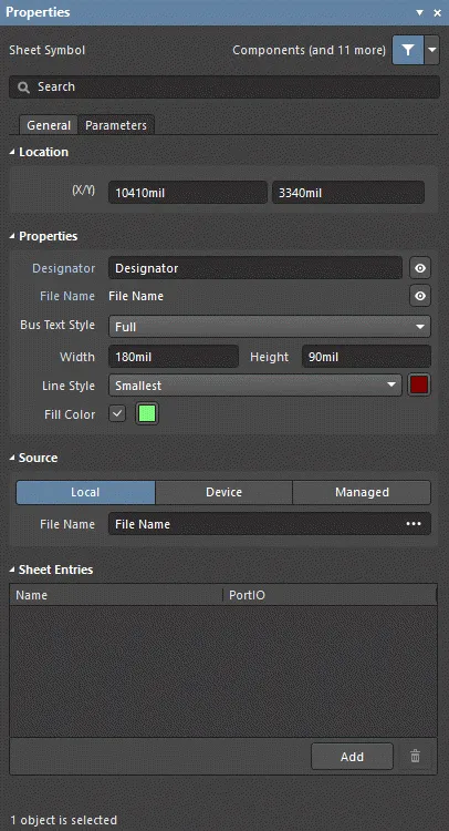
Generalタブ
位置 (プロパティ パネルのみ)
-
(X/Y)
-
X (最初のフィールド) - 現在のデザイン空間の原点に対して相対的なオブジェクトの基準点の現在のX(水平)座標。オブジェクトのX位置を変更するために編集します。値はメトリックまたはインペリアルで入力できます。現在のデフォルトと異なる単位の値を入力する場合は、単位を含めてください。
-
Y (2番目のフィールド) - 現在の原点に対して相対的なオブジェクトの基準点の現在のY(垂直)座標。オブジェクトのY位置を変更するために編集します。値はメトリックまたはインペリアルで入力できます。現在のデフォルトと異なる単位の値を入力する場合は、単位を含めてください。
プロパティ
-
Designator - シートシンボルの現在の名前。このフィールドは、シートシンボルに意味のある名前を提供し、同じ回路図シート上に配置された他のシートシンボルと区別するために使用されます。通常、名前はシンボルが表す回路図サブシートの全体的な機能を反映します。 または
または を切り替えて指定子を表示/非表示にします。
シートシンボルのインスタンス化を使用することで、同じサブシート上の複数のチャネルを単一のシートシンボルから参照できます。使用される構文は、シートシンボルの指定子フィールドでRepeatキーワードを使用し、形式は以下になります。
Repeat(SheetSymbolDesignator, FirstInstance, LastInstance)
SheetSymbolDesignatorはシートシンボルの基本名であり、FirstInstanceとLastInstanceは、インスタンス化されるチャネルの数を定義します。プロジェクトがビルドされると、コンパイラは内部コンパイルモデルをビルドする際に必要な回数だけチャネルをインスタンス化し、各チャネルの各コンポーネントを一意に識別するための注釈スキームを使用します。チャネルサブシートは複製されません。代わりに、コンパイル後、そのシート上の各チャネルに対してメインデザインウィンドウのサブシートドキュメントの下部に別のタブが表示されます。
Project OptionsダイアログのOptionsタブでNew Indexing of Sheet Symbolsオプションが有効になっている場合、繰り返されるシートシンボルの最初または最後のインデックスとして、0を含む任意の数字または数値を使用できます。最後のインデックスは常に最初のインデックスより大きくなければならず、負の数は使用できません。
特別な文字列SheetSymbolDesignatorは使用可能です。この特別な文字列は、子回路図シートに配置して、親回路図シートに配置されたシートシンボルオブジェクトの指定子を表示するために使用できます。この特別な文字列は、マルチチャネルデザインでも使用できます。子回路図シートのコンパイルされたタブを選択して、特別な文字列の変換された値を表示します。
-
File Name - シートシンボルによって参照される現在の回路図ドキュメント。 または を切り替えてファイル名を表示/非表示にします。
-
Bus Text Style - ドロップダウンからバステキストのスタイルを選択します。選択肢にはFullまたはPrefixがあります。
-
Width - 編集可能です。
-
Height - 編集可能です。
-
Line Style - ドロップダウンを使用して、使用可能な選択肢からデフォルトを選択します。カラーボックスをクリックすると、デフォルトの線の色を選択できるドロップダウンにアクセスできます。
-
Fill Color - 塗りつぶしを有効にするにはチェックします。色のボックスをクリックして、デフォルトの塗りつぶし色を選択できるドロップダウンにアクセスします。
ソース (プロパティ パネルのみ)
複数のサブシートを 1 つのシート シンボルで参照できます。File Nameフィールドの各ファイル名はセミコロンで区切ります。サブシートに配置されたオフシートコネクタを効果的に使用することで、デザインの一部を複数のシートに効果的に広げ、1枚の巨大な(フラットな)シートのように扱うことができます。ただし、オフシートコネクタは、同じシートシンボルで参照されるシートに対してのみ使用できることに注意してください。
シートエントリ (プロパティ パネルのみ)
Parametersタブ

パラメータ
シートシンボル指定子

シートシンボル指定子
概要
シートシンボル指定子は、電気設計の基本オブジェクトである非電気子オブジェクトです。これは、シートシンボルに意味のある名前を提供し、同じ回路図シート上に配置された他のシートシンボルと区別するために使用されます。通常、名前はシンボルが表す回路図のサブシートの全体的な機能を反映します。
使い方と配置
シートシンボル指定子は、親構成部品オブジェクトが配置されると自動的に配置されます。ユーザーが直接配置できるデザインオブジェクトではありません。
Designatorフィールドに加えられた変更は、PreferencesダイアログのSchematic - DefaultsページでPermanentオプションが有効にされていない限り、シートシンボル指定子オブジェクトのデフォルトプロパティを更新します。このオプションが有効にされている場合、加えられた変更は配置されているシートシンボルオブジェクトの指定子と、同じ配置セッション中に配置される後続のシートシンボルオブジェクトにのみ影響します。
グラフィカル編集
この編集方法では、設計スペース内で直接シートシンボル指定子オブジェクトを選択し、その位置をグラフィカルに変更できます。シートシンボル指定子のサイズは、PropertiesパネルのFontのサイズを変更することによってのみ調整できます。そのため、シートシンボル指定子オブジェクトが選択されているときに編集ハンドルは利用できません:

選択されたシートシンボル指定子
点線のボックス内のどこかをクリックしてから、必要に応じてシートシンボル指定子オブジェクトをドラッグして再配置します。オブジェクトはドラッグ中に回転または反転させることができます:
-
Tabキーを押して、シートシンボル指定子のプロパティをその場で変更できるPropertiesパネルにアクセスします。
-
Altキーを押して、移動の初期方向に応じて水平または垂直軸に沿った移動方向を制約します。
-
Spacebarを押してシートシンボル指定子を反時計回りに、またはShift+Spacebarを押して時計回りに回転させます。回転は90°の増分です。
-
XキーまたはYキーを押して、シートシンボル指定子をX軸またはY軸に沿ってミラーします。
PreferencesダイアログのSchematic - GeneralページでIn-Place Editingオプションが有効になっている場合、設計スペース内で直接シートシンボル指定子の名前を編集できます。指定子を選択して一度クリックして機能を呼び出し、必要に応じて新しい名前を入力してから、シートシンボル指定子フィールドからクリックして離れるかEnterキーを押して変更を適用します。
Lockedプロパティが有効になっているオブジェクトをグラフィカルに変更しようとすると、編集を進めるかどうかを確認するダイアログが表示されます。Protect Locked ObjectsオプションがPreferencesダイアログのSchematic – Graphical Editingページで有効にされ、その設計オブジェクトのLockedオプションも有効にされている場合、そのオブジェクトは選択またはグラフィカルに編集できません。ロックされたオブジェクトをクリックして選択し、リストパネルでLockedプロパティを無効にするか、Protect Locked Objectsオプションを無効にしてオブジェクトをグラフィカルに編集します。
非グラフィカル編集
以下の非グラフィカル編集方法が利用可能です。
パラメータダイアログまたはプロパティパネルを介した編集
パネルページ: シートシンボル指定子プロパティ
この編集方法は、関連するParameterダイアログとPropertiesパネルモードを使用して、シートシンボル指定子オブジェクトのプロパティを変更します。
とプロパティパネルのParameterモード(右)")
 Parameterダイアログ(左)とプロパティパネルのParameterモード(右)
配置後、Parameterダイアログは以下の方法でアクセスできます:
配置中に、Parameterモードのプロパティパネルにアクセスするには、Tabキーを押します。シートシンボル指定子が配置された後、すべてのオプションが表示されます。
配置後、Parameterモードのプロパティパネルには、以下の方法のいずれかでアクセスできます:プロパティパネルが既にアクティブな場合、シートシンボル指定子オブジェクトを選択します。
PreferencesダイアログのSchematic - Graphical EditingページでDouble Click Runs Interactive Propertiesオプションが無効(デフォルト)の場合、プリミティブをダブルクリックするか、選択したプリミティブを右クリックしてPropertiesを選択すると、ダイアログが開きます。Double Click Runs Interactive Propertiesオプションが有効になっている場合は、プロパティパネルが開きます。
ダイアログとパネルのオプションは同じですが、オプションの順序や配置が若干異なる場合があります。
シートシンボル指定子のプロパティは、配置モードに入る前にPreferencesダイアログのSchematic – Defaultsページからアクセスできます。これにより、シートシンボル指定子オブジェクトのデフォルトプロパティを変更でき、後続のシートシンボル指定子の配置時に適用されます。
複数オブジェクトの編集
現在選択されているすべてのオブジェクトで同一のプロパティ設定を変更できるプロパティパネルは、複数オブジェクトの編集をサポートしています。同じオブジェクトタイプの複数を手動で選択するか、 Find Similar ObjectsダイアログやFilterまたはListパネルを通じて選択した場合、プロパティパネルのフィールドエントリーがアスタリスク(*)として表示されていない場合、選択されたすべてのオブジェクトに対して編集できます。
リストパネルを通じた編集
パネルページ: Listパネル、SCH Filter、SCHLIB Filter
一つ以上のドキュメントの設計オブジェクトを表形式で表示できるリストパネルを使用すると、オブジェクト属性の迅速な検査と変更が可能になります。適切なフィルタリングを使用することで - 適用可能なフィルターパネルやFind Similar Objectsダイアログを使用することで - アクティブフィルターの範囲内にあるオブジェクトのみが表示され、より正確かつ効率的に複数の設計オブジェクトを対象として編集できます。
注意
-
テキストフレームはX軸またはY軸に沿って回転または反転できますが、これはテキストの向きには影響しません。
-
単純な一行テキスト注釈には、テキスト文字列オブジェクトの使用を検討してください。
-
シートシンボルのインスタンス化を使用すると、同じサブシート上の複数のチャネルを単一のシートシンボルから参照できます。使用される構文には、シートシンボル指定子フィールドでRepeatキーワードを使用し、形式は以下になります。
Repeat(SheetSymbolDesignator, FirstInstance, LastInstance)

繰り返しキーワードの使用
SheetSymbolDesignatorはシートシンボルの基本名であり、最初のインスタンスと最後のインスタンスは、インスタンス化されるチャネルの数を定義します。プロジェクトがビルドされると、コンパイラは内部コンパイルモデルを構築する際に必要な回数だけチャネルをインスタンス化し、各チャネルの各コンポーネントを一意に識別するための注釈スキームを使用します。チャネルサブシートは複製されません。代わりに、一度コンパイルされると、そのシート上の各チャネルに対してメインデザインウィンドウのサブシートドキュメントの下部に別のタブが表示されます。
Project OptionsダイアログのOptionsタブでNew Indexing of Sheet Symbolsオプションが有効になっている場合、繰り返されるシートシンボルの最初または最後のインデックスとして任意の数字または数値を使用できます。0も含まれますが、最後のインデックスは常に最初のインデックスより大きくなければならず、負の数は許可されません。
階層型設計
階層設計においては、プロジェクトにはトップシートが1つだけ含まれることを覚えておくことが重要です。他のすべてのソースドキュメントはシートシンボルによって参照されなければなりません。設計検証を行う際には、
複数のトップレベルドキュメント違反チェックを使用して、この条件が満たされていない場合にフラグを立てることができます。さらに、シートシンボルは、それが配置されているシートや、より上位のシートを参照してはならず、これが行われると構造内で解決不可能なループが発生します。
階層設計とは、設計内の木構造またはシート間の関係が表現されるものです。これはシートシンボルを用いて行われ、シートシンボルは設計階層内の下位のシートを表します。シンボルは下のシートを表し、その中のシートエントリは下のシートのポートに接続します(または接続されます)。接続はこれらのシートシンボル内のシートエントリを通じて行われ、一つのシートのポートから別のシートのポートへ直接行われるわけではありません。
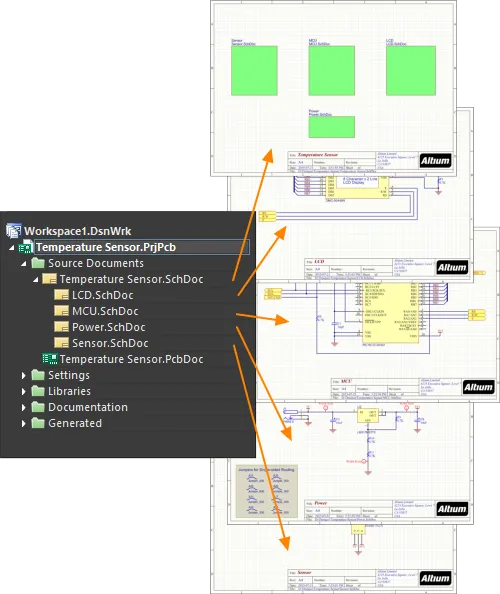
フラット設計と同様に、子シートはシートシンボル内でそのファイル名を定義することによって識別されます。階層設計では、その子シートはさらに下位レベルのシートを参照するシートシンボルを含むことができ、これによって階層内に別のレベルが作成されます。下の画像は、階層内に3レベルある階層設計を示しています。

階層設計では、木構造に示される構造は、シートシンボルによって作成される親子関係によって決定されます。
階層設計では、子シート上の信号はポートを介してシートを離れ、親シート上の対応するシートエントリに接続します。親シートには、子信号を別のシートシンボル内のシートエントリに渡す配線が含まれており、それから信号は下の画像に示されるように、2番目の子シート上の対応するポートに下がっていきます。

この親子シート構造は任意の深さに定義することができ、階層設計には任意の数のシートが存在することができます。
シート間の接続性はNet Identifier Scopeによって決定されます。これはOptionsタブのプロジェクトのオプションダイアログで設定されます。接続性の作成について詳しく知るには、接続性の作成ページを読んでください。ネット識別子スコープには自動オプションが含まれていますが、特殊な接続要件がない限り、このオプションは良い選択です。
階層設計の利点は、設計の構造を読者に示し、接続性が完全に予測可能で、常に子シートから親シート上のシートシンボルへと追跡しやすいことです。
階層設計の別の利点は、設計再利用システムの提供プラットフォームを提供することです。このシステムは、データがどのように保存されているかに応じて、ファイルベースまたはサーバーベースの2つの方法で提供されます。
-
ファイルベースのシステムはデバイスシートと呼ばれ、ライブラリのデバイスシートから既存の回路図を直接作成中の設計に配置します。デバイスシートについて詳しくは、デバイスシート記事を参照してください。
-
ワークスペースベースのシステムはマネージドシートと呼ばれ、接続されたワークスペースから既存の回路図を直接作成中の設計に配置します。マネージドシートについて詳しくは、マネージドシートページを参照してください。
Port
 配置されたポート
概要
ポートは電気設計の基本要素です。これは、複数のシート(フラットおよび階層設計の両方)を使用する設計において、一つの回路図シートと別のシート、またはシートシンボル(対応するシートエントリを介して)との間の電気的接続を行うために使用されます。ポートの名前は接続を定義します(つまり、回路図シート上のポートはプロジェクト内の他のシート上の同じ名前のポートまたはシートエントリに接続します)。
クロスリファレンス機能は、相互接続されたポートおよび相互接続されたオフシートコネクタの位置グリッド参照を識別します。これらのタイプの回路図接続オブジェクトの両方について、既存のReports » Port Cross Reference » Add To Projectコマンドは、ターゲットシート名と位置グリッド参照に基づいてクロスリファレンスパラメータを追加します。
使い方
ポートは、次の方法で回路図エディタに配置するために利用可能です:
-
メインメニューからPlace » Portをクリックします。
-
デザインスペースの上部にあるActive Barのディレクティブドロップダウンで、ポートボタン( )をクリックします。(Active Barボタンをクリックして押し続けると、他の関連コマンドにアクセスできます。コマンドを使用すると、そのセクションのActive Barの最上位項目になります。)
-
右クリックしてからPlace » Portを選択します。
配置
コマンドを起動すると、カーソルが十字線に変わり、ポート配置モードに入ります。以下の一連のアクションを実行して配置します:
-
ポートの左端を固定するためにクリックするかEnterを押します。
-
必要に応じてポートの長さを調整するためにカーソルを動かし、クリックするかEnterを押してポートの配置を完了します。
-
さらにポートを配置するか、右クリックするかEscを押して配置モードを終了します。
配置中にポートがカーソル上で浮いている間、そしてその左端が固定される前に実行できる追加のアクションは以下の通りです:
-
Tabキーを押して配置を一時停止し、ポートモードのプロパティパネルにアクセスして、その場でプロパティを変更できます。配置を再開するには、デザインスペースの一時停止ボタンオーバーレイ()をクリックします。
-
Spacebarを押してポートを反時計回りに、またはShift+Spacebarを押して時計回りに回転させます。回転は90°の増分です。
-
XキーまたはYキーを押して、X軸またはY軸に沿ってポートをミラーします。
配置中に属性を変更できます(Tabを押して関連するプロパティパネルにアクセスしますが)、PreferencesダイアログのSchematic – DefaultsページでPermanentオプションが有効にされていない限り、これらはさらなる配置のデフォルト設定になります。このオプションが有効になっている場合、変更は配置中のオブジェクトとその配置セッション中に配置される後続のオブジェクトにのみ影響します。
グラフィカル編集
この編集方法を使用すると、デザインスペースで配置されたポートオブジェクトを選択し、その長さ、高さ、または位置をグラフィカルに変更できます。
ポートオブジェクトが選択されている場合、編集ハンドルをクリックしてドラッグすることでポートのサイズを変更できます。
 選択されたポート
編集ハンドルから離れたポート上のどこかをクリックしてからドラッグすると、位置を変更できます。ドラッグ中に、ポートは回転(Spacebar/Shift+Spacebar)またはミラー(XキーまたはYキーを押してX軸またはY軸に沿ってミラー)できます。
ポートオブジェクトの名前は、以下の方法でその場で編集できます:
-
ポートを選択するために単一クリックします。
-
その場で編集モードに入るために再度単一クリックするか(またはEnterを押します)。ソフトウェアが2回の単一クリックをダブルクリックと解釈しないように、各クリックの間に十分な時間を置く必要があります(これはプロパティパネルを開きます)。
-
その場でのテキスト編集を終了するには、Enterを押すか、マウスを使用してポートから離れてクリックします。
-
ポートは、ポートの名前の長さ/高さに合わせて自動的にサイズ変更されます。
Lockedプロパティが有効になっているオブジェクトをグラフィカルに変更しようとすると、編集を続行するかどうかを確認するダイアログが表示されます。Protect Locked ObjectsオプションがPreferencesダイアログのSchematic – Graphical Editingページで有効になっており、そのデザインオブジェクトのLockedオプションも有効になっている場合、そのオブジェクトは選択またはグラフィカルに編集できません。ロックされたオブジェクトを選択してからLockedプロパティをリストパネルで無効にするか、Protect Locked Objectsオプションを無効にしてオブジェクトをグラフィカルに編集します。
非グラフィカル編集
以下の非グラフィカル編集方法が利用可能です。
ポートダイアログまたはプロパティパネルを介した編集
プロパティページ: ポートプロパティ
この編集方法は、関連するPortダイアログとPropertiesパネルモードを使用して、ポートオブジェクトのプロパティを変更します。

 左側のPortダイアログと、右側のプロパティパネルのPortモード
配置後、Portダイアログは以下の方法でアクセスできます:
配置中、は、Tabキーを押すことでアクセスできます。ポートが配置されると、すべてのオプションが表示されます。
配置後、PropertiesパネルのPortモードは、以下の方法のいずれかでアクセスできます:
PreferencesダイアログのSchematic - Graphical Editing ページのでDouble Click Runs Interactive Propertiesオプションが無効(デフォルト)の場合、プリミティブをダブルクリックするか、選択したプリミティブを右クリックしてPropertiesを選択すると、ダイアログが開きます。Double Click Runs Interactive Propertiesオプションが有効になっている場合、Propertiesパネルが開きます。
ダイアログとパネルのオプションは同じですが、オプションの順序と配置が若干異なる場合があります。
ポートプロパティは、配置モードに入る前にPreferencesダイアログのSchematic – Defaultsページからアクセスできます。これにより、ポートオブジェクトのデフォルトプロパティを変更でき、後続のポートの配置時に適用されます。
複数オブジェクトの編集
プロパティ パネルは、現在選択されているすべてのオブジェクトで同一のプロパティ設定を変更できる複数オブジェクト編集をサポートしています。同じオブジェクトタイプの複数を手動で選択するか、Find Similar Objectsダイアログ またはSCH FilterまたはSCH Listパネルを通じて選択すると、プロパティ パネルのフィールドエントリーがアスタリスク(*)として表示されない場合、選択されたすべてのオブジェクトに対して編集できます。
リストパネルを介した編集
パネルページ:Listパネル、SCH Filter
リスト パネルを使用すると、1つ以上のドキュメントの設計オブジェクトを表形式で表示し、オブジェクト属性の迅速な検査と変更を可能にします。適切なフィルタリング - 適用可能なフィルターパネル またはFind Similar Objectsダイアログを使用することで - アクティブフィルターの範囲内にあるオブジェクトのみを表示し、より正確かつ効率的に複数の設計オブジェクトをターゲットにして編集できます。
ポートアクション
配置されたポート上で右クリックすると、そのポート(または該当する場合は現在選択されているすべてのポート)に作用する以下のコマンドが利用可能なコンテキストに敏感なメニューが表示されます(Port Actionsサブメニュー上):
。
複数のポートが現在選択されている場合、コマンドはToggle Selected Ports IO Typeとして表示されます。このコマンドは選択されたすべてのポートに適用されます。
このコマンドは、Harness Typeが定義されているポートでのみ利用可能です。
注意
-
ポートとシートシンボルの関係は、プロジェクトに選択されたネット識別子スコープによって決定されます。このスコープは、Net Identifier ScopeオプションをProject Options - Optionsダイアログ(Project » Project Options)で設定することによって定義されます。
-
I/O Typeオプションは、Propertiesパネルでポートの電気的タイプを定義するために使用します。選択肢にはInput、Output、Bidirectional、またはUnspecifiedがあります。ポートのPort DirectionオプションがPreferencesダイアログのSchematic – Generalページで有効になっている場合、ポートは自動的にI/Oタイプを表示します。
-
ポート名の上にバーを含める(否定する)には、以下の方法のいずれかを使用します:
-
デフォルト設定では、ポート名はネットの命名に使用されません。ポートをネットの命名に使用する場合は、Options for ProjectダイアログのOptionsタブでAllow Ports to Name Netsオプションを有効にします。このオプションが無効の場合、そのネットにネットラベルや電源オブジェクトが関連付けられていない、または階層設計でAllow Sheet Entries to Name Netsオプションが有効になっていない場合、システム生成のネット名が使用されます。 ネットの命名方法についてもっと学びましょう。
-
ポートは、ポート名の長さ/高さに合わせて自動的にサイズ変更されます。テキストの入力方法に関わらず、自動サイズ調整は機能します(ポートモードのPropertiesパネルまたは設計スペース内での直接編集を通じて)。
-
ポートがシグナルハーネスに接続されると、ポートはハーネスオブジェクトになります。デフォルトでは、ポートはシグナルハーネスの色に合わせて色が変わります。
-
ポートがシグナルハーネスによってハーネスコネクタに接続されている場合、PropertiesパネルのHarness Typeには、ハーネスコネクタのハーネスタイプが自動的に入力されます。ポートがシグナル ハーネスによってシート エントリに接続され、シート エントリにハーネス タイプが宣言されている場合、ポートはハーネス オブジェクトになり、シグナル ハーネスの色に変わります。ポートをハーネス コネクタまたはシート エントリから離すと、ポートはデフォルトの色に戻ります。
-
デフォルトでは、ポートのNameに使用されるフォントは、ワークスペース内でオブジェクトが選択されていないときのPropertiesパネルのDocument Optionsモードで設定されたグローバルドキュメントレベルのフォントに従います。これは、PropertiesパネルのFont設定を使用して個々のポートレベルで上書きでき、必要に応じてポートのテキスト表示を完全に制御できます。
-
OrCADデザインがインポートウィザードを使用してインポートされる場合、生成された回路図ドキュメントにカスタムポートコネクタがサポートされます。そのようなポートは元のデザインと同じグラフィックスを持ちます。OrCADからデザインをインポートするについてもっと学びましょう。
-
xDX Designerデザインがインポートウィザードを使用してインポートされる場合、生成された回路図ドキュメントにカスタムポートがサポートされます。そのようなポートは元のデザインと同じグラフィックスを持ちます。xDX DesignerまたはDxDesignerからデザインをインポートするについてもっと学びましょう。
ポートのプロパティ
回路図エディタオブジェクトのプロパティは、配置されたオブジェクトの視覚スタイル、内容、および動作を指定する定義可能なオプションです。各種オブジェクトのプロパティ設定は、2つの異なる方法で定義されます:

Double Click Runs Interactive PropertiesオプションがPreferencesダイアログのSchematic - Graphical Editingページで無効になっている(デフォルト)場合、プリミティブをダブルクリックするか、選択したプリミティブを右クリックしてPropertiesを選択すると、ダイアログが開きます。Double Click Runs Interactive Propertiesオプションが有効になっている場合、Propertiesパネルが開きます。
ダイアログとパネルのオプションは同じですが、オプションの順序と配置は若干異なる場合があります。
以下のプロパティリストでは、設定ダイアログのデフォルト設定として利用できないオプションは「Propertiesパネルのみ」と記載されています。
Generalタブ
位置(プロパティパネルのみ)
-
(X/Y)
-
X(最初のフィールド) - 現在のデザインスペース原点に対するオブジェクトの基準点の現在のX(水平)座標です。オブジェクトのX位置を変更するために編集します。値はメートル法またはインペリアルで入力できます。現在のデフォルトと異なる単位の値を入力する場合は、単位を含めてください。
-
Y(2番目のフィールド) - 現在の原点に対するオブジェクトの基準点の現在のY(垂直)座標です。オブジェクトのY位置を変更するために編集します。値はメートル法またはインペリアルで入力できます。現在のデフォルトと異なる単位の値を入力する場合は、単位を含めてください。
プロパティ
この設定は回路の接続性には影響しませんが、互換性のないポート方向を検出するように設定された電気ルールチェックの実行時に考慮されます。
-
Harness Type - ドロップダウンからハーネスのタイプを選択してください。
-
Cross Ref - このフィールドには、ポートに適用されるクロスリファレンス値が表示されます。
-
Width- 編集可能です。
-
Width- 編集可能です。
-
Font- 希望のフォント、フォントサイズ、色、太字、イタリックなどの属性を選択するためのコントロールを使用してください。
-
Alignment- 希望の配置設定をクリックしてください。
-
Border - ドロップダウンを使用して、利用可能な選択肢からデフォルトを選択してください。デフォルトの色を選択できるドロップダウンにアクセスするために、色付きのボックスをクリックしてください。
-
Fill- デフォルトの色を選択できるドロップダウンにアクセスするために、色のボックスをクリックしてください。
一般 (ネット)
ポートに割り当てられたネットのプロパティを表示します。必要に応じて更新してください。
Power NetおよびHigh Speedフィールドは、オブジェクトにディレクティブが追加された後に利用可能になります。
パラメータ (ネット)
Addボタンは、オブジェクトにディレクティブが追加された後に利用可能になります。
Parametersタブ

パラメータ
この領域を使用して、現在選択されているポートオブジェクトに添付されたパラメータを管理します。
-
Grid - ポートに現在定義されているパラメータのNameとValueをリストします。必要に応じてフィールドを直接編集できます。およびを使用してパラメータを表示/非表示にします。選択したパラメータをロック/アンロックするには、ロックアイコンを使用してください。
-
Font Settings - フォントを定義するためのメニューを開くためにクリックしてください。
-
Other - 追加のオプションを変更するためのドロップダウンを開くためにクリックしてください:
-
Show Parameter Name - パラメータの名前を表示するために有効にしてください。
-
Allow Synchronization with Database - データベースと同期するために有効にしてください。
-
X/Y - XおよびYの座標を入力してください。
-
Rotation - ドロップダウンを使用して回転を選択してください。
-
Autoposition - 自動位置決めを有効にするためにチェックしてください。
-
Add - パラメータを追加するためにクリックしてください。テーブルから選択したエントリを削除するために を使用してください。
クロスリファレンス機能は、相互接続されたポートとオフシートコネクタの位置グリッド参照を識別します。両方のタイプの回路図接続オブジェクトについて、既存のReports » Port Cross Reference » Add To Projectコマンドは、ターゲットシート名と位置グリッド参照に基づいてクロスリファレンスパラメータを追加します。
シートエントリ

配置されたシートエントリ
概要
シートエントリは、シートシンボル内に属する電気設計の基本要素です。シンボルの入出力ポートを指定するために、シートシンボル内に配置されます。シートエントリは、シンボルが表すソース回路図サブシート内に配置されたポートに対応します。
使い方
シートエントリは、以下の方法でのみ回路図エディタで配置が可能です:
-
メインメニューからPlace » Sheet Entryを選択します。
-
デザインスペースの上部にあるActive Barのグラフィックオブジェクトドロップダウンで、Sheet Entryボタン(  )をクリックします。(Active Barのボタンをクリックして押し続けると、他の関連コマンドにアクセスできます。コマンドを使用すると、そのセクションのActive Barの最上位アイテムになります。)
-
デザインスペースで右クリックし、コンテキストメニューからPlace » Sheet Entryを選択します。
-
Wiringツールバーの ボタンをクリックします。
配置
コマンドを起動すると、カーソルが十字線に変わり、シートエントリの配置モードに入ります。配置は、以下の一連のアクションを実行することで行われます:
-
カーソルに付いたシートエントリをシート上の配置済みシートシンボルの上に移動します。
-
シートエントリの位置をシートシンボルの端に対して調整し、クリックするかEnterを押して、必要な端にシートエントリを固定し、配置を完了します。
-
さらにシートエントリを配置するか、右クリックするかEscを押して配置モードを終了します。
シートエントリの色付けは、配置を補助します。シートシンボルの外側では、エントリはグレー表示され配置できないようになります。シートシンボルの上にあるとき、エントリは青く表示され、その位置に配置できることを示します。配置されると、エントリはPropertiesパネルのFill Colorプロパティで定義された本来の色に戻ります。
配置中に属性を変更できます(Tabを押してPropertiesパネルにアクセス)。ただし、Preferencesダイアログのchematic – Defaults pageでPermanentオプションがS有効になっていない限り、これらはさらなる配置のデフォルト設定になります。このオプションが有効になっている場合、変更は配置中のオブジェクトとその配置セッション中に配置される後続のオブジェクトにのみ影響します。
グラフィカル編集
この編集方法では、デザインスペースで配置されたシートエントリオブジェクトを直接選択し、その位置をグラフィカルに変更できます。
シートエントリは、PropertiesパネルでI/O Typeを変更することによってのみ、その形状に関して調整できます。そのため、シートエントリオブジェクトが選択されているときは編集ハンドルは利用できません。

選択されたシートエントリ
-
必要に応じて、親シートシンボル内でシートエントリをクリックしてドラッグし、再配置します。
-
Ctrlを押しながらクリックしてドラッグすると、シートエントリを現在のシートシンボルからシート上の別のシートシンボルに移動できます。ソースシートシンボルの境界をシートエントリがクリアすると、Ctrlキーを離すことができます。
-
シートシンボルの境界外にシートエントリをクリックしてドラッグすると、シートシンボルが自動的にリサイズされ、エントリの新しい位置を収容します。
複数のシートエントリを同時に移動するには、Ctrlを押しながら選択するエントリの1つをクリックし、その後、全体の選択をドラッグします。ドラッグを開始すると、Ctrlキーを離すことができます。複数のオブジェクトを選択するにはShiftを押しながら保持します。
PreferencesダイアログのSchematic – General pageでEnable In-Place Editingオプションが有効になっている場合、デザインスペースで直接シートエントリの名前を編集できます。シートエントリオブジェクトを選択し、機能を呼び出すために一度クリックします。必要に応じて新しい名前を入力し、シートエントリオブジェクトからクリックして離れるか、Enterを押して変更を適用します。
オブジェクトのLockedプロパティが有効になっている場合、グラフィカルに修正しようとすると、編集を続行するかどうかを確認するダイアログが表示されます。もしPreferencesダイアログのSchematic – Graphical EditingページでProtect Locked Objectsオプションが有効になっており、その設計オブジェクトのLockedオプションも有効になっている場合、そのオブジェクトは選択またはグラフィカルに編集することができません。ロックされたオブジェクトをクリックして選択し、Lockedプロパティをリストパネルで無効にするか、Protect Locked Objectsオプションを無効にしてオブジェクトをグラフィカルに編集します。
非グラフィカル編集
以下の非グラフィカル編集方法が利用可能です。
シートエントリダイアログまたはプロパティパネルを介した編集
プロパティページ:シートエントリプロパティ
この編集方法は、関連するSheet EntryダイアログとPropertiesパネルモードを使用して、シートエントリオブジェクトのプロパティを変更します。
のSheet EntryモードのとSheet Entryダイアログ(2番目の画像)")

Propertiesパネル(最初の画像)のSheet EntryモードのとSheet Entryダイアログ(2番目の画像)
配置後、Sheet Entryダイアログは次の方法でアクセスできます:
-
配置されたシートエントリオブジェクトをダブルクリックします。
-
シートエントリオブジェクトの上にカーソルを置き、右クリックしてからコンテキストメニューからPropertiesを選択します。
配置中、Propertiesパネルのシートエントリモードには、Tabキーを押すことでアクセスできます。シートエントリが配置されると、すべてのオプションが表示されます。
配置後、Propertiesパネルのシートエントリモードには、次の方法のいずれかでアクセスできます:
Double Click Runs Interactive PropertiesオプションがPreferencesダイアログのSchematic – Graphical Editingページで有効になっている(デフォルト)場合、プリミティブをダブルクリックするか、選択したプリミティブを右クリックしてPropertiesを選択すると、Propertiesパネルが開きます。Double Click Runs Interactive Propertiesオプションが無効になっている場合、ダイアログが開きます。
ダイアログとパネルのオプションは同じですが、オプションの順序と配置は若干異なる場合があります。
シートエントリプロパティは、配置モードに入る前にPreferencesダイアログのSchematic – Defaultsページからアクセスできます。これにより、シートエントリオブジェクトのデフォルトプロパティを変更でき、後続のシートエントリの配置時に適用されます。
複数オブジェクトの編集
プロパティパネルは、現在選択されているすべてのオブジェクトで同一のプロパティ設定を変更できる複数オブジェクト編集をサポートしています。Find Similar ObjectsダイアログやFilter、Listパネルを介して、または手動で同じオブジェクトタイプの複数を選択した場合、Propertiesパネルのフィールドエントリがアスタリスク(*)として表示されていない場合、選択されたすべてのオブジェクトに対して編集できます。
リストパネルを介した編集
パネルページ: Listパネル、SCHフィルター
リストパネルを使用すると、1つ以上のドキュメントからデザインオブジェクトを表形式で表示できるため、オブジェクト属性をすばやく確認および変更できます。適切なフィルタリングと組み合わせて使用 – 適切なフィルターパネルまたはFind Similar Objectsダイアログを使用して、アクティブなフィルターの範囲に該当するオブジェクトのみを表示できるようになり、複数のデザインオブジェクトをより正確かつ効率的にターゲット化して編集することができます。
右クリックシートエントリアクション
配置されたシートエントリ上で右クリックすると、コンテキストに応じたメニューが表示され、以下のコマンドが利用可能です(Sheet Entry Actionsサブメニューにて)。これらのコマンドは、そのシートエントリ(または適用可能な場合は現在選択されているすべてのシートエントリ)に作用します:
-
Toggle Selected Sheet Entries IO Type – このコマンドを使用して、シートエントリのI/Oタイプを切り替えます。これは、Toggle Selected Sheet Entries IO Typeをクリックして、Edit » MoveメインメニューやActive Barからも利用できます。

シートエントリのIOタイプを切り替える例
実際の変更は、現在のI/Oタイプによって以下のようになります:
-
Swap Selected Sheet Entries Side – シートエントリを親シートシンボルの直接反対側に移動するために使用します。交換によってシートエントリのI/Oタイプは変更されません。これは、メインメニューとActive BarからEdit » Move » Swap Selected Sheet Entries Sideをクリックしても利用できます。

シートエントリの側面を交換する例。
注意
-
シートエントリがシグナルハーネスに接続されると、シートエントリはハーネスオブジェクトになります。デフォルトでは、シートエントリはシグナルハーネスの色と一致する色に変わります。PreferencesダイアログのSchematic – Graphical EditingページでSheet Entries and Ports use Harness Colorオプションを無効にして、シートエントリの色を指定するか、デフォルトの色を使用します。
-
シートエントリがシグナルハーネスによってハーネスコネクタに接続されると、Harness TypeがPropertiesパネルで自動的にハーネスコネクタのハーネスタイプに設定されます。シートエントリがシグナルハーネスによってポートに接続され、ポートにHarness Typeが宣言されている場合、シートエントリはハーネスオブジェクトになり、シグナルハーネスの色に変わります。シートエントリをハーネスコネクタから移動し、Harness Typeフィールドが入力されていない場合、シートエントリはデフォルトの色に戻ります。
-
シートエントリ名の上にバーを含める(否定する)必要がある場合は、以下の方法のいずれかを使用します:
-
ピン名の各文字の後にバックスラッシュ文字を含めます(例:E\N\A\B\L\E\)。
-
Single '\' NegationオプションをPreferencesダイアログのSchematic – Graphical Editingページで有効にし、ピン名の先頭に1つのバックスラッシュ文字を含めます(例:\ENABLE)。
-
デフォルト設定では、シートエントリ名がネットの名前付けに使用されます。この動作は、Allow Sheet Entries to Name Netsオプションによって制御されます。これは、Options for ProjectダイアログのOptionsタブで設定します。オプションが無効になっている場合、そのネットにネットラベルや電源オブジェクトが関連付けられていない、または階層設計でAllow Ports to Name Netsオプションが有効になっていない場合、システム生成のネット名が使用されます。ネットの名前付け方法についてもっと学びましょう。
-
同じシートシンボルから複数のチャネルをインスタンス化する場合、特定の信号が繰り返され、それぞれのインスタンス化されたチャネルに個別に送信されます。シートエントリに関しては、シートエントリの名前にRepeatキーワードを使用することで、信号が繰り返されます(例: Repeat(Headphone))。その後、シートエントリはバスに配線され、バスが個々の信号をそれぞれのインスタンス化された宛先に運びます。
-
シート エントリから子シートの対応するポートにすばやくジャンプするには、シート エントリ オブジェクトをCtrl+クリックします。回路図 PDF 出力で、シート エントリをクリックして、子回路図 ページ上のポートに移動します。
シートエントリのプロパティ
回路図エディタのオブジェクトプロパティは、配置されたオブジェクトの視覚スタイル、内容、および動作を指定する定義可能なオプションです。各種類のオブジェクトのプロパティ設定は、2つの異なる方法で定義されます:
-
Pre-placement settings – 多くの シートエントリオブジェクトプロパティ、または論理的に事前に定義可能なものは、 Preferencesダイアログ (デザインスペースの右上にあるボタンからアクセス)のSchematic – Defaultsページ の編集可能なデフォルト設定として利用可能です。オブジェクトをPrimitive Listで選択すると、そのオプションが右側に表示されます。

-
Post-placement settings – すべての シートエントリ オブジェクトプロパティは、デザインスペースで配置されたシートエントリが選択されたときに、 PropertiesパネルおよびSheet Entryダイアログで編集可能です。
Double Click Runs Interactive PropertiesオプションがPreferencesダイアログのSchematic – Graphical Editingページで有効にされている場合(デフォルト)、プリミティブをダブルクリックするか、選択したプリミティブを右クリックしてPropertiesを選択すると、Propertiesパネルが開きます。Double Click Runs Interactive Propertiesオプションが無効にされている場合は、ダイアログが開きます。
パネルとダイアログのオプションは同じですが、オプションの順序や配置が若干異なる場合があります。
プロパティ
-
Cross Ref – このフィールドは、シートエントリに適用されるクロスリファレンス値を表示します。 または  アイコンを使用して、デザインスペースでシートエントリのクロスリファレンス値の表示を有効/無効にします。
-
Font – フォント、フォントサイズ、フォントカラーを選択し、太字、イタリック、下線などの特別な特性をフォントに追加するためのコントロールを使用します。
-
Kind – ドロップダウンからテキストの種類を選択します。
-
Border Color – 色ボックスをクリックして、境界色を選択するためのコントロールにアクセスします。
-
Fill Color – カラーボックスをクリックして、境界線の色を選択するコントロールにアクセスします。
パラメータ(ネット)
クロスリファレンスの追加
プロジェクトにクロスリファレンスを追加することで、プロジェクト内の回路図シート間のネットの接続フローを簡単に追跡できます。回路図エディタは、クロスリファレンスの自動作成および更新をサポートしています。
Automatic Cross ReferencesオプションをGeneral領域で有効にし、Project OptionsダイアログのOptionsタブのCross References領域でオプションを設定します。アクティブプロジェクトのクロスリファレンスの特定のスタイルを設定するか、Follow Cross References settings in Preferencesオプションを有効にして、PreferencesダイアログのSchematic – GeneralページのPort Cross References領域でオプションを継承します。ここから、クロスリファレンスが表示されるオブジェクト(ポート、オフシートコネクタ、シートエントリ)も選択できます。
Project OptionsダイアログのOptionsタブには、メインメニューからReports » Automatic Cross References Settingsコマンドを選択するか、デザインスペースを右クリックしてコンテキストメニューからSheet Actions » Automatic Cross References Settingsコマンドを選択することで、すばやくアクセスできます。

アクティブプロジェクトの自動クロスリファレンスをProject OptionsダイアログのOptionsタブで設定します。
クロスリファレンスは、設定されたスタイルで選択されたオブジェクトの隣の回路図に表示されます。クロスリファレンスの値は、選択されたオブジェクトのクロスリファレンスの表示を切り替えることができるPropertiesパネルにも表示されます。

クロスリファレンスは回路図上で、および選択されたオブジェクトについてPropertiesパネルで調査できます。ここにポートのクロスリファレンスの例が示されています。
クロスリファレンスは、回路図PDF出力でもサポートされています。オブジェクトが複数の接続オブジェクト(例えば、ポートが親回路図シートのシートエントリと他のシートのポートに接続されている)に関連している場合、PDF出力でオブジェクトをクリックすると、接続オブジェクトが存在するシートのリストが表示されます。リスト項目を選択して対応するページを開きます。オブジェクトが単一の接続オブジェクトに関連している場合、オブジェクトをクリックするとすぐに対応するページが開きます。

回路図PDF出力では、ポップアップメニューを使用して複数の接続オブジェクトを簡単にナビゲートできます。
マルチシート設計の作成
プロジェクトに2枚目の回路図シートを追加すると、マルチシート設計が作成されます。トップシートなしでフラットデザインを作成する予定の場合は、プロジェクトに回路図シートを追加し続けるだけです(Projectsパネルのプロジェクトのエントリを右クリックして、コンテキストメニューからAdd New to Project » Schematicコマンドを選択)、そしてネット識別子のスコープが正しく設定されていることを確認します。
下位レベルのシートを参照するためにシートシンボルを使用したい場合は、シートシンボルを配置して手動で編集して下位レベルのシートを正しく参照するか、以下に説明するように様々な組み込みコマンドを使用できます。
子シートの参照
シートシンボルのFilenameプロパティが下位レベルのシートを参照します。このフィールドには、そのファイルの場所へのパスではなく、回路図ファイル名のみを含めるべきです(この場所データは実際にはプロジェクトファイルに格納されています)。

Filenameプロパティ子回路図が親回路図と同じフォルダに保存される必要はありません。
ファイルが親の保存フォルダより下のフォルダに保存されている場合は、相対ファイル参照が使用されます。ファイルが別の場所に保存されている場合は、絶対ファイル参照が使用されます。このようなプロジェクトでファイルを移動する際は注意するか、プロジェクトパッケージャを使用してファイルをZIP化し、プロジェクトをZIP化する際にファイルパスを解決します。
マルチシート設計のナビゲーション
回路図エディタは、マルチシート設計内のドキュメントや関連オブジェクト間を移動するためのツールを提供します。
Tools » Up/Down Hierarchyコマンドは、現在のドキュメントから設計階層の次のレベルへ、上または下へフォーカスを移動するために使用されます。このコマンドを起動すると、カーソルが十字線に変わり、ナビゲーションポイントを選択するように求められます。シートエントリをクリックすると、サブシート上の対応するポートが表示され、シートシンボルをクリックすると、サブシート全体が表示されます。階層を上にナビゲートするには、親シート上の対応するシートエントリを表示するためにポートをクリックします。
シートエントリまたはポートがバスに接続されている場合、最初のクリックでメニューが表示され、そこからバス全体またはバス内の個別の信号を選択できます。シートエントリまたはポートからの対応する配線が強調表示されます。元のシートエントリまたはポートを2回クリックすると、それぞれ下の回路図シート上の対応するポート、または上のシート上のシートエントリが表示されます。
カーソルの下にあるシートシンボルによって参照される子シートを開くには、配置されたシートシンボルの上で右クリックし、コンテキストメニューからSheet Symbol Actions » Open SubSheet <SchematicDocumentName>コマンドを選択します。このコマンドを起動すると、シンボルによって参照される回路図ドキュメントが開かれ(まだ開かれていない場合)、メインの設計ウィンドウでアクティブなドキュメントになります。
関連オブジェクトに対して自動クロスリファレンスが有効になっている場合、オブジェクトの右クリックPort Actions、Sheet Entry ActionsおよびOff Sheet Actions(フラットデザイン用)サブメニューからJump Toコマンドを使用して、ポート、シートエントリ、およびシート外コネクタ間をナビゲートすることもできます。たとえば、Automatic Cross Referencesオプションが有効になっており、 Options for ProjectダイアログOptionsタブのPortsオプションでSheet Entry & Ports設定オプションが選択されている場合、ポート上で右クリックして必要なPort Actions » Jump to Port <PortName> on <SchematicDocumentName>またはPort Actions » Jump to Sheet Entry <PortName> on <SchematicDocumentName>コマンドをコンテキストメニューから選択すると、指定されたポートまたはシートエントリのソースドキュメントがアクティブなドキュメントになり、カーソルがポートまたはシートエントリの上に配置されます。ターゲットドキュメント上の同じ名前のすべてのポート(および接続された配線)が強調表示されます。

設計内のどこかの一致するオブジェクトにジャンプするには、Jump toコマンドを使用します。
-
オブジェクト間をナビゲートすると、対応するオブジェクトが設計スペースで強調表示されます。視覚表示は、PreferencesダイアログのSystem - Navigationページで定義されたHighlight Methods(暗くする、ズーム、選択)に従います。
-
階層は、Ctrlを押しながらポート、シートエントリ、またはシートシンボルの上をダブルクリックすることで直接ナビゲートすることもできます。
-
階層は、NavigatorパネルのInteractive Navigation機能を使用してナビゲートすることもできます。
階層の作成
このソフトウェアには、マルチドキュメントの階層構造を構築するための多数のコマンドが含まれています。使用するコマンドは、個人の設計方法論に依存します - これは大まかにトップダウンまたはボトムアップとして分類されます。これらのコマンドは、シートエントリの追加、新しい回路図シートの作成、ポートの配置など、プロセスに必要なすべての要素を処理するため、階層を手動で作成するよりも効率的です。
このコマンドを使用して、トップダウン方式で階層を構築します:
このコマンドを使用して、ボトムアップ方式で階層を構築します:
このコマンドを使用して、設計内の回路配置を再編成します:
なぜ一つのシートから別のシートへのコンポーネントの移動に専用のコマンドが提供されているのか疑問に思うかもしれませんが、これは標準のカット&コピー コマンドが各コンポーネントの一意識別子を自動的にリセットするためです。UIDは、回路図コンポーネントをPCBコンポーネントに結びつけます。回路図コンポーネントのUIDがリセットされている場合、設計が同期されるとき(Design » Updateコマンドが使用されたとき)に、デザイン指定子を介して一致を試みるように求められます。必要に応じて、PCBエディタ内のProject » Component Linksコマンドを使用してUIDを再同期できます。
►設計同期
設計の再構築
主要記事: デザインリファクタリング
デザインのプロセスはしばしば非構造的で有機的であり、デザイナーは同時にデザインの複数の部分に対してアイデアを練っているかもしれません。アイデアが進化するにつれてセクションをキャプチャします。それは、始めは整然と配置された回路図が、混雑して整理が悪くなる可能性があることを意味します。回路図デザインを再編成するためにカット、コピー、ペーストを使用できますが、これが常に最良のアプローチではありません。
なぜカットやコピーを使わないのか?それは、各コンポーネントが配置されるときに一意の識別子が割り当てられ、この識別子はコンポーネントがカット/コピーされてペーストされるたびに自動的にリセットされるからです。このUID管理は、デザイン内で使用される各UIDのインスタンスが1つだけであることを保証するために行われます。なぜなら、それは回路図コンポーネントをPCBコンポーネントにリンクする鍵となるフィールドだからです。デザインがPCBエディタに転送されていない場合は、カット/コピー/ペーストのアプローチで問題ありませんが、転送されている場合は、リファクタリングツールを使用する方が良いでしょう。
サブ回路を別のシートに移動する
回路のセクションを一つのシートから別のシートに移動する最も簡単な方法は、それを選択してからEdit » Refactor » Move Selected Sub-circuit to Different Sheetコマンドを実行することです。Choose Destination Documentダイアログが開き、ターゲットシートを選択してOKをクリックすると、そのシートが表示され、サブ回路がカーソル上に浮かんで配置の準備ができます。

プロジェクト内の異なるシートに回路の選択されたセクションを簡単に移動できます。Move Selected Subcircuit to Different Sheetコマンドを使用します。
►デザインリファクタリングについてもっと学ぶ。
ポートとシートエントリの同期
デザインの再構成の一環としてコンポーネントと配線を移動した場合、子シートをそのシートシンボルに同期させる必要があるかもしれません。つまり、各ポートが対応するシートエントリと一致している必要があります。これはSynchronize Sheet Entries and Portsコマンドを使用して行います。これには:
-
A specific Sheet Symbol - シートシンボルを右クリックしてコンテキストメニューを表示し、Sheet Symbol Actions » Synchronize Sheet Entries and Portsコマンドを選択して、カーソル下のシートシンボルのみを分析します。
-
All Sheet Symbols in the design - Design » Synchronize Sheet Entries and Portsコマンドを選択して、デザイン全体のすべてのシートシンボルを分析します。ダイアログには、デザイン内の各シートシンボルに対応するタブが含まれ、Only Show unmatched sheet symbolsオプションがダイアログの下部にあります。
これらのコマンドの両方で、Synchronize Ports to Sheet Entriesダイアログが開きます。これは、既に一致しているポート/シートエントリをダイアログの右側にリストし、一致していないポートとシートエントリを左側の2列にリストします。シートシンボルがその参照された子シートと「同期している」とは、そのシートエントリがそのサブシート上の対応するポートと名前とI/Oタイプの両方で一致している場合を指します。

Synchronize Ports to Sheet Entriesダイアログは、シートエントリが子シート上のポートと一致することを保証するために使用されます。2つのタブに注意してください。これは、このデザインにシートエントリ/ポートの不一致がある2つのシートシンボルがあることを意味します。
シートエントリとポートの同期ダイアログのオプションとコントロール
-
Unmatched Sheet Entries - この領域は、シートシンボルに関連付けられた現在一致していないすべてのシートエントリのリストを表示します。シートシンボルの指定子が領域のヘッダーとして表示されます。各シートエントリは、その名前、I/Oタイプ、およびハーネスタイプの観点からリストされます。
-
Add Ports - このボタンをクリックすると、領域で現在選択されている各シートエントリに対して、同じ名前、I/Oタイプ、およびハーネスタイプでポートが自動的に作成されます。ポートがカーソルに浮かんだ状態で子シートに移動し、初期配置の準備が整います。クリックまたはEnterキーを押してポートを配置します。Synchronizeダイアログが再表示され、シートエントリとポートのペアリングが自動的にLinks領域に入力されます。
-
Delete Sheet Entries - このボタンをクリックすると、現在選択されているシートエントリが削除されます。エントリは領域から削除され、親シートシンボルからも削除されます。
-
Unmatched Ports - このダイアログの領域は、シートシンボルによって参照される回路図シート上の現在一致していないすべてのポートのリストを表示します。ドキュメント名が領域のヘッダーとして表示されます。各ポートエントリは、その名前、I/Oタイプ、およびハーネスタイプの観点からリストされます。
-
Add Sheet Entries - このボタンをクリックすると、領域で現在選択されている各ポートに対して、同じ名前、I/Oタイプ、およびハーネスタイプでシートエントリが自動的に作成されます。シートエントリがカーソルに浮かんだ状態でシートシンボルに移動し、初期配置の準備が整います。クリックまたはEnterキーを押してシートエントリを配置します。同期ダイアログが再表示され、シートエントリとポートのペアリングが自動的にLinks領域に入力されます。
-
Delete Ports - このボタンをクリックすると、現在選択されているポートが削除されます。ポートは領域から削除され、参照されている子シートからも削除されます。
-
Links - このダイアログの領域は、現在リンクされている(または一致している)シートエントリとポートのペアリングのリストを表示します。各エントリは、シートエントリとポートの両方で使用される名前、I/Oタイプ、およびハーネスタイプを反映しています。
複数のエントリを選択するために標準のマルチセレクト技術(Ctrl+クリック、Shift+クリック、クリック+ドラッグ)を使用します。
ボタン
以下のボタンは、同期プロセスを手動で制御するために使用されます:
-
 - Unmatched Sheet Entries領域の選択されたシートエントリとUnmatched Ports領域の選択されたポートエントリを、シートエントリで定義された名前、I/Oタイプ、およびハーネスタイプを使用してリンクするためにこのボタンをクリックします。ポートは名前が変更されるか、またはI/Oタイプやハーネスタイプがそれに応じて変更されます。
-
 - Unmatched Sheet Entries領域の選択されたポートエントリとUnmatched Ports領域の選択されたシートエントリを、ポートで定義された名前、I/Oタイプ、およびハーネスタイプを使用してリンクするためにこのボタンをクリックします。シートエントリは名前が変更されるか、またはI/Oタイプやハーネスタイプがそれに応じて変更されます。
-
 - ダイアログのLinks領域で現在選択されているシートエントリとポートの関連付けを解除するためにこのボタンをクリックします。個々のエンティティは、それぞれの一致しない領域にリストされます。
追加のコントロール
ダイアログの左側に表示される不一致に焦点を当て、最初の列のシートエントリを選択し、次に第二列の正しいポートを選択し、次にダイアログの中央にある必要なボタンをクリックして、それボタンの機能は以下の通りです:
左側の列で複数のシートエントリが選択されている場合、ソフトウェアは各シートエントリを第二列の隣接するポートと同期させます。隣接するポート(またはシートエントリ)がない場合、新しいものが作成されます。

