テキストオブジェクトは、回路図に追加情報を加えたり、ユーザーノートを配置したり、回路図のテンプレートをレイアウトするために使用できる非電気的な基本要素です。これらのテキストオブジェクトは、回路図シート上にユーザー定義テキストとして配置することも、設計やシステム情報のプレースホルダーとして機能することもできます。これを「特別な文字列」と呼びます。
テキスト文字列、テキストフレーム、およびノート
Altium Designerは、テキスト文字列、テキストフレーム、およびノートをサポートしています。
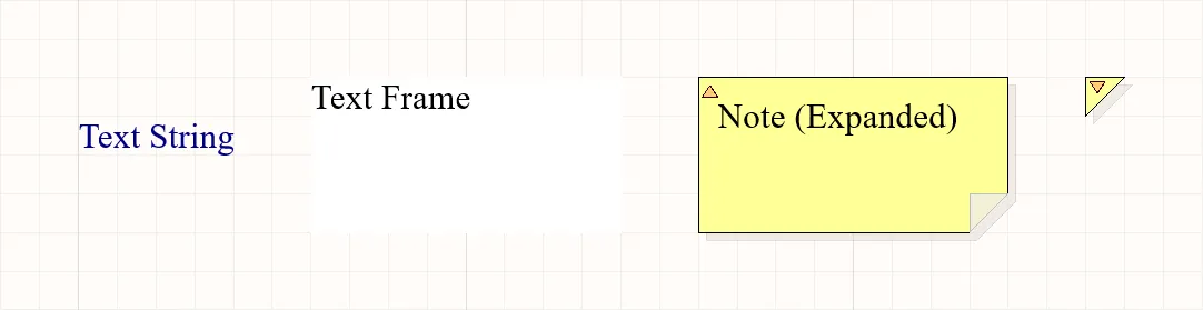
配置されたテキスト文字列、テキストフレーム、およびノート(展開モードと折りたたみモードの両方)。
| テキストオブジェクト |
説明 |
| テキスト文字列 |
回路図シート上に配置できる1行の自由テキストです。セクション見出し、リビジョン履歴、タイミング情報、またはその他の記述的または指示的テキストに使用できます。回路図エディタと回路図シンボルエディタの両方で配置が可能です。 |
| テキストフレーム |
回路図上のエリアにテキスト情報を含むために使用されます。フレームは、複数行のテキストを含むことができ、テキストをフレームの境界内に保つために自動的に折り返しとクリップを行うことができる、サイズ変更可能な長方形のエリアです。回路図エディタと回路図シンボルエディタの両方で配置が可能です。 |
| ノート |
プログラムのソースコードにコメントを追加するのと同様に、回路図内の特定のエリアに情報または指示テキストを追加するために使用されます。ノートは、複数行のテキストを含むことができ、テキストをノートの境界内に保つために自動的に折り返しとクリップを行うことができる、サイズ変更可能な長方形のエリアです。テキストフレームとは異なり、ノートは展開モードまたは折りたたみモードのいずれかで表示できます。回路図シンボルエディタでの配置が可能です。
ワークスペースプロジェクトの場合、Altium Designerは設計協力プロセスを強化するためのドキュメントコメントシステムをサポートしていることに注意してください。 ドキュメントコメントページを参照して、詳細を学んでください。
|
テキストオブジェクトの配置
テキスト文字列、テキストフレーム、およびノートは、それぞれのエディターのメインメニューのPlace » Text String、Place » Text Frame、およびPlace » Noteコマンドを使用して配置できます。
コマンドを起動すると、カーソルが十字線に変わり、テキストオブジェクト配置モードに入ります。
-
テキスト文字列の場合、カーソル上に浮かび上がります。オブジェクトを位置づけてから、クリックまたはEnterを押して配置を行います。
-
テキストフレームまたはノートの場合、カーソルを位置づけてからクリックまたはEnterを押し、オブジェクトの最初の角を固定します。カーソルを動かしてオブジェクトのサイズを調整し、クリックまたはEnterを押して配置を完了します。
配置を続けるには、テキストオブジェクトをさらに配置するか、右クリックするか、Escキーを押して配置モードを終了します。
テキストオブジェクトがカーソル上で浮いている間(そして、テキストフレームやノートの場合、最初の角が固定される前に)実行できる追加のアクションは以下の通りです:
-
移動の方向を初期の移動方向に応じて水平または垂直軸に制限するには、Altキーを押します。
-
テキストオブジェクトを反時計回りに回転させるにはSpacebarを、時計回りに回転させるにはShift+Spacebarを押します。回転は90°の増分です。
-
X軸またはY軸に沿ってテキストオブジェクトをミラーするには、XキーまたはYキーを押します。
テキストフレームやノートはX軸またはY軸に沿って回転させたり、反転させたりすることができますが、これはテキストの向きには影響しません。
ノートの表示モードの切り替え
配置されたノートは、展開された状態(完全に展開)または折りたたまれた状態(小さな三角形)で表示することができます。配置されたノートの左上隅をクリックして、表示モードを切り替えます。

左上隅の三角をクリックしてノートを折りたたみます。
ノートが折りたたまれたモードの場合、カーソルを上に置くと、ノートの作者の名前とノートの実際のテキスト内容を含むポップアップが表示されます。

折りたたまれたノートにカーソルを合わせると情報が表示されます。
テキストオブジェクトのグラフィカル編集
デザインスペースでテキストオブジェクトが選択されている場合、その位置や向きをグラフィカルに変更することができます。テキストフレームやノート(完全に展開されている場合)については、利用可能な編集ハンドルを使用して、そのサイズや形状をグラフィカルに変更することもできます。

選択されたテキストオブジェクト
-
テキストフレームまたはノート内の点線ボックスのどこかをクリックし(編集ハンドルから離れて)、必要に応じてテキストオブジェクトを再配置します。ドラッグ中に、テキストオブジェクトは回転(Spacebar/Shift+Spacebar)または反転(X軸またはY軸に沿って反転するにはXキーまたはYキー)ができます。
-
Aをクリックしてドラッグすると、テキストフレーム/ノートを縦横同時にリサイズできます。
-
Bをクリックしてドラッグすると、テキストフレーム/ノートを縦横別々にリサイズできます。
テキスト文字列、テキストフレーム、またはノート(完全に展開された状態)のテキスト内容は、その場で編集することができます。これにより、Propertiesパネルを介して編集する代わりに、設計スペース内で直接テキストエントリを編集できます。Schematic Placement & Editing Techniques ページを参照して詳細を学んでください。選択したテキストフレーム/ノートのPropertiesパネルでWord Wrapオプションが無効になっている場合、その場でテキストを編集する際に水平スクロールバーも利用可能になることに注意してください。画像を表示 。
。
テキストオブジェクトのプロパティ
スキーマテキストオブジェクトには、さまざまな設定オプションがあります。1つ以上の選択されたテキストオブジェクトのPropertiesパネルを開いて、そのプロパティを編集します。
| プロパティ |
適用されるオブジェクト |
説明 |
位置
|
| (X/Y) |
テキスト文字列
テキストフレーム
ノート
|
現在の設計領域の原点を基準にしたオブジェクトの参照点の現在のX(水平)座標とY(垂直)座標。 |
| Rotation |
テキスト文字列 |
ドロップダウンを使用して回転を選択します。 |
プロパティ
|
| Text |
テキスト文字列
テキストフレーム
ノート
|
目的のテキストを入力します。
-
テキストフレームまたはノートに新しいテキスト行を追加するには、Ctrl+Enter、Shift+Enter、または Alt+Enter を使用します。
-
特殊な文字列と数式がサポートされています。特殊な文字列と数式は、"
=" 文字で始まり、スペース文字で閉じます。テキスト文字列オブジェクトの場合、ドロップダウンから特別な文字列を選択できます。詳しくは、特殊な文字列についての記事をご覧ください。
-
コンポーネント指定子とネット名は、テキストフレームまたは注記でアクティブリンクとして機能し、指定子またはネット名の前に
@ 記号を付けてリンクモードを起動し、必要な指定子/ネットオブジェクトを選択できます。詳しくは、Active Linksについての記事をご覧ください。
|
| URL |
テキスト文字列 |
テキスト文字列の URL (必要な場合)。詳しくは、ハイパーリンクのテキスト文字列についての記事をご覧ください。 |
| Word Wrap |
テキストフレーム
ノート
|
このオプションを有効にすると、テキストオブジェクト領域内に含まれるテキストが、オブジェクトの幅に合わせて自動的に折り返されます。 |
| Clip to Area |
テキストフレーム
ノート
|
このオプションは、ワードラップが無効になっている場合に有効です。このオプションを有効にすると、テキストはテキストオブジェクトの領域内にのみ表示されます。テキストが長すぎてオブジェクト内に完全に収まらない場合、テキストボックスの内容全体が表示されません。テキストは、オブジェクト領域内にきれいに収まるように切り取られます。このオプションを無効にすると、オブジェクトに含まれるすべてのテキストが表示されます。テキストが長すぎてオブジェクト内に収まらない場合、テキストはオブジェクト領域から「こぼれ」ます – ワードラップの例とクリッピングの効果を示します。
|
| Font |
テキスト文字列
テキストフレーム
ノート
|
コントロールを使用して、必要に応じて、目的のフォント、フォントサイズ、色、および太字、斜体などの属性を選択します。 |
| Justification |
テキスト文字列 |
目的の位置合わせに対応する矢印または円(中央へ)をクリックして、位置合わせを選択します。 |
| Alignment |
テキストフレーム
ノート
|
目的の配置設定をクリックします。 |
| Text Margin |
テキストフレーム
ノート
|
選択したテキストオブジェクトの左、上、右、下の余白に均等に適用する 1 つの値を指定します。 sテキスト余白を100milに設定したテキストフレームの例を表示します。
-
オブジェクトのフレームの領域内でテキストの余白機能を利用するには、Clip to Areaオプションが有効になっていることを確認します。理想的には、Word Wrapオプションも有効にする必要があります。
-
負のマージンは、マイナスプレフィックス (-) を使用して使用することもできます。
-
(Propertiesパネルを使用するのではなく)その場でテキストを編集する場合、定義された余白は表示されません。編集が完了し、テキストの変更が適用されると、再適用されます。画像を表示。
|
| Width |
テキストフレーム
ノート
|
希望の幅を入力します。 |
| Height |
テキストフレーム
ノート
|
希望の高さを入力します。 |
| Border |
テキストフレーム
ノート
|
ドロップダウンを使用して、使用可能な選択肢(Smallest, Small, Medium, Large)からデフォルトを選択します。カラーボックスをクリックすると、デフォルトの色を選択できるドロップダウンが表示されます。境界線は、ノートオブジェクトでは非表示にできませんが、テキストフレームオブジェクトでは非表示にできます。 |
| Fill Color |
テキストフレーム
ノート
|
約定を有効にするにはオンにします。カラーボックスをクリックすると、デフォルトの塗りつぶし色を選択できるドロップダウンにアクセスできます。塗りはノートオブジェクトでは無効にできませんが、テキストフレームオブジェクトでは無効にできます。 |
| Author |
ノート |
希望の著者を入力します。折りたたまれたノートの上にカーソルを置くと、作成者が表示されます。 |
| Collapsed |
ノート |
ノートを折りたたむことができます。ノートは、配置されたノートの左上隅をクリックすることで、デザインスペースで直接折りたたんだり展開したりすることもできます。 |
オブジェクトのフレームのエリア内
特別な文字列
テキストオブジェクトを使用して、ユーザー定義のテキストを回路図シートに配置することができますが、配置できるのはただのユーザー定義テキストだけではありません。ドキュメンテーションを作成する際に支援するために、「特別な文字列」という概念が使用されます。これらは、出力生成時に回路図上に表示される設計またはシステム情報のためのプレースホルダーとして機能します。
新しい回路図ドキュメントで使用するための、事前定義された特別な文字列のデフォルトセットが提供されています。また、ドキュメントレベル(現在の回路図のみで使用)またはプロジェクトレベル(プロジェクト内のすべての回路図シートおよびPCBドキュメントで使用可能)で追加のパラメータを定義することにより、独自のカスタム特別な文字列を追加することもできます。パラメータは、Edit Project Variantダイアログでバリアントにも追加できます。
パラメータには階層があり、プロジェクトの異なるレベルで同じ名前のパラメータを作成でき、それぞれ異なる値を持つことができます。Altium Designerは以下の方法でこれを解決します:
-
バリアント (優先度が最も高い)
-
回路図ドキュメント
-
プロジェクト
これは、回路図ドキュメントで定義されたパラメータ値がプロジェクトオプションで定義された値を上書きし、バリアントで定義された値が回路図ドキュメントで定義された値を上書きすることを意味します。回路図レベルのパラメータはPCBやBOMには使用できないことに注意してください。これらのタイプの出力には、プロジェクトまたはバリアントのパラメータを使用するべきです。
パラメータは、
シートシンボルオブジェクトにも追加できます。同じ名前のパラメータがプロジェクトの異なるレベルで作成された場合(親の回路図シートに配置されたシートシンボルを含む)、この状況は子回路図で以下の方法で解決されます:
-
バリアント (優先度が最も高い)
-
回路図ドキュメント
-
シートシンボル
-
プロジェクト
シートシンボルのパラメータの値を確認するには、設計スペースの下部にあるコンパイル済みタブを選択します。
► マルチシート&階層型設計についてもっと学ぶ
特別な文字列の配置
特別な文字列を回路図に使用するには、テキストオブジェクトを配置し、そのテキストに特別な文字列名を含めます。
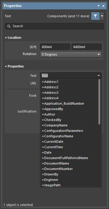
回路図シート上では、特別な文字列はプレフィックス '='(例:=CurrentTime、=CurrentDateなど)によって特徴づけられます。利用可能な特別な文字列のリスト(事前定義されたものもユーザー定義のドキュメントレベルおよびプロジェクトレベルのパラメーターも含む)は、テキスト文字列が選択された状態で、Textフィールドに関連付けられたドロップダウン矢印をクリックすることで表示されます。これはTextモードのPropertiesパネル内で行います。
バリアントレベルで定義されたパラメーターはリストに表示されません。そのようなパラメーターは特別な文字列表記(すなわち=<VariantParameterName>)を使用して参照できます。パラメーターの値は、それが定義されている関連バリアントが現在のバリアントとして設定されたときのみ表示されます。
配置されたテキスト文字列オブジェクトの特別な文字列にアクセスする。
特別な文字列を使用しているテキスト文字列オブジェクトを識別するのに役立つために、特別な文字列の名前を回路図シート上に表示することができます。
Preferencesダイアログの
Schematic – Graphical Editingページで
Display Name of Special Stringオプションが有効になっている場合、各特別な文字列の名前が薄い上付き文字として表示されます(これらの上付き文字は印刷されません)。

特殊な文字列の連結
複数の特殊な文字列と通常のテキスト(固定文字列)は、以下のルールに従って単一のテキスト文字列に連結することができます:
| 要素 |
機能 |
例 |
戻り値 |
| = (イコール) |
後に続く文字列が解釈されなければならない式であることを示します。 |
=Project |
Kame_FMU 例のプロジェクト名がKame_FMU.PrjPcbの場合 |
| + (プラス) |
特別な文字列と固定文字列要素を文字列内で連結するために使用されます。 |
=Project + VariantName |
Kame_FMUDefault 例のプロジェクトのデフォルトバリアントの場合 |
| ' ' (シングルクォート) |
必要な文字列内のどこにでも固定文字列を含めるために使用されます。 |
='Project: ' + Project + ', Variant: ' + VariantName |
Project: Kame_FMU, Variant: Default 例のプロジェクトのデフォルトバリアントの場合 |

特別な文字列はテキストや他の特別な文字列と連結することができます。
特別な文字列の切り捨て
特別な文字列は、Copy()関数とLength()関数を使用して切り捨てることもできます。以下の例は、回路図ドキュメントからファイル拡張子を削除する方法を示しています:
| 特別な文字列 |
動作 |
ドキュメントに配置した場合の結果
Bluetooth_Sentinel.SchDoc |
=DocumentName |
ドキュメントのファイル名をファイル拡張子を含めて返します。 |
Bluetooth_Sentinel.SchDoc |
=Copy(DocumentName,1,length(DocumentName)-7) |
DocumentNameの文字列を、最初の文字からDocumentNameの文字数-7(最後の7文字を切り捨てる)の長さで返します |
Bluetooth_Sentinel |
指定子とネット名からのアクティブリンク
コンポーネントの指定子とネット名は、テキストフレームやノートに含めることができ、アクティブリンクとして機能し、回路図内や生成されたPDF内でのクロスプロービング機能を提供します。
リンクは、テキストフレームまたはノートのPropertiesダイアログのProperties r領域でアクティブとして定義され、@文字に続いてDesignatorまたはNet名を入力することで設定されます。入力すると選択リストが表示されるので、目的のオブジェクトを選択してください。

@文字を入力すると、指定子とネット名のリストが表示されます。リストを検索するには入力を続けてください。
アクティブリンクはテキストフレームまたはノート内のボックスで強調表示され、そのコンポーネントまたはネットにクロスプローブするためにクリックします。指定子の値またはネット名の変更は、既存のアクティブリンクに自動的に適用されます。
 各ライブリンクはボックスで強調表示され、リンクをクリックするとそのコンポーネントまたはネットにクロスプローブします。
回路図エディタでリンクをクリックしたときに使用されるズームおよびディミングレベルは、PreferencesダイアログのSystem - Navigationページで設定されます。
PDFで使用されるズームレベルは、Schematic PDF Settingsダイアログ(OutputJobからのPDF)、またはSmart PDFウィザードで定義されます。
ハイパーリンクテキスト文字列
テキスト文字列は、選択されたテキスト文字列オブジェクトのPropertiesパネルにターゲットURLを入力することで、ウェブサイトのページやローカルまたは共有ドライブ上のドキュメントへのハイパーリンクに変換することができます。これは、設計で使用されるコンポーネントのデータシートへのアクセスを提供する際に、迅速で便利な代替手段を提供します。このようなテキスト文字列は、回路図ソースドキュメントのタイトルブロック内で、自組織のウェブサイトへの有益なリンクを提供することもできます。
URLが必要に応じて設定されると、設計スペース内から使用することができます。そのためには、テキスト文字列の上にカーソルをホバーします。短い遅延の後、URLが表示されるポップアップが現れます。これをクリックすると、定義された好みに応じて、Altium Designer内または外部ブラウザ内でURLが開きます。
ターゲットURLは、
Open internet links in external Web browserオプションの状態に応じて、Altium Designer内でタブ付きドキュメントとして開くか、外部ブラウザで開きます。このオプションは、
Preferencesダイアログの
System – View pageページにあります。
-
ハイパーリンクを設定するときに、
http://プレフィックス付きの完全な URL を入力する必要はありません。たとえば、www.altium.com のように、Web サイトの短縮形のアドレスを入力することもできます。ただし、外部ブラウザーで URL を開く場合は、http://プレフィックスが必要です。
-
ハード ドライブまたは共有ドライブ上のローカル ドキュメントをターゲットに設定する場合は、
file:///C:\Datasheets\ExampleDatasheet.pdfなどのプレフィックスfile:///を使用します。
-
ファイルサーバー上のドキュメントをターゲットとする URL (例:
\\myserver\share\manual.pdf) を使用することもできますが、Smart PDF WizardまたはOutputJob fileファイルを使用して回路図から生成された PDF では、現在そのようなリンクはサポートされていません。ファイル サーバーをネットワーク ドライブにマップし、絶対パスを使用できます。この場合、チームメイトは、生成された PDF ドキュメントでこれらの URL を使用できるように、同じドライブ文字でネットワーク ドライブをマップする必要もあります。
-
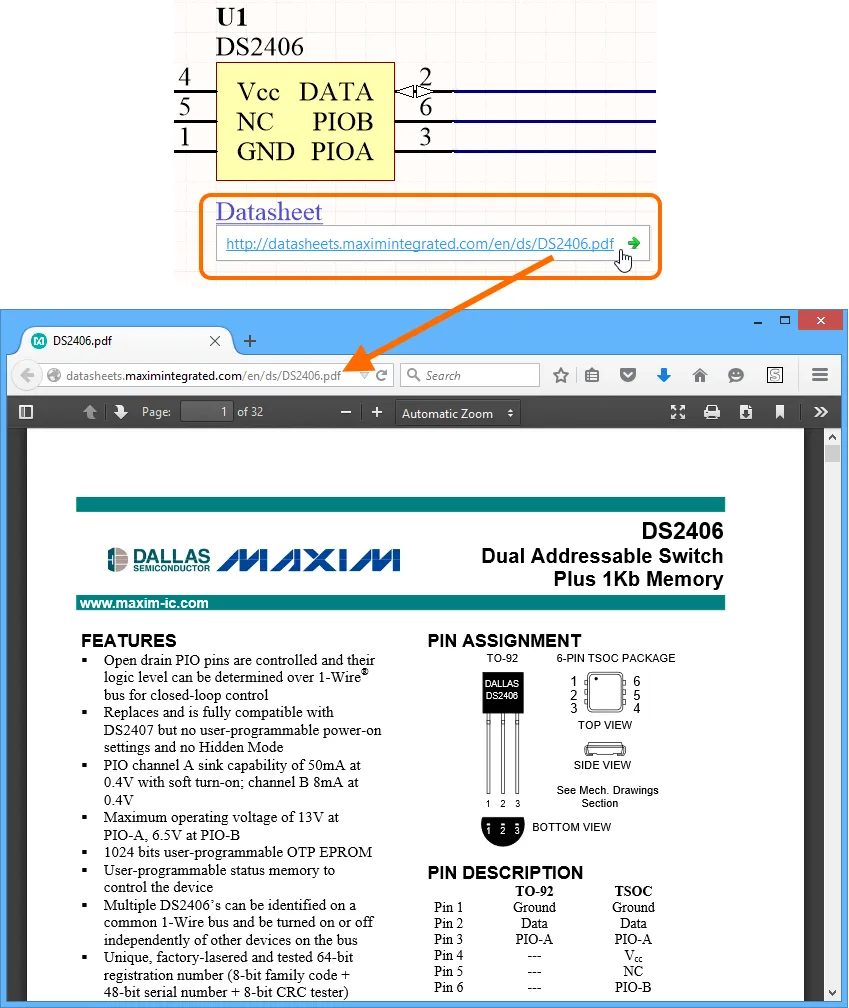
例のハイパーリンクをそのターゲットURLに従っています。
URLを含むポップアップは、ソフトウェアのデザインインサイトシステムの機能です。具体的には、システムのハイパーリンクインサイト機能を有効にすることで得られます。これは、PreferencesダイアログのSystem – Design Insightページで行います。システムの他の要素と同様に、ポップアップの起動スタイルをマウスホバーおよび/またはAlt+ダブルクリックで設定できます。
マウスホバー起動スタイルを使用する場合のポップアップの表示遅延は、マウスホバーディレイスライダーを使用して制御できます。これは、インサイトシステムのすべての側面に対するポップアップに影響しますので、ご注意ください。
また、リンク上で右クリックしてHyperlinkサブメニューからURLにアクセスすることでリンクをたどることができます。これは、ハイパーリンクインサイトが無効になっている場合のリンクのたどり方です。

右クリックメニューからテキスト文字列のURLにアクセスします

