Altium Designer включает возможности импорта проектных данных и экспорта в популярные форматы, такие как STEP и Parasolid, для обмена с MCAD-инструментами.
Поддержка импорта/экспорта STEP-файлов
Altium Designer предлагает расширенные возможности взаимодействия с системами и ПО механического проектирования (MCAD) за счет активного обмена данными физического дизайна. Набор систем и интерфейсов, связывающих домены ECAD и MCAD, также опирается на стандартизированные форматы данных, такие как утвержденный в отрасли протокол STEP (Stандарт для Eбмена Pанными модели изделия), который предоставляет насыщенный информацией формат файла с текстовой кодировкой для данных 3D‑моделей.
Сам формат STEP (*.step или *.stp) определен в спецификации ISO 10303-21 (International Organization for Standardization) для обмена CAD‑данными и поддерживается большинством MCAD‑инструментов и систем. На базовом уровне обмена файлами Altium Designer предлагает как экспорт, так и импорт 3D STEP‑файлов.
Это обеспечивает основу для свободного обмена высококачественными стандартизированными данными 3D‑моделирования между программными средами, что упрощает совместную работу ECAD‑MCAD и повышает качество и точность данных 3D‑моделей. Обратите внимание: Altium Designer поддерживает как STEP AP214, так и устаревший формат AP203 — экспортируемые файлы соответствуют ISO-10303-21 (AP214).
См. страницу ISO 10303-21 specification .
Прочитайте информацию о формате STEP.
Экспорт STEP‑файлов
Важная функция в обмене данными между мирами ECAD и MCAD — возможность перенести печатную плату или многоплатную сборку в ПО механического проектирования для проверки физических зазоров. Это особенно критично, когда конструкция тесно увязана с корпусом изделия, который также выводит периферию платы — органы управления, переключатели, разъемы и дисплеи.
В этом случае присущие формату STEP универсальность и точность позволяют передавать комплексные данные моделирования PCB из Altium Designer в MCAD‑ПО с высокой уверенностью в размерных соотношениях. Затем MCAD‑конструктор может импортировать и разместить 3D STEP‑модель сборки платы в механической модели, чтобы выполнить проверку и/или внести изменения.
Чтобы получить доступ к возможностям экспорта STEP‑файлов в Altium Designer, для вашей установки Altium Designer должны быть включены функции STEP и MBASTEP . Эти функции включены в Altium Designer по умолчанию. Их можно включать/отключать после установки.
Дополнительные сведения об изменении установленной базовой функциональности см. на Installing & Managingстранице (Altium Designer Develop, Altium Designer Agile, Altium Designer).
Использование Exporter
PCB‑документ Altium Designer можно экспортировать в формат STEP. В Outputjob file нажмите [Add New Export Output] и выберите пункт в меню Export STEP . Затем выходные данные экспорта можно сгенерировать напрямую из файла или как часть процесса Project Release.

Либо выберите команду File » Export » STEP 3D в главных меню PCB‑редактора Altium Designer. После запуска команды задайте имя целевого файла и расположение.
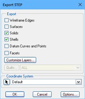
Диалог Export Options, доступный двойным щелчком по добавленному выходу экспорта STEP или запуском команды File » Export » STEP 3D , предоставляет ряд настроек, включая параметры, определяющие, какие объекты платы будут включены в генерируемый файл.
 Экспортированные STEP‑файлы, отображаемые в MCAD‑приложении: на верхнем изображении файл не содержит отверстий в площадках и 3D‑тел, а на нижнем изображении файл включает все объекты.
Options and Controls of the Export Options Dialog
Вариант диалога Export Options открывается при экспорте в файл формата STEP, PARASOLID или VRML. Его содержимое будет немного отличаться в зависимости от формата, а также от того, выполняется ли экспорт с помощью File » Export команды или настроенного генератора выходных данных в составе Output Job файла. Отличия выделены ниже.
Board Options
-
Export Folded Board - установите этот флажок, чтобы экспортировать сложенную rigid-flex плату. Используйте Rate ползунок, чтобы задать величину сгиба — от плоского состояния (сгиб 0%) до полностью сложенного (сгиб 100%).
Обратите внимание: величина сгиба, заданная ползунком
Fold State на панели
PCB при настройке в режиме
Layer Stack Regions mode, станет значением по умолчанию при открытии диалога
Export Options.
-
Skip Free 3D Bodies - включите, чтобы экспортировать без свободных 3D‑моделей.
-
Skip Hidden 3D Bodies - включите, чтобы экспортировать без скрытых 3D‑моделей.
-
Export As Single Part - этот параметр применяется только при экспорте в STEP‑файл. Отметьте, чтобы экспортировать STEP‑файл как одну деталь или как одну модель на компонент. Когда этот параметр включен, STEP‑файл будет сохранен как деталь, а не как сборка.
Components With 3D Bodies
Эти параметры доступны только при открытии диалога через File » Export команду.
Выберите вариант, какие компоненты включать в экспортируемый файл. Параметры позволяют выбрать между полной и ограниченной детализацией, чтобы ускорить экспорт и уменьшить размер файла.
-
Export All - выберите, чтобы экспортировать все компоненты. Этот вариант медленнее и увеличивает размер экспортируемого файла.
-
Export Selected - выберите, чтобы экспортировать только выбранные компоненты. Этот вариант быстрее и уменьшает размер экспортируемого файла.
Вырезы платы всегда включаются в экспорт.
Выбирать конкретные компоненты или отверстия для экспорта проще в 2D. Если вы хотите экспортировать только плату, выберите Export Selected и не выбирайте ничего в документе. Неприкрепленные к PCB, «свободно плавающие» 3D‑тела также будут включены в экспорт. Чтобы не включать их, используйте Export Selected параметр, не выбирая свободно плавающие 3D‑тела.
3D Bodies Export Options
Следующие параметры применяются к компонентам, которым назначены и выдавленные (простые) 3D‑тела, и 3D‑тела STEP‑моделей.
-
Prefer simple bodies - выберите, чтобы экспортировать версию компонента с выдавленным (простым) 3D‑телом.
-
Prefer generic 3D models - выберите, чтобы экспортировать версию с универсальным 3D‑телом.
-
Export both - выберите, чтобы экспортировать обе версии 3D‑тел: выдавленную и универсальную.
Если для компонентов доступны только выдавленные 3D‑тела, они будут экспортироваться всегда.
Copper Export Options
Эти параметры доступны только при экспорте в формат PARASOLID.
Используйте следующие параметры, чтобы выбрать настройки экспорта меди.
-
Export Without Copper - выберите, чтобы экспортировать без меди.
-
Export Copper Only - выберите, чтобы экспортировать только медь.
-
Export Selected Only - выберите, чтобы экспортировать медные объекты, относящиеся к выбранным объектам.
-
Export By Layer - выберите, чтобы экспортировать медь по слоям. В раскрывающемся списке выберите один из следующих слоев:
-
Top Layer
-
Mid-Layer 1
-
Mid-Layer 2
-
Bottom Layer
Выбирайте этот режим, когда нужно экспортировать только медные объекты на выбранном слое, включая кольца сквозных площадок и переходных отверстий на этом слое.
-
Export All - выберите, чтобы экспортировать все.
Если включить параметры Export Copper Only, Export Selected Only или Export By Layer , будут экспортироваться только медные объекты, даже если выбраны параметры экспорта немедных объектов. Если выбрать Export Without Copper или Export All, вы увидите плату и компоненты — в зависимости от других выбранных параметров компонентов.
Pad Holes
Следующие параметры доступны только когда диалог был открыт через File » Export команду.
Используйте следующие параметры, чтобы выбрать, какие отверстия включать в экспортируемый файл. Параметры позволяют выбрать между полной и ограниченной детализацией, чтобы ускорить экспорт и уменьшить размер файла.
-
Export All - выберите, чтобы экспортировать все отверстия на плате. Этот вариант медленнее и увеличивает размер экспортируемого файла.
-
Export Selected - выберите, чтобы экспортировать только выбранные отверстия. Этот вариант быстрее и уменьшает размер экспортируемого файла.
Следующие параметры доступны только когда диалог был открыт через OutJob файл.
-
Export Mechanical Component Pad Holes - установите этот флажок, чтобы экспортировать любые отверстия площадок механических компонентов.
-
Export Electrical Component Pad Holes - установите этот флажок, чтобы экспортировать любые отверстия площадок электрических компонентов.
-
Export Free Pad Holes - установите этот флажок, чтобы экспортировать любые свободные отверстия площадок.
Component Suffix
Используйте следующие параметры, чтобы задать суффикс экспортируемых компонентов.
-
None - к компонентам не будет применен суффикс.
-
Board file name - использовать имя файла универсальной 3D‑модели в качестве суффикса компонента.
-
Custom - выберите, чтобы настроить суффикс компонента. Введите пользовательский суффикс в текстовое поле.
Примечания по экспортированным файлам
-
Если параметры Export Selected (3D Bodies и Pad Holes) были включены в диалоге Export Options, но в PCB‑редакторе в данный момент выбраны no объекты, то сгенерированные STEP‑файлы не будут включать ни один из этих типов объектов.
-
Плата экспортируется всегда. Чтобы исключить все компоненты (экспортировать только плату), включите параметр Export Selected, при этом не выбирая ни одного компонента.
- Если требуется экспортировать только выбранные компоненты, обычно проще выделить их в режиме 2D-отображения.
-
Если выбран параметр Export as Single Part, сгенерированная STEP-модель будет сохранена как одна деталь, а не как сборка из моделей компонентов. Это упрощает экспортируемую STEP-модель, но не позволяет выбирать отдельные компоненты в принимающем MCAD-приложении.
-
STEP-файлы, создаваемые функцией Export 3D, позиционируют графику модели относительно точки начала координат в исходном проекте PCB. ПО, используемое для импорта этого файла, может как учитывать, так и игнорировать содержащуюся в нём инструкцию по расположению — если импортированная модель не отображается, возможно, при текущем масштабе она находится за пределами экрана.
-
Free 3D Bodies — это дополнительные 3D-модели, размещённые в PCB-редакторе, например корпус.
-
3D Bodies Export Options относятся к 3D-телам/моделям, добавленным в посадочные места компонентов в редакторе библиотек PCB. Термин simple bodies относится к объектам 3D Body, полученным выдавливанием, а также цилиндрическим или сферическим.
-
В STEP-файле каждый компонент идентифицируется по своему позиционному обозначению (designator). Если MCAD-конструктору нужно импортировать несколько плат в один MCAD-файл, вероятны конфликты обозначений; чтобы избежать этого, добавьте Component Suffix.
-
Параметр Export Folded Board работает только при наличии в проекте линий сгиба. Чтобы экспортировать плату в частично согнутом виде, перед выполнением команды Export настройте величину сгиба с помощью ползунка Fold State в режиме Layer Stack Region панели PCB. Заданное значение будет автоматически применено в диалоге Export Options.

Частично согнутая rigid-flex плата, экспортированная из PCB-редактора и импортированная в Rhinoceros 3D MCAD design software.
-
Если у вас нет доступа к ПО для механического черчения/просмотра, экспортированный STEP-файл можно проверить, импортировав его обратно в размещённый объект 3D Body object в Altium Designer.
Документ Altium Designer Multi-board Assembly можно экспортировать в формат STEP. Используйте пункт MBA Export STEP в меню [Add New Export Output] в файле Outputjob или выберите команду File » Export » STEP 3D в главных меню редактора Multi-board Assembly в Altium Designer.
Сохранение из IPC Component Wizard
Автоматизированный IPC Compliant Footprint Wizard, который создаёт IPC-совместимое посадочное место в редакторе PCB Library, предоставляет дополнительную возможность сохранить (и предварительно просмотреть) сгенерированную модель посадочного места как 3D STEP-файл. Модель на основе STEP может быть встроена в созданное IPC-совместимое посадочное место, а также сохранена как файл *.step в указанном месте; второй вариант позволяет при необходимости повторно использовать или распространять 3D-модель.
IPC Component Wizard запускается из редактора посадочных мест PCB (Tools » IPC Compliant Footprint Wizard), а опция экспорта STEP включается на предпоследней странице мастера Footprint Destination. Сгенерированная модель STEP-файла будет точно соответствовать размерам компонента, введённым в мастере.
 Помимо возможности сгенерировать и встроить STEP-модель для компонента, мастер также позволяет сохранить её как файл 3D-модели STEP.
Импорт STEP-файлов
Импорт в PCB или в посадочное место PCB Footprint
STEP-файлы можно импортировать и использовать в Altium Designer двумя различными способами, при этом в обоих используется один и тот же механизм. Выбор подхода в основном зависит от того, как STEP-файл будет применяться в проекте:
-
STEP-файл, представляющий механические элементы конечного изделия, например корпус, созданный в MCAD-приложении, обычно импортируется в разводку PCB.
-
STEP-файл, представляющий 3D-тело компонента (скачанное из интернета или созданное локально), обычно импортируется в посадочное место PCB.
И в области PCB, и в области PCB footprint в Altium Designer STEP-файлы импортируются в специализированный объект 3D Body object, который затем размещается и выравнивается по необходимости. Подробнее см. раздел 3D Body Object Placement .
Exporting the Enclosure and Board Shape from MCAD for Use in Altium Designer
Распространённый подход — механический конструктор разрабатывает первоначальную концептуальную модель, чтобы все участники могли представить, как будет выглядеть изделие. Затем механический конструктор уточняет конструкцию корпуса и задаёт начальную форму платы.
Этот корпус и форму платы можно передать ECAD-разработчику, сохранив их из MCAD-инструмента в формате STEP и разместив в рабочем пространстве PCB-редактора. В Altium Designer есть команда, которая позволяет переопределить форму платы ECAD непосредственно по форме платы из MCAD.
STEP — сложный и очень детализированный формат файла. Чтобы повысить успешность передачи данных проекта, учитывайте следующее:
-
Форму платы можно экспортировать внутри корпуса, при условии что она является отдельной подсборкой. Если это сделано, вы сможете переопределить форму платы ECAD по механическому определению несколькими щелчками в PCB-редакторе.
-
По возможности используйте формат AP214.
-
Если доступно, используйте вариант экспорта с поверхностной или твердотельной геометрией.
 и PTC Creo (ранее Pro/E) (второе изображение).")
Подходящие параметры экспорта для SolidWorks (первое изображение) и PTC Creo (ранее Pro/E) (второе изображение).
Импорт в Multi-board Assembly
STEP-модель можно добавить в активный документ Multi-board Assembly с помощью команды Design » Insert STEP Part из главных меню.
Поддержка импорта-экспорта файлов Parasolid
Экспорт файлов Parasolid
Документ PCB в Altium Designer можно экспортировать в формат файла Parasolid. В файле Outputjob file нажмите [Add New Export Output] и выберите пункт в меню Export PARASOLID . Затем выходные данные экспорта можно сгенерировать непосредственно из файла или в рамках процесса Project Release.

Либо выберите команду File » Export » PARASOLID в главных меню PCB-редактора Altium Designer. Параметры экспорта задаются в диалоге Export Options dialog.
Экспорт PCB в формат Parasolid использует Parasolid версии 35.1.
При экспорте panelized PCB (Embedded Board Array) в формат Parasolid в экспортируемом файле траектория фрезеровки (Route Tool Path) прорезается через все слои платы, а также учитываются полости и вырезы платы из исходной платы на панелизированной PCB.
Импорт файлов Parasolid
И в области PCB, и в области PCB footprint в Altium Designer файлы Parasolid импортируются в специализированный объект 3D Body object, который затем размещается и выравнивается по необходимости. Подробнее см. раздел 3D Body Object Placement .
Поддержка импорта файлов деталей SolidWorks
И в области PCB, и в области PCB footprint в Altium Designer файлы деталей SolidWorks (*.sldprt) импортируются в специализированный объект 3D Body object, который затем размещается и выравнивается по необходимости. Подробнее см. раздел 3D Body Object Placement .
3D-модель в формате SOLIDWORKS Parts File (*.SldPrt), созданная в SOLIDWORKS версий 2022, 2023, 2024 или 2025, может быть импортирована при использовании универсальной 3D-модели с объектом 3D Body.
Поддержка экспорта VRML-файлов
Документ PCB в Altium Designer можно экспортировать в формат файла VRML. В файле Outputjob file нажмите [Add New Export Output] и выберите пункт в меню Export VRML . Затем выходные данные экспорта можно сгенерировать непосредственно из файла или в рамках процесса Project Release.

Либо выберите команду File » Export » VRML в главных меню PCB-редактора Altium Designer.
Поддержка импорта-экспорта IDF-файлов
-
Altium Designer поддерживает данные формата IDF до версии 3.0.
-
Чтобы получить доступ к возможностям импорта/экспорта IDF-файлов в Altium Designer, для вашей установки Altium Designer должна быть включена функция IDF . По умолчанию эта функция в Altium Designer включена. Её можно включать/отключать после установки.
Подробнее об изменении установленной базовой функциональности см. на странице Installing & Managing (Altium Designer Develop, Altium Designer Agile, Altium Designer).
Экспорт IDF-файлов
Документ PCB в Altium Designer можно экспортировать в формат файла IDF. В файле Outputjob file нажмите [Add New Export Output] и выберите пункт в меню Export IDF . Затем выходные данные экспорта можно сгенерировать непосредственно из файла или в рамках процесса Project Release process.

Либо выберите команду File » Export » IDF Board в главных меню PCB-редактора Altium Designer.
Диалог File Export IDF предоставляет элементы управления для настройки свойств экспортируемых IDF-файлов. Доступ к диалогу осуществляется двойным щелчком по добавленному выходу экспорта IDF в файле Outputjob или нажатием Save в диалоге Export File после выбора File » Export » IDF Board.

Диалог File Export IDF
Options and Controls of the File Import IDF Dialog
-
Version — выберите соответствующую версию.
-
Units — выберите соответствующие единицы измерения: Imperial или Metric.
-
Exported Drilled Holes
-
All - выберите, чтобы экспортировать все просверленные отверстия.
-
Selected - выберите, чтобы экспортировать только выбранные просверленные отверстия.
-
Larger Than - выберите, чтобы экспортировать только просверленные отверстия, размер которых больше значения, указанного в текстовом поле.
-
Exported Sections - установите флажки нужных разделов.
-
File Compatibility
-
Replace '.' With '_' In Component Names - установите этот флажок, чтобы заменить символ точки на символ подчёркивания в именах компонентов.
-
Replace Blank Component Fields With - введите текст, которым вы хотите заменить пустые поля компонентов.
-
Override Part Number With - включите, чтобы переопределять номера деталей при генерации файлов. В раскрывающемся списке можно выбрать, чем заменить Part Number, используя один из следующих вариантов. Раскрывающийся список доступен только когда включена Override Part Number With опция .
-
Comment
-
Item HRID
-
Revision HRID
-
Library REF
-
<Enter Schematic Parameter>
Для <Enter Schematic Parameter> введите нужный параметр схемы, на основе которого вы хотите формировать имена компонентов, внутри квадратных скобок.
-
Component Outlines From Multiple Component Bodies
-
Use Bounding Component Body - выберите, чтобы использовать ограничивающее тело компонента (bounding component body).
-
Create Sub Components - выберите, чтобы создавать подкомпоненты.
-
Generated Files - экспорт IDF-файлов создаёт два файла: один содержит информацию о физических размерах и форме печатной платы и позициях компонентов, другой — информацию о каждом компоненте, включая имя, размер и форму. Обычно их называют соответственно файлом платы (board) и файлом библиотеки (library). Разные CAD-пакеты используют разные расширения файлов для board и library. Используйте раскрывающийся список, чтобы выбрать расширения board- и library-файлов для генерируемых файлов. Доступные варианты:
-
.brd и .pro
-
.brd и .lib
-
.emn и .emp
-
.bdf и .ldf
-
.idb и .idl
-
.idf и .lib
-
Use Unicode - установите этот флажок, чтобы использовать стандарт Unicode для текста в генерируемых файлах.
Импорт IDF-файлов
Чтобы импортировать IDF-файл в активный документ PCB, выберите команду File » Import » IDF Board в главном меню PCB-редактора Altium Designer. После выбора команды откроется диалог File Import IDF, позволяющий настроить свойства импортируемых IDF-файлов.

Диалог File Import IDF
Options and Controls of the File Import IDF Dialog
-
Offsets - введите требуемые значения смещения для X и Y в текстовых полях.
-
Board File Import Options - установите флажки элементов, которые вы хотите импортировать.
-
OK - нажмите, чтобы запустить процесс импорта.
Поддержка импорта-экспорта IDX-файлов
Поскольку всё больше электронных изделий включает как электрические, так и механические компоненты, а циклы выпуска продуктов сокращаются, возникает реальная потребность в более тесном взаимодействии между областями ECAD и MCAD. Но такое взаимодействие не всегда проходит гладко. Электротехник и механик часто пересылают письма туда-сюда или вынуждены разбираться в инструментах проектирования друг друга — что выбивает их из привычной рабочей среды. Одно из решений — использовать метод совместной работы, который позволяет двум сторонам графически обмениваться идеями и предложениями по изменениям, не покидая привычных рабочих окружений. Такой метод реализован через основанный на XML формат обменного файла — IDX (Incremental Design EXchange format).
С помощью этого промежуточного обменного файла (*.idx) электрический конструктор может экспортировать только те изменения в проекте платы, которые нужны (и полезны) механику. В свою очередь, механик может отправлять предложения по изменениям обратно электрическому конструктору, который затем может импортировать эти изменения в свой проект.
Поддержка этого стандарта совместной работы между ECAD и MCAD доступна в Altium Designer благодаря расширению MCAD IDX Exchange . Это расширение позволяет выполнять инкрементальный обмен данными между Altium Designer и механическими CAD-приложениями (например, SOLIDWORKS), используя формат обмена IDX. Функциональность включает поддержку запросов на изменения, а также передачу геометрии Cu.
-
Altium Designer поддерживает только версию формата IDX 2.0.
-
Чтобы получить доступ к возможностям обмена IDX-файлами в Altium Designer, необходимо установить программное расширение MCAD IDX Exchange . Это расширение можно установить или удалить вручную.
Дополнительные сведения об управлении расширениями см. на странице Extending Your Installation (Altium Designer Develop, Altium Designer Agile, Altium Designer).
-
Обратите внимание: чтобы использовать возможности обмена IDX-файлами в Altium Designer, у вас должна быть активная подписка Altium.
Инициация базового файла для совместной работы
Совместную работу можно начать с любой стороны — либо электрический конструктор создаёт исходный IDX-файл, либо это делает механик. Если это делает электрический конструктор, созданный файл называется базовым файлом ECAD (ECAD Baseline.idx) и затем становится доступным механику. Если это делает механик, файл называется базовым файлом MCAD (MCAD Baseline.idx) и затем становится доступным электрическому конструктору.
Экспорт из Altium Designer (создание базового файла на стороне ECAD)
В Altium Designer основным интерфейсом для совместной работы является панель MCAD IDX Exchange, доступ к которой выполняется нажатием кнопки  в правом нижнем углу Altium Designer при активном PCB-редакторе, после чего в меню выбирается пункт MCAD IDX Exchange.
К панели также можно получить доступ с помощью команды MCAD IDX Exchange из главного Tools меню.
Чтобы начать совместную работу, нажмите кнопку Export Baseline. Появится диалог Export EDMD Baseline, предлагающий параметры, включая экспорт медных объектов.
Экспорт меди делает IDX-файлы значительно больше и замедляет их обработку на стороне MCAD. Кроме того, технология IDX не поддерживает обнаружение изменений для медных объектов.
 Инициируйте совместную работу в Altium Designer, создав базовый файл ECAD.
Импорт в Altium Designer (создание базового файла на стороне MCAD)
Если базовый файл был создан на стороне MCAD, его можно импортировать в Altium Designer с помощью команды File » Import » MCAD IDX Baseline. Откроется диалог Import MCAD Baseline. Используйте его, чтобы найти и указать базовый файл MCAD (MCAD Baseline.idx), а также PCB-документ, с которым должны быть синхронизированы предлагаемые изменения.
 Примите совместную работу в Altium Designer, импортировав базовый файл MCAD.
-
Input MCAD Baseline File - нажмите
 , чтобы найти и выбрать нужный IDX-файл для импорта.
-
Output PCB File - нажмите , чтобы найти и выбрать нужный PCB-файл, с которым должны быть синхронизированы предлагаемые изменения.
После импорта базового IDX-файла MCAD совместная работа продолжается через панель MCAD IDX Exchange .
Папка совместной работы
При инициации совместной работы из Altium Designer (создание базового IDX-файла) в исходном проекте платы будет создана папка совместной работы. Имя папки формируется на основе имени PCB-документа в виде <PCBDocumentName>.PcbDoc_EDMD. Папка будет содержать два файла:
-
AD_EDMD_State.xml
-
ECAD Baseline.idx
Быстро открыть созданную папку можно из панели MCAD IDX Exchange, нажав элемент управления Show In Explorer (доступен только после первичного экспорта) или нажав кнопку  , затем выбрав пункт Open Collaboration Folder в связанном меню.

Создание папки и базового файла.
Синхронизация изменений
Панель MCAD IDX Exchange предоставляет элементы управления для поддержания синхронизации изменений между областями ECAD и MCAD. Изменения предлагаются через файлы IDX Changes:
-
Если механик предложил изменения и отправил их в новом файле IDX Changes, панель позволяет принять (импортировать) эти изменения в проект PCB для рассмотрения.
-
Если в плату были внесены изменения, панель может обнаружить эти изменения (кроме изменений меди) и вывести их списком, готовым к экспорту в файл IDX Changes, который затем становится доступным механику.
Обнаружение и экспорт изменений платы
Если вы внесли изменение в PCB-документ, например удалили компонент, это изменение можно обнаружить, нажав кнопку  в верхней части панели MCAD IDX Exchange. Обнаруживаемые изменения будут перечислены в области Board Changes панели в виде:
-
Object - например, позиционное обозначение компонента.
-
Change - например, Removed для компонента, удалённого из проекта, или Added для добавленного.
-
Status - здесь будет Proposed, поскольку изменение исходит со стороны ECAD.
-
Proposition Comment - примечание, поясняющее изменение механику. Введите при необходимости.
 Обнаружение изменений платы.
После того как все изменения внесены, обнаружены и добавлены комментарии к предложениям, эти изменения можно экспортировать с помощью кнопки  . Будет создан файл IDX Changes (ECAD Changes n.idx).

После внесения предлагаемых изменений в плату выполните экспорт, чтобы создать файл IDX Changes и отправить эти предложения механику.
Теперь механику нужно импортировать и просмотреть предложения по изменениям на своей стороне. Затем он примет или отклонит каждое предложенное изменение и отправит ответ в файле IDX Response (MCAD Response n.idx). После получения импортируйте ответ с помощью кнопки  . Чтобы применить изменения из файла ответа, нажмите кнопку
  , при этом будет сформирован файл IDX Response со стороны ECAD обратно механику (ECAD Response n.idx).
Этот «handshaking» гарантирует, что обе стороны синхронизированы с внесёнными изменениями.
Чтобы отказаться от предложенных изменений, нажмите кнопку

; список
Board Changes будет очищен.
Импорт изменений
Если механический конструктор предлагает изменения, они будут представлены в файле IDX Changes (MCAD Changes n.idx). Импортируйте изменения с помощью кнопки  на панели. Изменения будут перечислены в области Changes from Mechanical CAD панели в виде:
-
Object - например, позиционное обозначение компонента.
-
Change - например, Moved для компонента, который был перемещён в пределах проекта.
-
Status - это будет Proposed, поскольку изменение исходит со стороны MCAD.
-
Proposition Comment - примечание, поясняющее изменение для разработчика электрической части.
 Изменения, предложенные механическим конструктором, импортированные на панель.
Теперь вам, как разработчику электрической части, нужно просмотреть и по очереди принять или отклонить каждое предложенное изменение. Чтобы принять предложенное изменение, установите соответствующий флажок Accept . Чтобы отклонить — оставьте его снятым. Также вы можете ввести ответ в соответствующее поле Response Comment.
После того как все предложенные изменения будут приняты/отклонены, нажмите кнопку . Принятые изменения будут применены к документу PCB и будет создан файл IDX Response (ECAD Response n.idx), готовый к отправке обратно механическому конструктору.
Сброс совместной работы
Чтобы полностью сбросить совместную работу по проекту, нажмите кнопку , затем выберите пункт Reset Collaboration в связанном меню. Все текущие записи на панели будут очищены и все файлы в папке совместной работы будут удалены. Это вернёт вас к исходной точке: можно экспортировать базовый файл или импортировать его и начать совместную работу заново.
Обратите внимание: любые изменения, применённые к проекту до сброса, сохранятся.

 Локализовано с помощью ИИ