実際にボードに取り付けられるコンポーネントは、設計キャプチャ中には回路図シンボルとして、ボード設計のためにはPCBフットプリントとして表されます。Altium Designerコンポーネントは以下の方法で使用できます:
- ローカルライブラリから作成され、配置されるか、または
- デザインチーム全体がアクセス可能な接続されたワークスペースから直接配置されます。
この文書では、回路図ライブラリ(
*.SchLib)の作成と管理について説明します。コンポーネントシンボル自体の作成について詳しくは、
回路図シンボルの作成ページを参照してください。
シンボルは、回路図エディタから回路図ライブラリにコピーされたり、回路図ライブラリ間でコピーされたり、回路図シンボル生成ツールや描画ツールを使用して最初から作成されます。
新しい回路図ライブラリの作成
新しい回路図ライブラリを作成するには、メインメニューからファイル » 新規作成 » ライブラリコマンドを選択し、新規ライブラリダイアログのファイル領域から回路図ライブラリオプションを選択します。
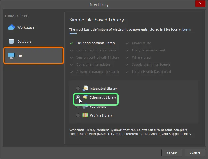
作成をクリックすると、Schlib1.SchLibという名前の新しい回路図ライブラリドキュメントが作成され、プロジェクトパネルに表示され、空のコンポーネントシートComponent_1が表示されます。
ライブラリの内容は、SCHライブラリパネルに表示されます。
これで、新しい回路図ライブラリで回路図シンボルエディタのコマンドを使用して、回路図コンポーネントの追加、削除、または編集を行う準備が整いました。
回路図ドキュメントから回路図ライブラリを作成する
アクティブプロジェクトの回路図ソースドキュメントに使用されているすべてのコンポーネントの回路図ライブラリを作成することもできます。設計 » 回路図ライブラリを作成をクリックすることで行えます。これは、完成した設計の正確な作業ライブラリやアーカイブを作成したい場合に非常に便利です。同じライブラリ参照を持つが内部構造が異なるコンポーネントがある場合、 ![]() コンポーネントグループ化ダイアログが開き、グループ化の目的で使用するパラメータを指定できます。
コンポーネントグループ化ダイアログが開き、グループ化の目的で使用するパラメータを指定できます。
アクティブプロジェクトの全ての回路図ソースドキュメントが開かれ、まだの場合は自動的に開かれ、ライブラリドキュメント(<ProjectName>.SchLib)が自動的に作成されプロジェクトに追加されます。このドキュメントは回路図シンボルエディタでアクティブドキュメントとして開かれます。ライブラリには、設計で使用される全てのコンポーネントが含まれます。作成されたファイルは、プロジェクトパネルのLibraries\Schematic Library Documentsサブフォルダの下のプロジェクトの一部として表示されます。ファイルは初期状態ではハードディスクに保存されていません。
回路図シートからの回路図ライブラリの作成
アクティブな回路図シートから新しい回路図コンポーネントシンボルを作成でき、そのシート上のポートがコンポーネントのピンになります。これを行うには、メインメニューから設計 » シートからコンポーネントを作成コマンドを選択するか、設計オブジェクトから離れたメイン設計スペース内を右クリックして、コンテキストメニューからシートアクション » シートからコンポーネントを作成コマンドを選択します。
コマンドを起動すると、シンボルオプションダイアログが表示されます。このダイアログを使用して、ソースシート上のポートに関連して、シンボルの高さと幅、ピンの長さ、およびピンのスタイルを定義します。
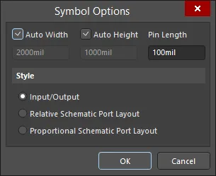
「シンボル オプション」ダイアログ
ダイアログでOKをクリックすると、新しいコンポーネントが作成され、回路図ドキュメントの名前で命名され、新しい回路図ライブラリドキュメント(Schlib1.SchLib)に作成されます。ライブラリはアクティブドキュメントとして開かれ、新しいコンポーネントがそのライブラリ内のアクティブコンポーネントとして提示されます。
ソースの回路図シートにポートが含まれていない場合でも、新しいコンポーネントは作成されますが、シンボルグラフィックスはありません。
新しい回路図コンポーネントの作成
回路図ライブラリには任意の数のコンポーネントシンボルを作成できます。既存のライブラリに新しい回路図コンポーネントを作成するには、メインメニューまたはデザインスペースの右クリックメニューからツール » 新規コンポーネントを選択するか、SCHライブラリパネルのDesign Item ID領域の下にある追加ボタンをクリックします。
コマンドを起動すると、新規コンポーネントダイアログが開きます。ダイアログのDesign Item IDフィールドを使用して、コンポーネントに適切な名前を付けてください。
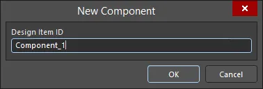
「新しいコンポーネント」ダイアログ
OKをクリックすると、この名前の新しいコンポーネントがライブラリに作成され、空のコンポーネントシートがデザインスペースで開かれ、アクティブになります。
新しいライブラリには常に1つの空のコンポーネントが含まれているため、Component_1をリネームしてコンポーネントの作成を始めることもできます。これを行うには、SCH LibraryパネルのDesign Item IDリストからComponent_1を選択し、パネルの編集ボタンをクリックするか、Component_1をダブルクリックしてコンポーネントモードのプロパティパネルを開きます。その後、Design Item IDフィールドにそのコンポーネントを一意に識別する新しいコンポーネント名を入力し、Enterを押します。
アクティブライブラリから現在のコンポーネントを削除するには、メインメニューからツール»コンポーネントの削除を選択するか、デザインスペース内を右クリックしてコンテキストメニューからツール»コンポーネントの削除を選択します。コンポーネントは、SCHライブラリパネルから直接削除することもできます。設計項目IDリストで必要なコンポーネントを選択し、リストの下にある削除ボタンをクリックするか、右クリックしてコンテキストメニューから削除コマンドを選択します。パネルを使用してコンポーネントを削除する場合、複数の削除を行うことができます。
回路図コンポーネントへのモデルの追加
回路図コンポーネントには、任意の数のPCBフットプリントモデルを追加できるだけでなく、回路シミュレーションや信号整合性分析に使用されるモデルファイルも追加できます。コンポーネントに複数のモデル(例えば、複数のフットプリント)がある場合、回路図上にコンポーネントを配置する際に、プロパティパネルで適切なモデルを選択できます。モデルの入手方法としては、自分で作成するか、インターネットからベンダーのモデルファイルをダウンロードすることができます。PCBライブラリには、任意の数のPCBフットプリントを含めることができます。
3Dモデルは、コンポーネントシンボルに直接リンクされていません。代わりに、3DモデルはPCBフットプリント内に配置されます。なぜかというと、3Dモデルはフットプリントに対して正しく回転させ、整列させ、位置を決める必要があるため、これをフットプリントエディタで行うことが理にかなっています。3Dモデルの扱い方やフットプリントへの配置方法について詳しくは、
PCBフットプリントの作成を参照してください。
次の方法で現在のコンポーネントにモデルを追加できます:
-
デザインスペースの下部にあるモデル領域から(デザインスペースの右下にある逆さ矢印/キャレット記号をクリックしてください。以下の画像に示されています)。

デザインスペースのモデル領域にアクセスするために強調表示されたキャレット記号をクリックしてください。
-
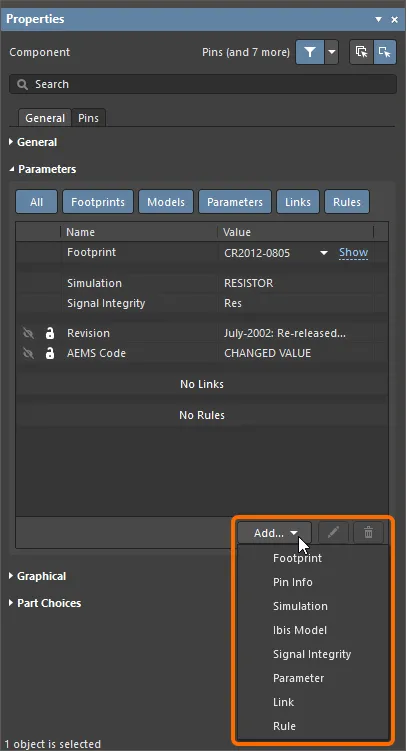
コンポーネントモードのプロパティパネルのパラメータ領域にある追加ドロップダウンを使用して、モデルを選択します。
-
回路図シンボルエディターのモデルマネージャーダイアログ(ツール » モデルマネージャー、またはSCHライブラリパネル内のコンポーネントを右クリックしてコンテキストメニューからモデルマネージャーを選択)を使用すると、アクティブな回路図ライブラリ内のすべてのコンポーネントのコンポーネントモデルを表示および整理できます。例えば、同じモデルを複数の選択されたコンポーネントに追加することができます。

モデルマネージャーダイアログ
モデルマネージャーダイアログのオプションとコントロール
- マスク – このフィールドにコンポーネント名を入力して内容をフィルタリングします。ワイルドカード文字として"
*"を使用します。
- コンポーネントリスト – 現在の回路図ライブラリに存在するすべてのコンポーネントとその説明をリストします。
- モデルリスト – 選択されたコンポーネントに関連するすべてのモデルをリストします。この領域の右クリックメニューには、モデルを追加、コピー、貼り付け、削除、または編集するコマンドが含まれています。
- 追加 – モデルオプションのリストから選択するためのドロップダウンにアクセスするためにクリックします。各オプションには、必要に応じてカスタマイズして希望のモデルを追加するための関連するダイアログが開きます。
- コピー – リストから希望のモデルをコピーするためにクリックします。
- 貼り付け – リストにモデルを貼り付けるためにクリックします。新しいモデルはリストの最後に表示されます。
- 削除 – 選択されたフットプリントを削除するためにクリックします。
- 編集 – モデルの割り当てを編集できる対応するダイアログを開くためにクリックします。
- プレビューを更新 – モデルプレビューを更新するためにクリックします。2Dと3Dプレビューを切り替えるには2D/3Dをクリックします。
モデルをシンボルにマッピングする
モデルをリンクするプロセスの一環として、コンポーネントに関する情報を回路図から対象モデルにマッピングする必要があります。
ドメイン固有の情報は、IBIS、MDL、CKTファイルなど、事前に定義された形式のモデルファイルに存在します。システムがそのドメイン固有の情報にアクセスするために必要な他の情報には、回路図のシンボルとドメイン固有のモデル間のピンマッピングやネットリストが含まれます。この情報は、モデルが追加または編集されるときに開く、ドメイン固有のモデルエディターで定義されます。モデルファイルを参照するだけでなく、そのモデルの種類に必要なピンマッピングやネットリスト情報も含まれます。
これらはSPICEに組み込まれている事前定義されたアナログデバイスモデルの数です。これらのコンポーネントタイプには、別のモデルファイルは必要ありません。モデル化に必要なすべての情報は、SIMモデルエディタで設定されます。
モデルファイルの検索場所
回路図シンボルエディタでコンポーネントにモデルを追加すると、モデルはリンクされます。モデルデータはコピーされたり、回路図コンポーネントに保存されたりしません。これは、リンクされたモデルがライブラリ作成時およびコンポーネントが回路図シートに配置されるときに利用可能である必要があることを意味します。ライブラリエディタで作業しているとき、コンポーネントからモデル情報へのリンクは、以下の有効な検索場所を使用して解決されます:
- 現在のライブラリパッケージプロジェクトに含まれているライブラリが最初に検索されます。
- 現在インストールされているライブラリリストにあるPCBライブラリ(統合ライブラリではない)が次に検索されます。注:ライブラリのリストは順序付けることができます。
- 最後に、プロジェクトの検索パスに位置する任意のモデルライブラリが検索されます。検索パスはプロジェクトオプションダイアログの検索パスタブ(プロジェクト » プロジェクトオプション)で定義されます。注:検索パス上のライブラリはモデルを探すためにブラウズすることはできませんが、コンパイラはモデルを検索する際にそれらを含めます。
利用可能なデータベースおよびファイルベースのライブラリの管理セクションを参照して、ファイルベース&データベースライブラリでのコンポーネント検索ページで、回路図シンボルエディタと回路図エディタでモデルがどのように検索されるかについての詳細情報をご覧ください。
回路図コンポーネントにフットプリントを追加する
現在の回路図コンポーネントにフットプリントを追加するには、上記で説明されているようにモデルを追加するオプションを選択する際にフットプリントを選択します。PCBモデルダイアログが開きます。
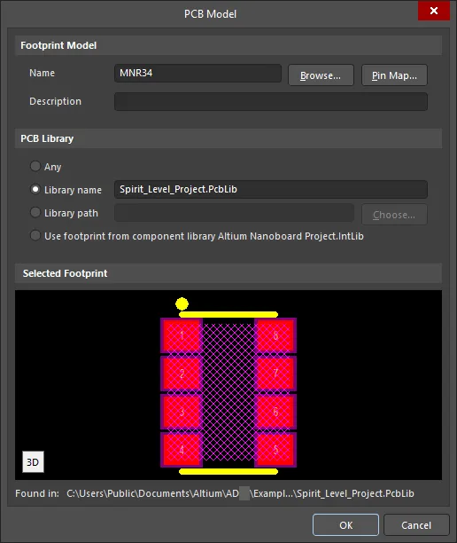
「PCBモデル」ダイアログ
PCBモデルダイアログのオプションとコントロール
フットプリントモデル
- 名前 - フットプリントの名前を表示します。
- 参照 - ライブラリを参照ダイアログを開いて、目的のフットプリントを検索します。
- ピンマップ - モデルマップダイアログを開いて、回路図のシンボルとPCBフットプリント間のピンをマッピングします。
- 説明 - フットプリントに関する意味のある説明を入力します。
PCBライブラリ
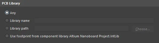
- 任意 - 現在利用可能なすべてのライブラリで目的のフットプリントを検索するために有効にします。
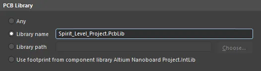
- ライブラリ名 - 名前付きライブラリで目的のフットプリントを検索するために有効にします。テキストフィールドに直接ライブラリ名を入力します。
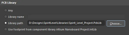
- ライブラリパス - 指定された場所にある名前付きライブラリで目的のフットプリントを検索するために有効にします。選択ボタンをクリックしてパスを選択します。
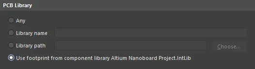
- コンポーネントライブラリからフットプリントを使用する - このオプションは、コンポーネントが統合ライブラリやサーバーなどのコンパイル済みライブラリから配置された場合に有効になります。必要に応じて、配置されたコンポーネントに対して異なるソースPCBライブラリを選択するために上書きできます。
選択されたフットプリント
この領域では、目的のフットプリントのプレビューが表示されます。プレビューの左下にあるアイコンをクリックすると、2Dモードと3Dモードを切り替えることができます。指定されたPCBライブラリでフットプリントが見つからない場合、表示エリアは空白になります。
PCBモデルダイアログの上部には、フットプリントの名前を含める必要がある名前フィールドがあります。名前を直接入力するか、参照ボタンを使用して、 ![]() 参照ライブラリダイアログを使用して利用可能なフットプリントライブラリから探すことができます。ライブラリドロップダウンは、利用可能なライブラリのリストにアクセスするためのものです。
参照ライブラリダイアログを使用して利用可能なフットプリントライブラリから探すことができます。ライブラリドロップダウンは、利用可能なライブラリのリストにアクセスするためのものです。 ボタンをクリックすると、ライブラリを追加または削除できる利用可能なファイルベースのライブラリダイアログが開きます。目的のフットプリントが現在のライブラリのいずれにもない場合は、検索ボタンを使用してファイルベースのライブラリ検索ダイアログを開き、検索する必要があります。
PCBモデルダイアログの下部には、そのモデルがどこで見つかったかを示すテキスト文字列があります。
ソフトウェアがモデルを見つける能力は、どこでモデルを探すかを定義する設定に影響されます。これはモデル名のすぐ下の設定です。オプションはAny(すべての利用可能なライブラリを検索)から、Integrated Library(統合ライブラリ)やServer(サーバー)までの範囲で、これはモデルが指定された統合ライブラリまたはワークスペースからのみ使用できることを示します。
PCBモデルダイアログには以下のオプションが含まれます:
| ライブラリオプション |
動作 |
ダイアログ設定 |
| 任意 |
利用可能な全てのライブラリを検索して、一致するモデルを探します。 |
 |
| ライブラリ名 |
この名前の利用可能なライブラリのみを検索して、一致するモデルを探します。 |
 |
| ライブラリパス |
この名前で、この場所にあるライブラリのみを検索して、一致するモデルを探します。 |
 |
| 統合ライブラリ |
コンポーネントが配置された統合ライブラリ内のモデルのみを検索します。統合ライブラリが利用可能である必要があります。 |
 |
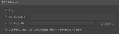
| サーバー |
このコンポーネントが配置されたワークスペースから、モデルを検索します。ソフトウェアはそのワークスペースに接続されている必要があります。 |
 |
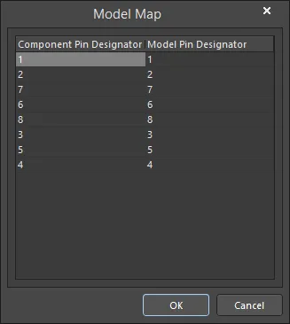
リンクされたフットプリントのピンマッピングを設定するには、PCBモデルダイアログでピンマップをクリックし、モデルマップダイアログを開いてピン-パッドペアに必要な編集を行います。回路図シンボルピンの指定子プロパティを、PCBフットプリントの場合はパッドの指定子に相当するモデルピン指定子にマッピングしていることに注意してください。
- コンポーネントピン指定子列 - すべての回路図シンボルピンをリストします。このフィールドは編集できません。
- モデルピン指定子列 - モデルピン番号をリストします。この例では、割り当てられたPCBフットプリントのパッドが表示されます。これらのフィールドを編集して、PCBパッドをそれに相当する回路図シンボルピンに一致させます。
コンポーネントのピンを複数のモデルピンにマッピングするには、モデルピン指定子列の適切なセルに、コンマで区切られたモデルピン番号のリストを入力します。
回路図コンポーネントにシミュレーションモデルを追加する
新しいコンポーネントを作成する場合、通常はデバイスベンダーのサイトからSPICEモデルを入手します。現在の回路図コンポーネントにシミュレーションモデルを追加するには、モデルを追加するオプションを選択する際にシミュレーションを選択します。上記のように説明されています。Sim Model ダイアログが開きます。このダイアログでモデルの選択と回路図シンボルピンからモデルピンへのマッピングが行われます。
SPICEモデルウィザード(ツール » XSpiceモデルウィザード)も使用できます。これを使用して、コンポーネントに追加する特定のSPICEモデルタイプを作成できます:詳細を学ぶ。
回路図ステージでのモデルの追加
回路図の段階では、設計は論理的に接続されたコンポーネントの集まりです。設計をテストまたは実装するために、例えば、回路シミュレーション、PCBレイアウト、信号整合性分析などが必要になりますが、これを実現するためには、ターゲットドメインに適した各コンポーネントのモデルが必要です。
-
フットプリントは、プロパティパネルのパラメータ領域に追加することで回路図のコンポーネントにリンクされます。追加ドロップダウンをクリックし、フットプリントを選択してPCBモデルダイアログを開き、フットプリントを設定します。

-
モデルは、プロパティパネルのパラメータ領域に追加することで回路図のコンポーネントにリンクされます。追加ドロップダウンをクリックし、シミュレーションまたはIbisモデルを選択して、それぞれのダイアログを開きます。
コンポーネントに詳細を追加するためのパラメータの使用
コンポーネントパラメータは、コンポーネントに関する追加情報を定義する手段です。パラメータを使用すると、コンポーネントに関する追加のテキスト情報を定義できます。これには、電気仕様(例:ワット数や許容誤差)、購入または在庫の詳細、設計者のメモ、コンポーネントのデータシートへの参照など、基本的にはあなたが選んだ任意の目的のためのデータが含まれます:会社がBOMに必要とするデータ、メーカーのデータ、コンポーネントデータシートへの参照、または設計指示情報(例:設計ルールやPCBクラスへの割り当てなど)。
パラメータは、コンポーネント作成時に回路図ライブラリエディタでプロパティパネルを使用して定義できます。
コンポーネントへのパラメータの追加
個々のコンポーネントに対して、パラメータはコンポーネントモードのプロパティパネルのパラメータ領域で追加されます。前述のように、これはライブラリ内またはコンポーネントが回路図シートに配置された後に行うことができます。
以下の手順で、回路図のコンポーネントにパラメータを追加します:
- SCHライブラリパネルでコンポーネント名をダブルクリックして、コンポーネントモードのプロパティパネルを開きます。
- パラメータ領域で、追加ドロップダウンからパラメータを選択します。
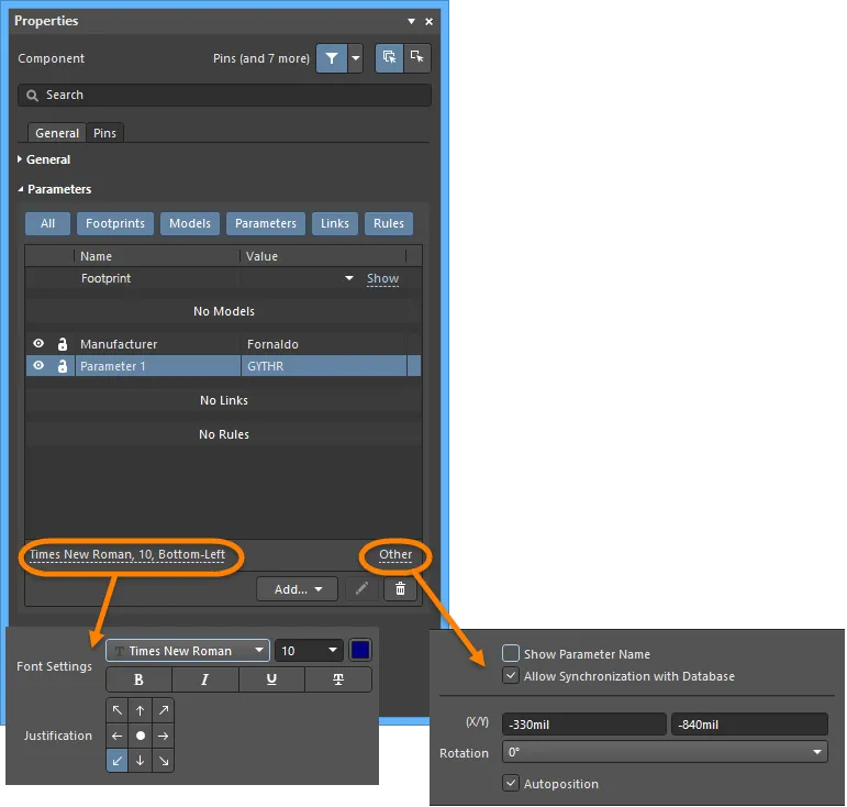
- パラメータの希望する名前と値を入力します。
- パラメータの表示オプションが有効に設定されていることを確認します(
 )コンポーネントが回路図シートに配置されたときに名前と値が表示されるようにする場合。
-
フォントリンクとその他をクリックして、パラメータ領域の下部にある追加のオプションにアクセスし、パラメータを設定します。
パラメータをデザインスペースで選択して、
プロパティパネルを
パラメータモードで開き、パラメータを設定することもできます。
複数のコンポーネントにパラメータを追加する
パラメータは各コンポーネントの重要な要素であり、多くのパラメータが複数のコンポーネントで使用されることが一般的です。各コンポーネントに個別に追加するだけでなく、パラメータマネージャコマンド(ツール » パラメータマネージャ)を使用して、複数のコンポーネントに追加することもできます。パラメータの追加や削除だけでなく、複数のコンポーネントにわたってパラメータの値を編集することもできます。
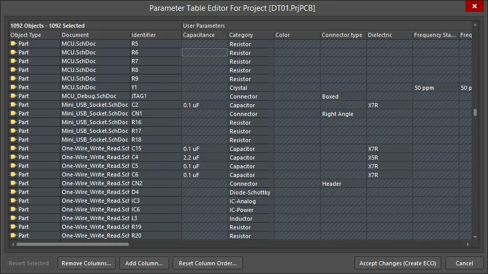
すべてのコンポーネントにわたるすべてのパラメータを編集できるパラメータテーブルエディタダイアログ。
複数のパラメータを編集する際の注意点:
- パラメータは、ライブラリ内のコンポーネントや、回路設計で使用されるコンポーネント全体で編集できます。同じプロセスを使用して、回路図または回路図ライブラリエディタでツール » パラメータマネージャを選択してプロセスを開始します。
- パラメータはさまざまなオブジェクトに追加できるため、最初のステップは、パラメータエディタオプションダイアログで、どのオブジェクトタイプでパラメータを編集するかを選択することです。
- パラメータの編集は、パラメータテーブルエディタダイアログで行われます。ダイアログは異なる方法でアクセスできるため、ダイアログのキャプションは変更される場合があります。アクセス方法に関係なく、ダイアログでの作業方法は同じです:標準のWindows選択キーストロークを使用して関心のあるセルを選択し、右クリックして編集アクションを選択します。
- 変更は即時には行われません。エンジニアリング変更命令(ECO)を介して行われます。
- 変更されている各セルは、小さな色付きアイコンでマークされます。パラメータテーブルエディタダイアログページで、各アイコンの説明を参照してください。
パラメータをコンポーネントのコメントフィールドにマッピングする
回路図に表示されるデフォルトのコンポーネントパラメータは、指定子とコメントです。設計が回路図エディタからPCBエディタに転送されると、指定子とコメントの文字列も、ボード上に簡単に表示できるデフォルトの文字列です。
例えば、容量と呼ばれるパラメータの値を回路図とPCB上に表示するために、文字列の間接参照として知られる技術を使用して、任意のコンポーネントパラメータをコンポーネントのコメントフィールドにマッピングすることができます。
これは、パラメータ名を=ParameterNameの形式で入力することで行います。例えば、コンポーネントパラメータCapacitanceの値をコンポーネントのCommentフィールドにマッピングするには、PropertiesパネルのCommentフィールドに=Capacitanceという文字列を入力します。下記のように表示されます。=ParameterName'の構文を使用して定義された文字列は、特別な文字列と呼ばれます。
特別な文字列は、画面表示用に自動的に変換されます。特別な文字列としてマッピングされたパラメータに値がない場合、PreferencesダイアログのSchematic - Graphical EditingページでDisplay Names of Special Strings that have No Value Definedオプションが有効になっている場合、パラメータ名が灰色で表示されます。このオプションが無効の場合、何も表示されません。
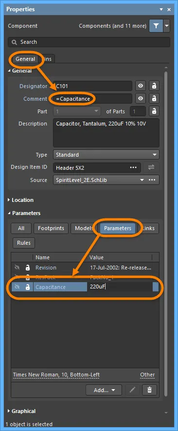
特別な文字列機能を使用して、任意のパラメータ値をコンポーネントのコメントにマッピングします。
特別な文字列を使用すると、任意のパラメータを任意の文字列にマッピングできます。文字列は、コンポーネント文字列、回路図シートに配置された自由な文字列、または回路図テンプレートに配置された文字列のいずれかにすることができます。パラメータは、コンポーネントパラメータ、ドキュメントパラメータ、またはプロジェクトパラメータのいずれかにすることができます。特別な文字列について詳しくはこちらを参照してください。
参照情報へのクリック可能なリンクの定義
パラメータ領域は、プロパティパネルのコンポーネントモードで、追加ドロップダウンをクリックしてからリンクを選択することでリンクを追加できます。この機能は、データシートやメーカーのウェブサイトへのリンクを含めるために使用できます。コンポーネントには任意の数のリンクを定義できます。

リンクは次のように設定する必要があります:
- 名前 - メニューに表示されるエントリを定義するために使用されます。
- Url - ターゲットドキュメントを定義するために使用されます。以下の例は有効なエントリです:
C:\Design_Projects\Schematics\Modifications.txtC:\Design_Projects\Schematics\MyDataSheet.pdfhttps://www.altium.comwww.altium.com/documentation
パネルに表示されるリンクはライブであるため、リンクテキストをクリックすると、URLがお好みのブラウザに読み込まれます。既存のリンクを編集するには、リンクテキストから離れたセル内の任意の場所をクリックし、その後編集ボタンをクリックします。
配置された回路図コンポーネントを右クリックすると、コンテキストメニューからリンクにアクセスできます。名前付きリンクはいくつでも定義できますが、回路図エディタの右クリック参照コンテキストメニューで利用できるのは最初の9つだけです。追加の名前付きリンクは回路図エディタの参照メニューには表示されませんが、生成されたPDFには含まれ、PDFドキュメント内でコンポーネントがクリックされたときにPDFからライブリンクとして機能します(下記参照)。

シート上のコンポーネントを右クリックして、コンポーネントリンクにアクセスします。
コマンドを実行すると、指定されたターゲットドキュメントが開きます。WebベースのURLターゲットページが直接開きます(利用可能な場合)。PDFやテキストドキュメントの場合、以下のようにドキュメントの検索が行われます:
- パスが指定されている場合、まずこの場所が検索されます。
- この場所でドキュメントが見つからない場合、またはパスが指定されていない場合、Altium Designerのインストールフォルダ内の
\Helpフォルダが検索されます。
以前のバージョンのAltium Designerソフトウェアでは、HelpURLと呼ばれる特別なパラメータがサポートされていました。コンポーネントにこのパラメータが含まれている場合、回路図コンポーネント上でカーソルをホバーしている間にF1キーが押されたり、コンポーネントの右クリックメニューから参照» ヘルプコマンドが選択されたりすると、HelpURLパラメータで定義されたリンクまたはドキュメントがWindowsに渡され、参照されたURLまたはファイルが開かれます。この機能はもうサポートされていません。コンポーネントに既存のHelpURLパラメータがある場合、上記のようにコンポーネントリンクに置き換える必要があります。
回路図から生成されたPDFには、Smart PDF機能を使用するか、OutputJobファイルから生成されたPDFを介してリンクを含めることもできます。下の画像は、PDF内でコンポーネントパラメータのリストがどのように表示されるかを示しています。URLであるものは、PDFからその場所へブラウズするためにクリックできます。コンポーネントパラメータとリンクは、コンポーネントパラメータを含めるオプションをSmart PDFウィザードまたはOutputJobオプションの生成設定で有効にすることにより、生成されたPDFにも含めることができます。
PDFは、Smart PDFウィザードを介して、またはOutputJobから直接回路図から生成することができます。PDF内のコンポーネントをクリックすると、下に示すようにパラメータが表示されます。

PDF内のコンポーネントをクリックしてパラメータを表示します。リンクタイプのパラメータをクリックすると、対象が開きます。
HelpURLとComponentLinksは、Device Independent Path形式で定義されている場合、PDF内でリンクになることができます - Acrobatは、リンクがすべてのオペレーティングシステムで機能することを保証するためにこれを要求します。Altium Designer内では、Windowsパス形式とDevice Independent Path形式の両方がHelpURLとComponentLinksで使用できます。Acrobat内からリンクを機能させたい場合は、Device Independent Path形式を使用して定義する必要があります。
- Windowsパス構文:
C:\MyFolder\MyFile.pdf
- デバイス独立パス構文:
/C/MyFolder/MyFile.pdf
リンクの最後に#page=<PageNumber>を含めると、特定のページでターゲットPDFを開くことができます。
コンポーネントの確認とレポートの生成
新しいコンポーネントが正しく作成されたかを確認するために、いくつかのレポートを生成することができます。レポートを生成する前に、ライブラリファイルが保存されていることを確認してください。
ライブラリリスト
ライブラリリストは、アクティブなライブラリドキュメントから、各コンポーネントとその対応する詳細をリストアップします。
- レポート » ライブラリリストを選択します。
-
ASCIIテキストファイル(<LibraryName>.rep)が生成され、アクティブなドキュメントとして開かれます。このファイルには、ライブラリ内のコンポーネントの総数と、利用可能な場合は各コンポーネントの名前と説明がリストされています。
2つ目のファイルも生成され、開かれます(<LibraryName>.csv)。これは.repファイルで参照されるカンマ区切り値ファイルで、ライブラリ内の各コンポーネントについて、各コンポーネントのプロパティから抽出されたより詳細な情報を含んでいます。
ライブラリレポート
アクティブなライブラリドキュメントから、そのライブラリ内に格納されているコンポーネントに関する情報を含むレポートを生成できます。レポートには、パラメータ、ピン、モデル情報のほか、コンポーネント/モデルのプレビュー(カラーで描画するか白黒のままにするか)も含めることができます。レポートは、Microsoft Wordドキュメント(*.doc)または標準のHTMLドキュメント(*.html)として生成できます。
-
レポート » ライブラリレポートを選択して、ライブラリレポート設定ダイアログを開きます。このダイアログを使用して、レポートの内容とスタイルを設定し、レポートを生成する場所と名前も指定します。デフォルトでは、レポートは回路図ライブラリの名前を付けられ、同じ場所に保存されます。
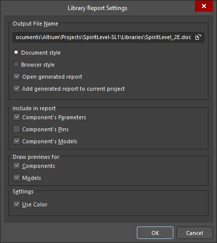
ライブラリレポート設定ダイアログのオプションとコントロール
出力ファイル名
- 出力ファイル名 - パスを含む出力ファイル全体を表示します。ブラウズフォルダアイコンを使用して、異なる場所と名前を検索して選択します
- ドキュメントスタイル - ファイル拡張子は.docで、ライブラリレポートのワードドキュメント形式が生成されます。
- ブラウザスタイル - ファイル拡張子は.htmlで、インターネットブラウザでウェブページが生成されます。必要に応じて出力ファイル名全体を編集できます。
- 生成されたレポートを開く - MS Wordまたはインターネットブラウザで生成されたレポートを開くように設定します。
- 生成されたレポートを現在のプロジェクトに追加する - 生成されたレポートを現在のプロジェクトに追加するように設定します。
レポートに含める
- コンポーネントのパラメータ - レポートにコンポーネントのパラメータを含めるように設定します。
- コンポーネントのピン - レポートにコンポーネントのピンを含めるように設定します。
- コンポーネントのモデル - レポートにコンポーネントのモデルを含めるように設定します。
プレビューを描画する
- コンポーネント - レポートのコンポーネントに対してプレビューを描画するように設定します。
- モデル - レポートのモデルに対してプレビューを描画するように設定します。
設定
- 色を使用する - ライブラリレポートがワードまたはウェブドキュメントで色の要素を含むように設定します。
-
レポート設定を構成してからOKをクリックします。生成後にレポートを開くように設定している場合、Docスタイルのレポートを生成する場合はMicrosoft Word、HTMLスタイルのレポートを生成する場合はデフォルトのブラウザがあれば、それが実行されます。
生成後に生成されたレポートをプロジェクトに追加するように選択した場合、それはプロジェクトパネルのGenerated\Documentsサブフォルダ(HTMLスタイルのレポートの場合)、またはGenerated\Text Documentsサブフォルダ(Docスタイルのレポートの場合)に表示されます。
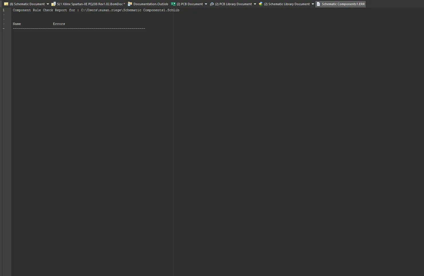
コンポーネントルールチェッカー
コンポーネントルールチェッカーは、重複やピンの欠落などのエラーをテストします。
-
レポート » コンポーネントルールチェック(ショートカット R, R)を選択して、ライブラリコンポーネントルールチェック ダイアログを開きます。チェックしたい属性を設定してからOKをクリックします。
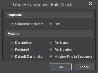
ライブラリコンポーネントルールチェックダイアログのオプションとコントロール
[]
重複
- コンポーネント名 – 重複したコンポーネント名をチェックするにはこのオプションを有効にします。
- ピン – 重複したピンをチェックするにはこのオプションを有効にします。
不足
- 説明 – 説明が不足している場合にチェックするにはこのオプションを有効にします。
- フットプリント – フットプリント名が不足している場合にチェックするにはこのオプションを有効にします。
- デフォルト指定子 – デフォルト指定子が不足している場合にチェックするにはこのオプションを有効にします。
- ピン名 – ピン名が不足している場合にチェックするにはこのオプションを有効にします。
- ピン番号 – ピン番号が不足している場合にチェックするにはこのオプションを有効にします。
- シーケンス内の不足ピン – シーケンス内のピンが不足している場合にチェックするにはこのオプションを有効にします。
-
ルールチェックに違反するコンポーネントをリストした<libraryname.ERR>というタイトルのレポートが設計スペースに表示されます。
- 必要に応じてライブラリを調整し、レポートを再実行してください。
- 回路図ライブラリを保存します。レポートを閉じて、回路図エディタの設計スペースに戻ります。
コンポーネントのピンからモデルへのリンクは、コンポーネントルールチェッカーによってチェックされません。しかし、このレベルのリンクは、ライブラリパッケージが統合ライブラリにコンパイルされるときにチェックされます。コンパイルされた統合ライブラリを使用する予定がない場合でも、ライブラリパッケージを使用してライブラリを作成および管理することは有益です。 レポートはライブラリドキュメントと同じ場所に保存され、プロジェクトパネルのDocumentation\Text Documentsサブフォルダーの下に自由文書として追加されます。 重複するピンをチェックする場合、各コンポーネントについて最初のインスタンスのみが報告されます。複数の重複が存在する場合でも、これらは別々に報告されません。
アクティブな回路図シンボルに対してコンポーネントレポートを生成できます -
詳しくはこちら。
他のソースからのコンポーネントのコピー
他のライブラリからのコンポーネントの移動とコピー
他の開かれている回路図ライブラリからあなたの回路図ライブラリにコンポーネントをコピーし、必要に応じてそのプロパティを編集することもできます。コンポーネントが統合ライブラリの一部である場合、.IntLibファイルを開いて、ソースライブラリを抽出するためにはいを選択する必要があります。その後、プロジェクトパネルから生成されたソースライブラリ(*.SchLib)を開きます。
-
Design Item ID リストで移動またはコピーしたいコンポーネントを選択し、それが設計ウィンドウに表示されるようにします。SCHライブラリパネルを参照してください。

-
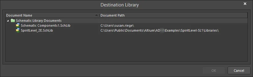
ツール » コンポーネントの移動またはツール » コンポーネントのコピーを選択して、現在開いているすべての回路図ライブラリドキュメントをリストアップする宛先ライブラリダイアログを開きます。開いているすべてのライブラリが、現在のプロジェクトや他の開いているプロジェクトの一部であるかどうかに関わらず、ダイアログにリストされます。
-
コンポーネントを移動/コピーしたいドキュメントを選択し、OKをクリックします。コンポーネントまたはそのコピーがターゲットライブラリに配置され、必要に応じて編集できます。
コンポーネントをコピーする場合、現在のライブラリをターゲットライブラリとして選択できます。既存のコンポーネントとグラフィカルな表現が似ており、わずかな修正のみが必要な新しいコンポーネントを作成したい場合に、同じライブラリにコンポーネントをコピーすると便利です。
回路図からのコンポーネントのコピー
回路図のシートから回路図ライブラリにコンポーネントをコピーし、必要に応じてそのプロパティを編集することもできます。回路図のシート上でコピーしたいコンポーネントを選択し、選択したコンポーネントの右クリックメニューからコピーコマンドを使用してコピーします(ショートカット:Ctrl+C)。次に、目的の回路図ライブラリを開き、SCH Libraryパネルのコンポーネントリスト領域で右クリックし、貼り付けを選択します(ショートカット:Ctrl+V)。
接続されたワークスペースまたはManufacturer Part Searchパネルから回路図シートに配置されたコンポーネントの場合、ソースワークスペースへのリンクが残ります。これらのコンポーネントは、SCH Libraryパネルで アイコンによって区別されます。開いているライブラリ内のすべてのコンポーネントのワークスペースリンクをクリアするには、メインメニューからツール » サーバーリンクのクリアコマンドを選択します。コマンドを起動すると、Confirm Clear Vault Linksダイアログが開きます。はいをクリックして、ダイアログで指定されたワークスペースリンクをクリアし、ライブラリを保存します。いいえをクリックして、何もせずにダイアログから終了します。
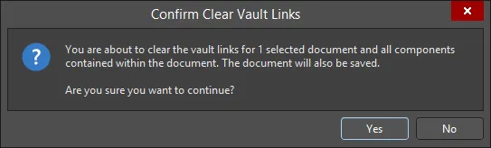
「Confirm Clear Vault Links」ダイアログ
複数コンポーネントのコピー
SCHライブラリパネルを使用して、複数のコンポーネントをコピーすることもできます。パネル内のコンポーネントを標準のCtrl+クリックまたはShift+クリック機能を使用して選択し、選択したコンポーネントの1つを右クリックして、ポップアップメニューからコピーを選択します。その後、リスト内で右クリックして以下の操作を行うことができます:
- 同じライブラリにコンポーネントを貼り付けます。
- 別の開いているライブラリにコンポーネントを貼り付けます。
- 同じ技術を使用して、回路図から開いているライブラリにコンポーネントをコピー&ペーストします。
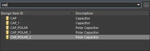
同じライブラリに貼り付ける場合や、コピーしたコンポーネントを別のライブラリに複数貼り付ける場合、コンポーネントは複製されますが、コンポーネント名は同じにはなりません。代わりに、各コピーには接尾辞が付きます。例えば、元のコンポーネントがCAPと呼ばれている場合、最初のコピーはCAP_1、2番目はCAP_2などと呼ばれます。
設計をある場所から別の場所へ移動する
ライブラリから設計にコンポーネントが配置されると、そのドキュメントがソースライブラリが存在しなくても、またはロードされていなくても、どこでも開けるように、設計ファイルにキャッシュされます。これは、設計をある場所から別の場所に移動する際に、ライブラリを移動する必要がないため便利です。なお、配置されたコンポーネントのプロパティ内には、元のソースライブラリ名とモデル名も保存されます。
SCHライブラリパネル
SCHライブラリパネルを使用すると、アクティブな回路図ライブラリドキュメントに格納されているコンポーネントを表示し、変更を加えることができます。このパネルでは、ライブラリのコンポーネントに加えた変更を回路設計ドキュメントに直接反映させる機能や、コンポーネントのモデルリンクを定義する機能も提供されています。

対話的に回路図ライブラリコンポーネントとそのピンを閲覧、表示、編集します。
ライブラリの閲覧
リスト内のコンポーネントエントリをクリックすると、それがデザインエディタウィンドウ内のアクティブな部品になります。デザインエディタウィンドウは編集可能であり、コンポーネントのシンボルを変更したり、必要に応じてコンポーネントにリンクされたモデルを追加、編集、または削除できます。ピンオブジェクトをパネルで選択すると、エディタワークスペース内の対応するグラフィカルオブジェクトが強調表示(およびズーム)されます。このようにして、SCHライブラリパネルは、回路図ライブラリコンポーネントとピンを素早く簡単に閲覧、表示、アクセスする方法を提供します。
コンテンツのフィルタリング
コンポーネントリストの内容はフィルタリングでき、ライブラリ内の特定のコンポーネントをすばやく見つけることができます。これは、ライブラリに多数のアイテムが含まれている場合に特に便利です。フィルタリングは、以下のセクションで説明されている方法のいずれかを使用して適用できます。
間接フィルタリング
このフィルタリング方法は、パネルの上部にある検索フィールドを使用してリストの内容をフィルタリングします。フィールドに入力された内容に基づいて名前マスキングが適用されます。エントリの範囲に対象とされるリスト内のコンポーネントのみが表示されたままになります。
すべてのライブラリコンポーネントフットプリントを再度リストにするには、検索フィールド内のエントリをクリア(削除)します。
フィルタリング機能は大文字と小文字を区別せず、「タイプアヘッド」機能をサポートしています。つまり、コンポーネントリストの内容は、入力すると同時にフィルタリングされます。
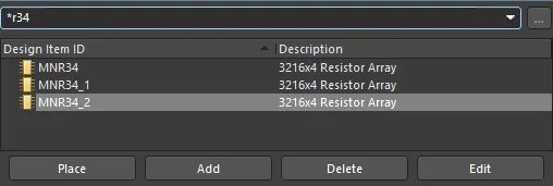
より複雑なフィルタリングには*ワイルドカード演算子を使用します。たとえば、MN*と入力すると、名前がMNで始まるコンポーネントフットプリントのみが表示されます。また、下の画像のように*r34と入力すると、名前の本体にR34が含まれるコンポーネントフットプリントのみが表示されます。
直接フィルタリング
この方法はパネルのすべての領域で利用可能であり、リストの領域内で直接入力することにより、エントリにすばやくジャンプできます。マスキングは適用されず、リストの完全な内容が常に表示されます。
コンポーネントフットプリントをすばやく見つけるためにこの機能を使用するには、パネルのコンポーネントセクション内をクリックしてから、ジャンプしたいコンポーネントフットプリントの最初の文字を入力します。たとえば、Rで始まるコンポーネントエントリにすばやくジャンプしたい場合は、キーボードでRを押します。リストでRで始まる最初のコンポーネントがアクティブになります。
特にライブラリが特に大きい場合、同じ文字で始まる複数のデザインアイテムIDがある場合は、特定のエントリをターゲットにするために追加の文字を入力します。たとえば、resと入力して、リストのRESシリーズの最初のものを強調表示します。

異なる開始文字を入力するために現在のフィルタリングをクリアするには、Escを押します。Backspaceキーを使用して、以前に入力されたフィルタ文字を順番にクリアします。
組み合わせフィルタリング
場合によっては、間接フィルタリングと直接フィルタリングを同時に使用すると便利な場合があります。たとえば、探しているコンポーネントがサブタイプのバリアントBRMZを持ち、プレフィックスがAD74であることがわかっている場合、この情報を間接(マスク)および直接エントリとして使用できます。
