在设计捕获阶段,实际要安装到电路板上的器件会以原理图符号表示;在板级设计阶段,则以 PCB 封装(footprint)表示。Altium Designer 元件可以:
封装可以从 PCB 编辑器复制到 PCB 库中、在不同 PCB 库之间相互复制,或使用 Footprint Wizard 或绘图工具从零开始创建。
创建新的 PCB 库
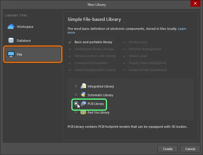
要创建新的 PCB 库,请从主菜单中选择 File » New » Library 命令,并在 New Library 对话框的 File 区域中选择 PCB Library 选项。
单击 Create 后,将创建一个名为 PcbLib1.PcbLib 的新 PCB 库文档,并在 Projects 面板中显示,同时会显示一个名为 PCBComponent_1 的空组件工作表。
库的内容显示在 PCB Library panel中。
现在,您可以使用 PCB 封装编辑器命令在新的 PCB 库中添加、删除或编辑封装组件。
从 PCB 文档创建 PCB 库
如果您已有一个 PCB 设计,并且所有封装都已放置到板上,则可以在 PCB 编辑器中使用 Design » Make PCB Library 命令生成一个仅包含这些封装的 PCB 库。 如果您希望为已完成的设计创建一个完全可用的精确库,或对其进行归档,这将非常有用。
启动该命令后,将自动创建一个库文档(<PCBDocumentName>.PcbLib)(并存储在与其来源 PCB 文档相同的位置),并将其添加到工程中。创建的文件会作为工程的一部分显示在 Projects 面板中,位于 Libraries\PCB Library Documents 子文件夹下。该文档将作为 PCB 封装编辑器中的活动文档打开。随后,PCB 上检测到的每一种唯一 PCB 元件都会被添加到该库中。
创建新的 PCB 封装
在一个 PCB 库中可以创建任意数量的 PCB 封装。要在现有库中创建新的 PCB 封装,可从主菜单选择 Tools » New Blank Footprint 命令;或在设计空间中右键并从上下文菜单选择 Tools » New Blank Footprint 命令;或在 PCB Library panel 的 Footprints 区域中右键,然后从上下文菜单选择 New Blank Footprint 。
由于新建库始终包含一个空的 PCB 封装,您也可以通过重命名 Component_1 来开始创建封装。为此,请在面板的 Footprints 列表中选择 PCBComponent_1,然后单击面板中的 Edit 按钮,或双击 PCBComponent_1 以在 Properties 面板的 Library Options 模式下打开 Footprint 选项卡。 在 Name 字段中输入能唯一标识该封装的新封装名称。
要从当前 PCB Library 文档中移除活动封装,请从主菜单选择 Tools » Remove Footprint 命令,或在设计空间中右键并从上下文菜单选择 Tools » Remove Footprint 命令。 启动命令后,会出现确认对话框,询问是否继续删除。单击 Yes 后,封装将从库文档中移除,并使 Footprints 列表中的上一个封装成为活动项。 也可以直接在 PCB Library panel中删除一个或多个库封装。在 Footprints 列表中选择所需封装,然后右键并从上下文菜单选择 Delete 命令。将出现确认对话框,询问是否继续删除 n 个封装。单击 Yes 后,封装将从库文档中移除,并使 Footprints 列表中的下一个封装成为活动项。
使用 IPC Footprint Batch Generator 创建封装
除了 Creating a PCB Footprint 页面中描述的技术外,还可以使用 IPC Footprint Batch Generator 在多个密度等级下生成多个封装。该生成器从 Excel 电子表格或逗号分隔文件中读取电子元件的尺寸数据,然后应用 IPC 方程来构建真正符合 IPC 标准 7351 修订版 B 的 PCB 封装 - Generic Requirements for Surface Mount Design and Land Pattern Standard。
批量生成器可创建以下封装类型: BGA, BQFP, CAPAE, CFP, CHIP, Chip Array, CQFP, DFN, DIP, DPAK, FM, LCC, LGA, MELF DIODE/RESISTOR, MOLDED CAP/IND/DIODE, PLCC, PQFN, PQFP, PSON, QFN, QFN-2ROW, SIP, SODFL, SOIC, SOJ, SON, SOP, SOT143/343, SOT223, SOT23, SOT89, SOTFL, WIRE WOUND,以及 ZIP。
对 IPC Footprints Batch Generator 的支持包括:
-
在 Altium Designer 安装目录的
\Templates 文件夹中包含封装类型的空白模板文件。
-
封装输入文件可包含单一封装类型的一个或多个封装信息,并且可以是 Excel 格式或逗号分隔(CSV)格式文件。
从主菜单选择 Tools » IPC Compliant Footprints Batch Generator 命令以打开 IPC Compliant Footprints Batch Generator 对话框。 使用该对话框添加需要处理的封装包文件,并按需设置生成选项。

IPC Footprints Batch Generator 提供选项,可在打开的 PCB 封装库中创建所有封装,或基于输入文件或封装名称生成单个库。
流程概述如下:
-
将要处理的文件添加到列表中。这些文件可以是基于 Excel 的,也可以是基于 CSV 的。使用 Add Files/Remove Files 按钮来整理列表,或直接将文件拖放到列表区域。
-
指定生成输出的输出文件夹(如果流程中需要生成新的 PCB Library 文件)。
-
使用选项来确定封装的生成方式。可以在活动 PCB Library 文档中生成所有封装。或者,为每个输入文件生成一个 PCB Library 文档(名称与输入文件相同),或为每个封装名称生成一个 PCB Library 文档(名称使用文件中指定的 FootprintName 字段;若该字段为空,则使用 IPC 命名)。生成的库文件将按照指定的 Output Folder进行存储。
-
可选:生成基于 HTML 的报告(并可选在处理完成后自动打开)。报告会列出日期、时间和处理耗时,以及所有已处理文件和相关的致命错误、错误与警告。
-
如果您选择生成新的 PCB 库,也可以选择在生成完成后自动打开这些库。
在按需定义要处理的文件列表及其他所有选项后,单击 Start。处理将开始进行,进度会在对话框中显示。您可以随时单击 Stop 或 Close 取消。所有封装生成完成后,单击 Close 退出对话框,并享受生成器劳动的成果。
Options and Controls of the IPC Footprints Batch Generator Dialog
-
Text Box - 要处理的文件列表。
-
Open Template - 单击以打开 Open Template 对话框,然后从下拉列表中选择模板类型。单击 OK 以打开当前数据集所对应的底层 Excel 模板。
你也可以使用向下箭头访问所有可用模板类型的列表。从列表中选择所需的模板类型,以打开对应的 Excel 模板。
每种封装类型的模板可在 \ProgramData\Altium\Altium Designer <Globally Unique Identifier>\Extensions\IPC Footprint Generator\Templates 中找到。每个模板的 Data 选项卡包含封装规格。使用 Legend - Package 选项卡查看模板中 Data 选项卡所用的封装数据字段说明。使用 Legend - Footprint 选项卡查看模板中 Data 选项卡所用的封装焊盘(footprint)规格字段说明。
-
Help On - 单击以打开 Help On 对话框,然后选择模板类型以访问参考信息,或使用下拉列表选择所需的封装类型。
-
Add Files - 单击以选择封装输入文件,将输入的封装类型文件添加到文本框中。
-
Remove Files - 单击以移除文本框中选定的文件。
-
Output Folder - 使用浏览按钮搜索并设置所需的输出位置。
-
Produce STEP model - 启用以生成 STEP 模型。
-
Model Folder - 使用浏览按钮搜索并选择所需模型的位置。
-
Generate all footprints in - 启用以生成当前 PCB Library 中的所有焊盘(footprint)。
-
Generate single PcbLib files per input file - 勾选后,将在输出文件夹中生成一个与正在处理的输入文件同名的 PCB Library 文件。该文件中的焊盘(footprint)将被添加到 PCB Library 中。
-
Generate single PcbLib files per footprint name - 勾选后,将为输入文件中的每个封装在输出文件夹中生成一个 PCB Library 文件。
-
Generate report on completion - 勾选后,在完成时生成报告。
-
Open generated PcbLib files on completion - 勾选后在完成时打开生成的 PCB Library 文件。仅当 Generate single PcbLib files per input file 被勾选时,此选项才可用。
-
Processing - 显示批量生成过程进度的进度条。
-
Start/Stop - 单击 Start 启动批量生成。使用 Start 按钮后,它会变为 Stop;单击 Stop 可停止批处理过程。
-
Close - 单击以停止批处理过程并关闭对话框。
-
对于具有较大散热焊盘(尺寸为 2.1mm x 1.6mm 或更大)的封装,钢网开口(paste mask)会被拆分为多个小填充区域。
-
对于涉及海鸥翼引脚(gullwing leads)的封装,会对焊盘进行修剪,以防焊盘延伸到封装本体下方。
-
对于带有较大中心散热焊盘的小型封装(PQFP、 QFN、 SOIC 和 SOP),会修剪外围焊盘,以确保焊盘之间满足 IPC 标准要求的间隙。
-
向导中输入的所有尺寸均使用公制(mm)单位。
-
请参考底层 Excel 模板中的图例(可从 IPC Compliant Footprints Batch Generator 对话框中的 Open Template 菜单访问),以获取各受支持封装的当前数据集。对于默认安装的 IPC Footprint Generator 扩展,封装类型文件的模板位于以下文件夹中:
Altium Designer Develop / Altium Designer Agile: \ProgramData\Altium\Altium Designer <Solution> <GUID>\Extensions\IPC Footprint Generator\Templates
Altium Designer: \ProgramData\Altium\Altium Designer <GUID>\Extensions\IPC Footprint Generator\Templates
请以这些模板为基础创建封装文件,并将其“输入(feed)”到生成器中。
-
要快速生成单个符合 IPC 的焊盘(footprint),请使用 IPC Compliant Footprint Wizard。
从其他来源添加焊盘(Footprint)
可以从其他 PCB 库中复制 PCB 元件,然后在目标库中重命名并修改,以满足所需规格。实现该功能有多种方式。
-
在 PCB 文档中选择已放置的焊盘(footprint),然后复制(Edit » Copy)并使用 Edit » Paste Component 将其粘贴到已打开的 PCB 库中。 如果从 PCB 编辑器向剪贴板复制了多个元件,则它们都会作为独立的元件焊盘(component footprint)粘贴到库文档中。
-
当要复制的焊盘(footprint)在 PCB Library Editor 中处于活动状态时,选择 Edit » Copy Component,切换到已打开的目标 PCB 库,然后选择 Edit » Paste Component。
-
在 PCB Library panel 中使用标准的 Shift+Click 或 Ctrl+Click 选择列表中的一个或多个焊盘(footprint),右键单击并选择 Copy。切换到目标库,在焊盘名称列表中右键单击并选择 Paste
n Components,其中 n 为元件数量。
如果同一元件被多次粘贴到库中,会通过后缀 DUPLICATE 或 DUPLICATEn 进行高亮标识;当存在多个重复项时,n 表示重复项的编号。
请注意,如果该元件是从已连接的 Workspace 或从 Manufacturer Part Search 面板放置到 PCB 上的,则会保留到源 Workspace 的链接。你可以通过主菜单中的 Tools » Clear Server Links 命令清除当前打开库中所有元件的 Workspace 链接。 启动该命令后,会打开 Confirm Clear Vault Links 对话框。单击 Yes 清除对话框中指定的 Workspace 链接并保存库;单击 No 退出对话框且不执行任何操作。
剪贴板可以存储多种对象,这些对象可被添加(粘贴)到 Altium Designer 中的各种文档类型。剪贴板支持多种数据格式,具体取决于来源和对象类型,并且可设置为仅存储在 Altium Designer 环境内复制或剪切的对象,或使用整个 Windows 剪贴板——通过
Preferences 对话框的
System - General page 中的
Monitor clipboard content within this application only 选项进行设置。请注意,并非每个设计编辑器都支持所有数据类型,不受支持的对象将不会被粘贴。
检查焊盘(Footprint)并生成报告
为检查新焊盘是否正确创建,可以生成多种报告。
Library List
要生成列出当前 PCB Library 文档中所有 PCB 焊盘(footprint)的报告,请从主菜单选择 Reports » Library List 命令。 启动该命令后,报告将以 <PCBLibraryDocumentName>.REP 的形式生成在源 PCB Library 文档所在的同一文件夹中,并会自动在主设计窗口中作为活动文档打开。该报告汇总库中元件模型的总数,并按名称列出所有元件模型。
该报告将作为自由文档添加到 Projects panel 中,并位于 Documentation\Text Documents 子文件夹下。
Library Report
你可以从当前活动库文档生成一份报告,其中包含该库内存储的元件信息。报告可配置为包含元件预览图(彩色绘制或保持黑白)。报告可生成为 Microsoft Word 文档(*.doc),或标准 HTML 文档(*.html)。
从主菜单选择 Reports » Library Report 命令以打开 Library Report Settings 对话框。使用该对话框配置报告的内容与样式,以及报告生成的位置(及文件名)。默认情况下,报告将以 PCB 库命名,并存储在相同位置。

Library Report Settings 对话框
Options and Controls of the Library Report Settings Dialog
输出文件名
-
Output File Name - 显示完整的输出文件(含路径)。使用浏览文件夹图标搜索并选择不同的位置和名称
-
Document style - 文件扩展名将为 .doc,并将为库报告生成 Word 文档格式。
-
Browser style - 文件扩展名将为 .html,并将在互联网浏览器中生成网页。 如有需要,你可以编辑完整的输出文件名。
-
Open generated report - 启用后,可在 MS Word 或互联网浏览器中打开生成的报告。
-
Add generated report to current project - 启用后,将生成的报告添加到当前项目。
绘制元件预览图
启用后,在报告中为元件绘制预览图。
设置
-
Use Color - 启用后,允许库报告在 Word 或 Web 文档中包含彩色元素。
单击 OK 后将生成报告。如果你选择在生成后打开报告,则在你的计算机上安装了 Microsoft Word(生成 Doc 样式报告时)或 Microsoft Internet Explorer(生成 HTML 样式报告时)的情况下,将会自动打开。
如果你选择在生成后将报告添加到项目中,它将出现在 Projects panel 的 Generated\Documents 子文件夹下(HTML 样式报告),或出现在 Generated\Text Documents 子文件夹下(Doc 样式报告)。
Component Rule Checker
要验证活动库中的所有元件,PCB 封装编辑器提供了“元件规则检查(Component Rule Checking)”功能。该功能提供多项检查,包括检查重复图元、缺失焊盘标号、悬空铜皮 以及不恰当的元件参考标号。检查结果会生成一份基于文本的报告,列出所有违反这些检查的项目。要运行元件规则检查:
-
保存你的库文件。
-
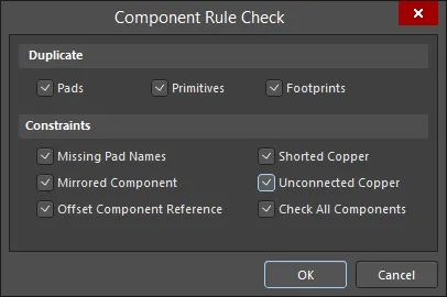
选择 Reports » Component Rule Check(快捷键 R、R)以打开 Component Rule Check 对话框。
-
勾选所有可用的复选框,然后单击 OK。将生成一份名为
<LibraryName>.ERR 的报告,并在文本编辑器中打开。任何错误都会被标注出来。每个被发现有错误的元件封装都会被列出,并附带其未通过的具体测试项。
-
关闭报告以返回 PCB 封装编辑器。
可以为当前活动的 PCB 封装生成一份元件报告(Component Report)—
了解更多。
更新 PCB 封装
从 PCB 库更新 PCB 封装有两种方式:“从 PCB 库推送(Push)”PCB 封装,或在 PCB 编辑器中“拉取(Pull)”。推送 PCB 封装更新会从 PCB 库中取出所选封装,并用它来更新所有打开且包含该封装的 PCB 文档。当需要完全替换时,第一种方法是最佳选择。第二种方式允许你在执行更新前查看现有封装与库中封装之间的所有差异。你还可以选择要从库中更新哪些对象。当你需要弄清楚板上封装与库中封装到底改了什么时,第二种方法是最佳选择。
从 PCB 库推送封装更新
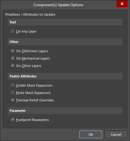
在 PCBLIB 编辑器中,使用 Tools » Update PCB with Current Footprint (当你希望将更改传递到 PCB 文档的封装为活动封装时)或 Tools » Update PCB With All Footprints 命令。在 PCB Library 面板中,在 PCB Library 面板的 Components 区域右键,然后选择 Update PCB with [Component] 或 Update PCB with All。运行这些命令会打开 Component(s) Update Options 对话框,你可以在其中选择要更新的图元/属性。使用该对话框来确定要更新封装的哪些方面。单击 OK 后,所有打开的 PCB 文档中该封装的所有已放置实例都会根据指定的更新选项,应用所做的更改并完成更新。
所选更新将被推送到所有打开的 PCB 文档中与之对应的封装(不论它们属于哪个工程)。
从 PCB 编辑器拉取封装更新
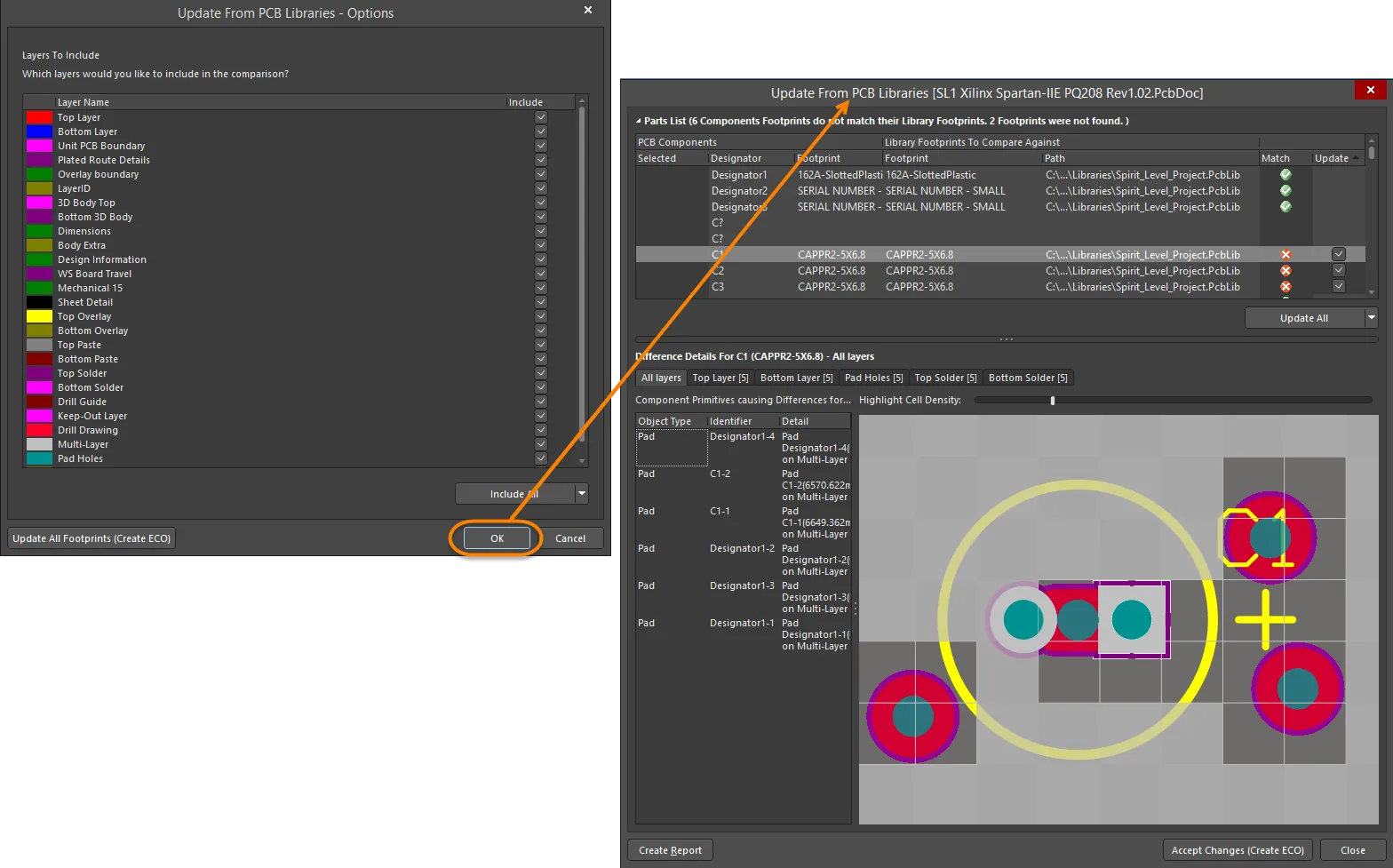
在 PCB 编辑器中,使用 Tools » Update From PCB Libraries 命令,该命令会打开 Update From PCB Libraries - Options。单击 OK 以打开 Update From PCB Libraries 对话框。
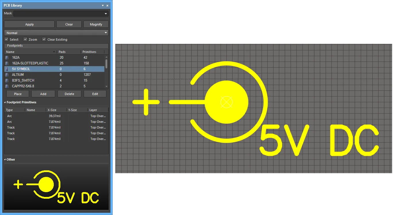
PCB Library 面板
PCB Library 面板使你能够浏览活动 PCB 库文档中存储的封装并编辑其属性。当 PCB Library 文档处于活动状态时,该面板会填充与该库中各个封装相关的信息。该面板还支持将对封装所做的任何更改直接传递到 PCB 设计文档。

PCB Library 面板
PCB Library Panel Content and Use
库浏览
该面板包含三个主要区域,每个区域都提供对活动 PCB 库中封装的不同范围或视图:
-
封装 - 活动库中的封装列表。每个条目都会列出用于定义该封装的焊盘数量和图元对象数量。
-
Footprint Primitives - 构成当前所选封装的图元对象 及其主要属性。
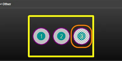
-
Other - 当前所选封装的简化整体视图,并通过叠加图形指示主编辑器视图位置。
当在面板中选择某个封装时,其组成图元会填充到 Footprint Primitives 区域中,同时该封装会显示在主编辑器设计空间中。在面板中选择某个图元对象,会使编辑器设计空间中对应对象高亮显示。通过这种方式,PCB Library 面板提供了一种快速、便捷的方式来浏览、查看和访问 PCB 库封装。
双击 Footprint 条目会打开 Properties 面板以查看/编辑 封装属性;双击 Footprint Primitives 条目将访问其对应的 Properties 面板——更多选项请参见下方 右键菜单 部分。
筛选内容
列表内容可进行筛选,使你能够在库中快速找到特定封装。如果库包含大量条目,这一点尤其有用。可通过以下方法进行筛选:
间接筛选
该方法使用面板顶部的 Mask 字段来筛选列表内容。会根据该字段中的输入应用掩码(Mask)。只有被该输入范围命中的封装才会继续显示在列表中。
注意 Mask 字段不区分大小写。要再次列出所有封装,请清空(删除)Mask 字段中的内容。
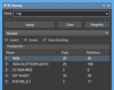
使用 * 通配符运算符可实现更复杂的筛选。例如,输入 m* 将只显示名称以 m 开头的封装;或者如下图所示,输入 *16 将只显示名称中包含 16 的封装。
直接筛选
该方法适用于面板中的所有列表区域,允许你在列表区域内直接键入以快速跳转到某个条目。该方法不会应用掩码,因此列表的全部内容始终可见。
要使用该功能快速查找封装,请在面板的 封装 区域内单击,然后键入你要跳转到的封装名称的首字母。例如,如果你想快速跳转到以字母 S 开头的封装条目,你可以在键盘上按下“S”。列表中第一个以 S 开头的封装将被设为活动项,并且该字母会被高亮显示,以表明列表的筛选基于它。
如果有多个封装以同一字母开头,尤其当库非常大时,可继续输入更多字母以定位到所需的特定条目,例如如下所示的“SO”。

要清除当前筛选以便输入不同的起始字母,请按 Esc。使用 Backspace 键可按顺序清除先前输入的筛选字符。
组合筛选
在某些情况下,同时使用间接筛选与直接筛选会很有帮助。例如,如果你记得要找的封装子类型编号为 4,前缀为 PO,则可将这些信息分别作为间接(掩码)与直接输入来使用。
封装控制
-
Place - 单击以放置所选封装。
-
Add - 单击以向列表添加新封装。默认名称将为
PCBCOMPONENT_1.
-
Delete - 单击以删除所选封装。删除前会弹出对话框要求确认。
-
Edit - 单击以打开 Properties panel,编辑所选封装的属性。
浏览封装图元
Footprint Primitives 区域 列出当前在 封装 列表中所选封装的所有组成图元对象。对于每个图元条目,会显示以下信息:
-
Type - 图元对象类型(例如:焊盘、走线、圆弧等)。
-
Name - 对象标号的指定值(如果存在)。
-
X-Size - 对象的 X 尺寸(例如:圆弧、走线或填充的宽度,焊盘的 X-Size 值)。
-
Y-Size - 对象的 Y 尺寸(例如:填充的高度,焊盘的 Y-Size 值)。 对于走线或圆弧,该字段将为空。
-
Layer - 对象所在的层。
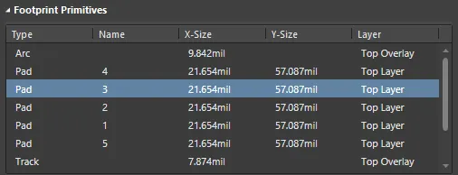
当在面板中选择单个对象图元时,编辑器设计空间中对应对象(走线、圆弧、焊盘等)会以图形方式高亮显示。
控制在设计空间中显示已浏览条目
在任一面板列表区域中选择条目都会应用筛选,本质上是将该条目作为筛选范围。设计编辑器窗口中文档的可视化筛选效果由面板顶部的一组高亮控制项决定。
-
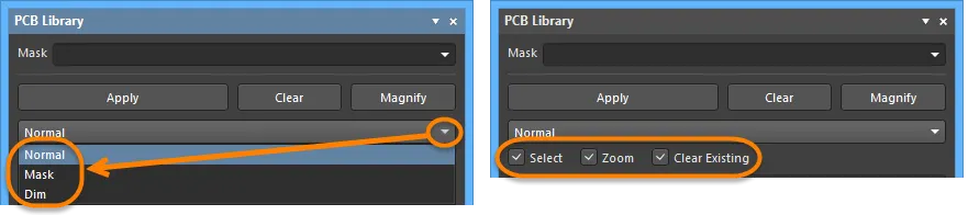
Mask / Dim / Normal - 提供用于在设计编辑器窗口中直观对比已过滤与未过滤对象的选项。遮罩与变暗的效果由 Highlighting Options 在 Preferences 对话框的 PCB Editor - Display 页面中设置决定。
-
当选择 Mask 时,已过滤对象将在设计编辑器窗口中保持可见,而所有其他对象将变为单色。应用此选项后,未过滤对象将无法被选择或编辑。
-
当选择 Dim 时,已过滤对象将在设计编辑器窗口中保持可见,而所有其他对象保留其颜色但会被加深/变暗显示。
-
Select - 启用时(默认),将会在设计空间中选中已过滤对象。
-
Zoom - 启用时(默认),将会在设计空间中对已过滤对象进行缩放并尽可能居中显示。
-
Clear Existing - 启用时(默认),在应用新过滤器之前会清除现有过滤器。禁用此选项可让你扩展现有过滤器,即在现有过滤器基础上再应用一个新过滤器,从而进一步细化过滤条件。
这些选项可以任意组合启用。例如,你可能希望将所有已过滤对象在设计空间中缩放、居中并选中,同时应用遮罩以减少其他设计对象带来的杂乱。使用 Clear 按钮可清除当前应用的过滤器。设计空间中的所有对象将完全可见,并可用于选择/编辑。如果你想重新应用过滤器,请单击 Apply 按钮。
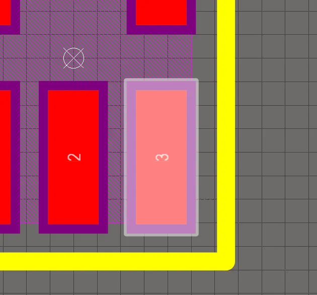
使用面板的迷你查看器
底部区域为该文档提供一个迷你查看器,其窗口中央显示活动封装的图像。设计编辑器窗口中当前显示的区域用白色哈希标记表示,如下图所示。
单击面板顶部的 Magnify 按钮,可在设计编辑器窗口中提供一个浮动放大镜和缩放光标。当你在设计空间中移动它们时,面板中的迷你查看器将显示以光标为中心的活动封装放大图像。这样你就可以在设计编辑器窗口中以全尺寸浏览文档,同时在迷你查看器窗口中查看放大细节。
使用 Page Up 和 Page Down 键增大或减小放大倍率。右键单击、单击或按 Esc 退出放大模式。
右键菜单
封装(Footprints)
-
New Blank Footprint - 选择以向列表添加一个新封装。该封装将被赋予默认名称 PCBCOMPONENT_1,并在设计编辑器窗口中打开一张空白工作区,供你开始放置用于定义该封装的基本图元对象。
-
Footprint Wizard - 单击以打开 Footprint Wizard。Wizard 的各页面将引导你完成创建新元件封装的步骤。
-
Cut - 将所选封装复制到 PCB Library Editor 的内部剪贴板,然后从库中永久删除该封装。将弹出确认对话框,要求确认是否继续删除。
-
Copy - 将所选封装复制到 PCB Library Editor 的内部剪贴板。
-
Copy Name - 将当前聚焦封装的名称复制到 PCB Library Editor 的内部剪贴板。
-
Paste - 将 PCB Library Editor 内部剪贴板中的封装粘贴到当前活动库文档中。该命令的条目会根据剪贴板上有效封装的数量而变化。
-
删除 - 从库文档中永久删除所选封装。将弹出确认对话框,询问是否继续删除。
-
Select All - 快速选中列表中的所有封装条目。
-
Footprint Properties - 单击以访问 Properties panel ,查看/修改当前聚焦封装的 Name、 Description、 Type、 Height、 Area 以及 Parameters 。当在面板中双击某个封装条目时,也会打开该封装的 Properties 面板。
-
Place - 将当前聚焦封装放置到 PCB 设计文档中。单击后,最近一次处于活动状态的 PCB(不论其属于哪个工程)将成为设计空间中的活动文档。
-
Update PCB With <FocusedFootprint> - 将库文档中对当前聚焦封装所做的更改传递到所有已打开且放置了该封装的 PCB 设计文档中。该封装的所有实例都会更新。
-
Update PCB With All - 将库文档中对封装所做的所有更改传递到所有已打开且放置了这些封装的 PCB 设计文档中。所有已放置的、发生更改的封装实例都会更新。
-
Report - 为活动封装生成报告。启动命令后,将在源 PCB 库文档所在文件夹中生成报告(
LibraryName.CMP),并会自动在设计编辑器窗口中作为活动文档打开。报告列出包括封装尺寸、构成封装的图元对象明细,以及它们所在的层等信息。
-
Delete All Grids And Guides In Library - 单击以删除该库的网格与参考线。
封装图元(Footprint Primitives)
-
Show Pads - 启用以显示焊盘条目。
-
Show Vias - 启用以显示过孔条目。
-
Show Tracks - 启用以显示走线条目。
-
Show Arcs - 启用以显示圆弧条目。
-
Show Regions - 启用以显示区域条目。
-
Show Component Bodies - 启用以显示元件本体条目。
-
Show Fills - 启用以显示填充条目。
-
Show Strings All - 启用以显示字符串条目。
-
Show Bond Wires - 启用以显示键合线条目。
以上列出的命令将取决于所选文档中的对象类型。也可能还会提供其他 Show 命令。
-
Select All - 快速选中列表中的所有封装图元条目。
-
Report - 在面板的 Footprints 区域为当前聚焦封装生成图元信息报告。启动命令后,将打开 Report Preview 对话框,其中包含当前在面板 Footprint Primitives 区域显示的图元信息。使用该对话框可查看、打印并以多种文件格式导出报告。
-
Properties - 访问当前聚焦图元对应的 Properties 面板,在其中按需查看并修改属性。当在面板中双击某个图元条目时,也会打开该图元对应的 Properties 面板。
注释
-
支持标准的 Ctrl+Click 和 Shift+Click 功能,用于在列表中选择多个条目。
-
活动封装是指其图形当前显示在设计编辑器窗口中的封装。封装可以处于活动状态,而不一定在 Footprints 列表中被选中和/或聚焦。
-
Ctrl+Click在列表中对已选条目执行
-
Ctrl+Click 操作可取消选择。如果该条目是该区域中唯一被选中的条目,执行此操作将清除过滤器。
-
可使用键盘快捷键 Home、 Down Arrow、 Up Arrow 和 End 以及设计空间 Tools 右键子菜单中的 First Component、 Next Component、 Previous Component 和 Last Component 命令,分别显示第一个、下一个、上一个以及最后一个封装。
-
在面板中存在多列数据的区域,可通过单击任意列的表头按该列排序。单击一次按升序排序;再次单击按降序排序。
-
你可以更改数据列的显示顺序。要移动某列,单击其表头并水平拖动到所需位置。出现两个位置箭头时表示该位置有效。
-
在浏览设计对象时应用的过滤是永久性的。如果选择了 Mask 或 Dim 高亮方式,所有不在过滤范围内的对象将在设计空间中变淡显示(取决于设置),并且无法被选择或编辑。在设计编辑器窗口内单击不会清除过滤器。必须在面板中单击 Clear 按钮来清除永久过滤器。
-
粘贴到活动库文档中的封装可以来自 PCB 设计文档或另一个 PCB 库文档。
-
如果从 PCB Editor 的主设计中将多个封装复制到剪贴板,则只会将该组中最后被选中的封装粘贴到库文档中。
-
如果同一封装在库中被粘贴多次,或在未重命名的情况下向库中添加了多个新封装,则这些副本将通过后缀 - DUPLICATE、- DUPLICATE1、- DUPLICATE2 等加以区分。
-
在使用 Place 命令放置库封装之前,必须先打开一个 PCB 设计文档。
-
要将库文档中对封装所做的更改传递出去,必须打开一个 PCB 设计文档。
-
创建新的 PCB 库文档时,默认情况下该面板将包含一个单独的空白封装 -
PCBCOMPONENT_1。
-
库封装只能在源 PCB 库(
*.PcbLib)中编辑。你无法编辑集成库(*.IntLib)中的封装。你需要先反编译集成库,然后在源 PCB 库文档中编辑所需封装。之后可重新编译源文件以生成更新后的集成库。

 AI 翻译
AI 翻译