xSignal 是由设计人员定义的、连接两个节点之间的信号路径;这两个节点可以位于同一网络内,也可以位于不同网络中。
xSignal 可通过以下方法来定义:
-
使用 xSignals Multi-Chip Wizard。这是创建 xSignal 最常用的方法,并在下文的 described below 中进行说明。
另外,也可以先选择感兴趣的对象,然后再选择相应命令来使用以下方法:
-
基于所选焊盘创建单个 xSignal。选择所需的起始焊盘和结束焊盘(如果存在串联端接器件,这些焊盘可以位于不同网络中)。焊盘可以在设计空间中直接选择,也可以在 PCB 面板的 Nets 模式下定位并选择焊盘(如下图所示)。选中焊盘后,可在设计空间中对某个已选焊盘右键,然后运行 xSignals » Create xSignal from Selected Pins 命令;或在 PCB 面板中对某个已选焊盘右键并运行 Create xSignal 命令。新建的 xSignal 将列在 PCB 面板的 xSignals mode of the PCB panel 中。
当你基于所选引脚(封装焊盘)来定义 xSignal 时,在运行 Create 命令之前,只选择起始焊盘和结束焊盘。
新 xSignal 的名称将由两个网络名组合而成,并用连字符连接。xSignal 名称可在 PCB 面板的 xSignals 模式中编辑。
可将新 xSignal 添加到某个 xSignal 类中;在面板的 xSignal Classes 区域右键以创建新类并向其中添加成员。
-
选择源器件,然后在所选器件上右键,并从上下文菜单中选择 xSignal » Create xSignals between Components command。将打开 Create xSignals Between Components 对话框,并已选中所选源器件。该对话框在下文的 described below 中说明。
-
在设计空间中选择一个或多个串联器件,然后在其中一个所选器件上右键,并从上下文菜单中选择 xSignal » Create xSignals from Connected Nets command。将打开 Create xSignals From Connected Nets 对话框。所选源器件以及连接到该器件的网络将被选中。该对话框在下文的 described below 中说明。
-
在某些情况下,你可能希望在现有 xSignal 内创建一个 xSignal;此时可使用 PCB 面板的 xSignal 模式。请确保面板顶部启用了 Select 选项,找到当前 xSignal,在面板的 xSignal Primitives 区段中选择所需焊盘,然后在设计空间中对其中一个所选焊盘右键,并使用本列表第 2 步所述的方法完成流程。

在面板的 Nets 模式中选择两个焊盘,对其中一个所选焊盘右键,然后选择 Create xSignal。注意,这些焊盘位于不同网络中。
如果起始焊盘和结束焊盘位于同一网络中,xSignal 将采用 <NetName>_PPn 的命名形式,其中 n 是用于区分该网络中定义的多个 xSignal 的下一个可用整数。如果起始焊盘和结束焊盘位于不同网络中,xSignal 将采用 <StartNet>_<EndNet>_PPn 的命名形式,其中 n 是用于区分该网络组合中定义的多个 xSignal 的下一个可用整数。
请注意,也可以使用
Constraint Manager 来创建 xSignal:
learn more。
xSignals Multi-Chip Wizard
xSignals Multi-Chip Wizard 用于在单个源器件与多个目标器件之间创建 xSignal。Wizard 采用面向器件的方法来识别潜在的 xSignal——你选择一个源器件、感兴趣的网络以及目标器件,随后 Wizard 会分析从源器件到指定器件的所有潜在路径,路径会穿过串联无源器件并沿着任何分支延伸。作为设计人员,你可以选择希望生成的 xSignal,并且在需要时还可以创建匹配长度(Matched Length)设计规则。Wizard 还可用于针对多种常见接口与存储器电路,自动创建 xSignal 和 xSignal 类。
在此 Wizard 中,输出引脚称为 Source,目标输入引脚称为 Destination。
该向导也是一个可多次运行的工具——从你在 xSignal Routes 页面最初创建的 xSignal 总主组中,你可以选择其中的一个子集,定义类与规则,然后返回主组,再选择另一个子集并为其定义类与规则,如此循环。
Wizard 的一大优势在于 Wizard 与 PCB 编辑器之间的协同操作非常便捷。在向导任意页面点击某个 xSignal,PCB 上对应的焊盘以及任何布线都会以可视方式高亮显示。
在当前阶段,该向导不支持自动添加 T 形结标识符(通常称为 tie-points 或 branch-points)。如果你的设计包含分支布线,建议你:
-
如果存在无源器件(例如串联端接电阻),先从源器件到无源器件进行长度调谐。
-
对每个分支进行长度调谐,从 T 形结到目标器件。
-
如有需要,再对无源器件(若无无源器件则从源端)到 T 形结之间的剩余长度进行调谐。
要访问 xSignals Multi-Chip Wizard,可从主菜单选择 Design » xSignals » Run xSignals Wizard 命令,或在 PCB 布局中右键然后选择 xSignals » Run xSignals Wizard。将显示向导的起始页面。

xSignals Multi-Chip Wizard
xSignals Multi-Chip Wizard Modes
在 Wizard 的第二页,你将被要求选择 Custom Multi-Component Interconnect、On-Board DDR3 / DDR4 或 USB 3.0。Custom Multi-Component Interconnect 模式用于在所选源器件与多个目标器件之间定义多个 xSignal;而 On-Board DDR3 / DDR4 模式用于为 DDR3 或 DDR4 存储器创建 xSignal。USB 3.0 模式会为每个 USB 3.0 通道创建 xSignal、xSignal 类以及匹配长度规则。请选择符合你需求的模式。
The Custom Multi-Component Interconnect Mode
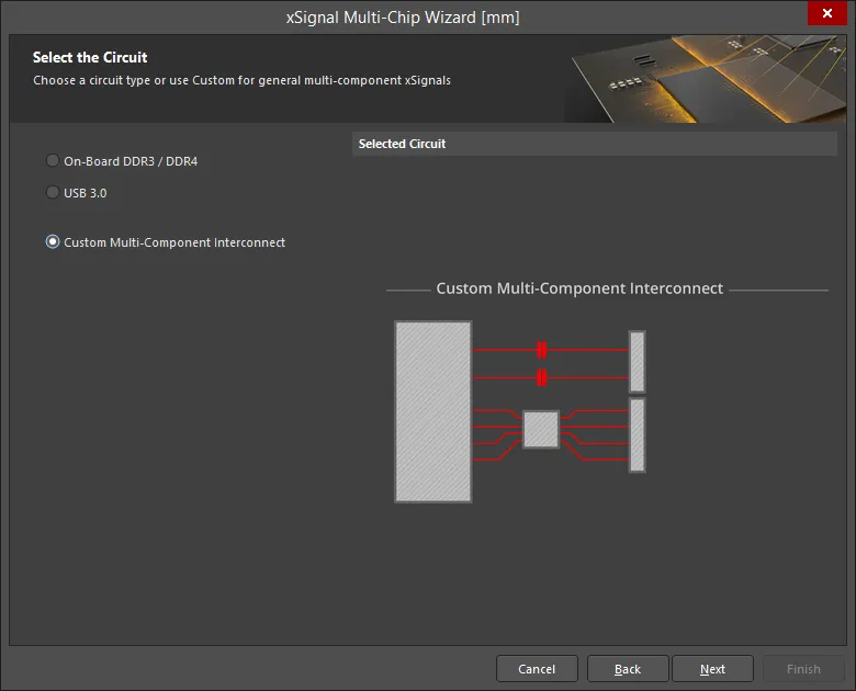
在该模式下,向导可用于在所选源器件与多个目标器件之间定义多个 xSignal。向导采用面向器件的方法来识别潜在 xSignal;你选择一个源器件、感兴趣的网络以及目标器件;随后它会分析从源器件到目标器件的所有潜在路径,路径会穿过串联无源器件并沿着任何分支延伸。作为设计人员,你可以选择希望生成的 xSignal。除了为器件之间多个网络定义端到端 xSignal 外,向导还允许你为这些端到端信号的各个区段创建 xSignal(从源输出引脚到串联端接器件,以及从串联端接器件到目标输入引脚)。根据你启用的设置,向导还可以创建 xSignal 类以及面向这些 xSignal 的 Matched Net Lengths 设计规则。向导完成后,你就可以开始长度调谐流程。
向导通过多个页面进行配置。页面数量取决于电路配置。例如,如果存在串联端接器,将在流程后续出现额外页面。下文将说明每个页面的配置。
选择源器件
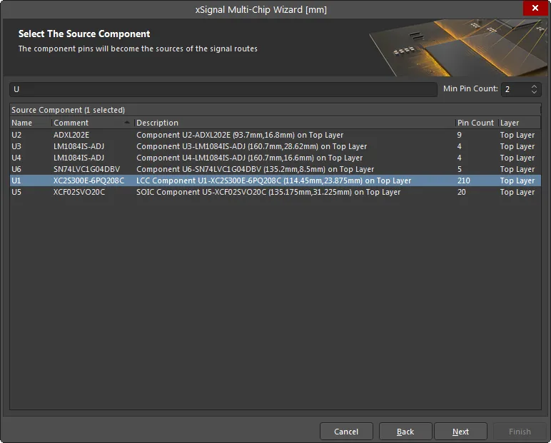
使用此页面选择单个源器件。使用表格顶部的 Filter 和 Min Pin Count 字段来帮助定位目标器件。支持 * 和 ? 通配符。
该向导中的表格支持右键快捷菜单,并支持标准 Windows 多选按键。你也可以使用左键单击或空格键来切换所选条目的复选框状态。
选择源网络
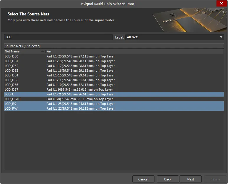
选择连接到所选源器件的感兴趣网络。使用表格顶部的 Filter 和 Label 字段来帮助定位目标网络。只有带有所列网络的引脚才会成为信号走线的源端。
选择目标器件
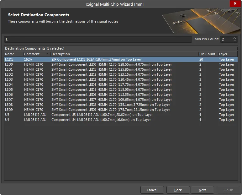
选择所需的目标器件。使用表格顶部的器件 Filter 和 Min Pin Count 字段来帮助定位目标器件。
当你点击 Next 时,向导将识别在所选器件之间、基于已选择网络集合可创建的所有可能 xSignal。如果向导检测到两引脚器件且其两个引脚都连接到所选网络,则会自动将其识别为串联端接器件,并在流程后续出现额外的向导页面。
xSignal Routes
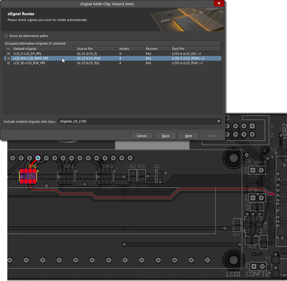
向导的此页面会列出从每个 Source Pin 到每个 Destination Pin 的建议 xSignal。点击某条目可在 PCB 上高亮显示该 xSignal。
在分析网络路径以识别潜在 xSignals 之后,向导会尝试缩小集合,只列出你感兴趣的组合。这些就是端到端的 xSignals;上图显示了它们位于向导前几页所选的源器件与目标器件之间。图中还显示向导在每条路径中都检测到了串联端接器件 RA1。RA1 实际上是一个四联电阻包——在这种情况下,向导会自动创建逻辑关联:假设每个电阻都跨接在电阻包的两端,它会将连接到该器件上彼此相对引脚的网络配对。
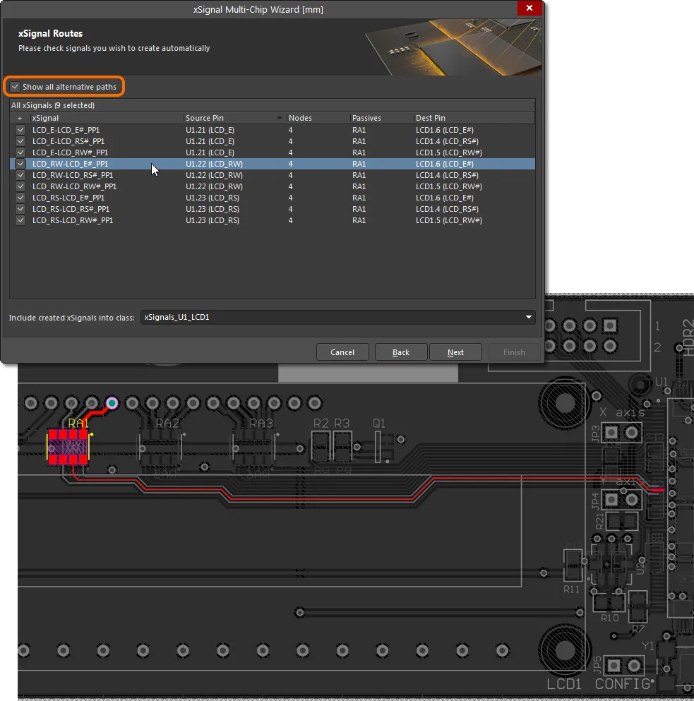
由于“每个电阻的两端引脚彼此相对”这一假设并不总是正确,你可以在 Dest Pin 列中使用下拉框选择其他可用的输出网络。或者,启用网格顶部的 Show all alternative paths 选项,以显示所有可用于生成 xSignals 的潜在网络组合。对你希望创建 xSignal 的每一行勾选复选框。已启用的 xSignals 将被添加到本页底部 Include created xSignals into class 字段中显示的类里。你可以输入一个新名称,或从下拉列表中选择一个。
xSignals 长度调谐
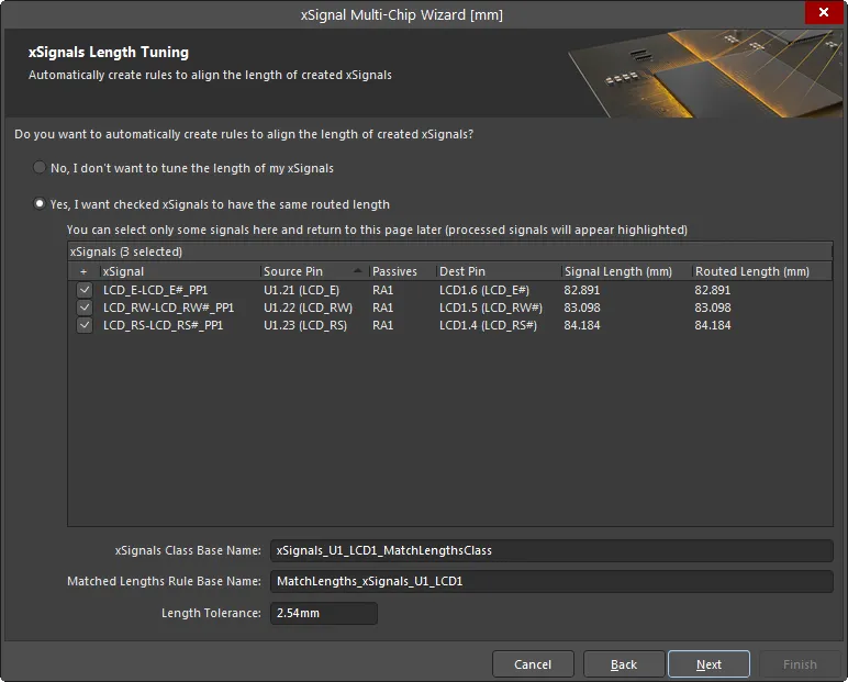
本页用于为已启用的 xSignals 自动创建一条“匹配长度(Matched Length)”设计规则。启用 only 你希望由这条新设计规则约束的 xSignals。如果你的设计需要多条具有不同要求的规则,在流程后续阶段,你将有机会为那些尚未定义规则的 xSignals 额外定义规则。此第一阶段也会呈现整体端到端 xSignals。在向导后续页面中,你将有机会为 xSignals 内部的各个分段定义设计规则——例如,从输出引脚到串联端接电阻的那一段。
如果你不想对 xSignals 进行长度调谐,请启用 No, I don't want to tune the length of my xSignals。启用该选项后,本页的其他选项将不可用。若要编辑并访问其他选项,请启用 Yes, I want checked xSignals to have the same routed length。
xSignals Class Base Name 字段用于为当前选定的 xSignals 定义名称。请输入一个有意义的名称,并考虑到你可能会对其他 xSignals 重复此流程。随后,这组 xSignals 将被一条设计规则所约束:规则名称来自你在 Matched Lengths Rule Base Name 字段中输入的内容,并采用指定的 Length Tolerance。
不确定哪些对象被作为目标?单击一个或多个条目以在 PCB 布局中高亮显示对应的信号路径。
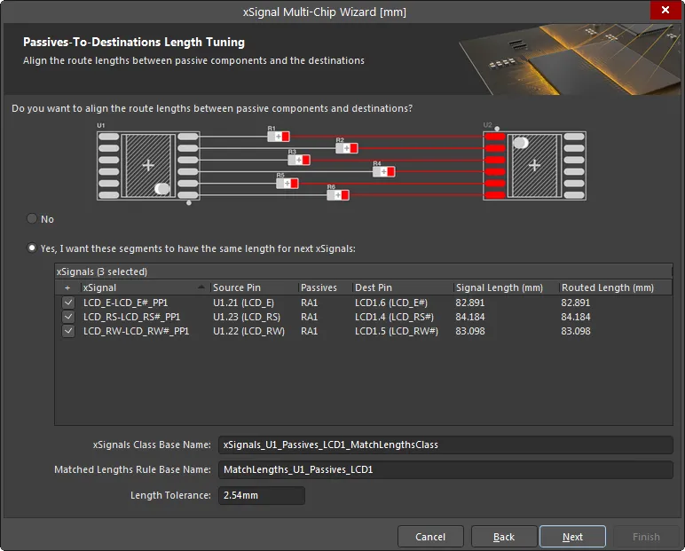
源端到无源器件长度调谐
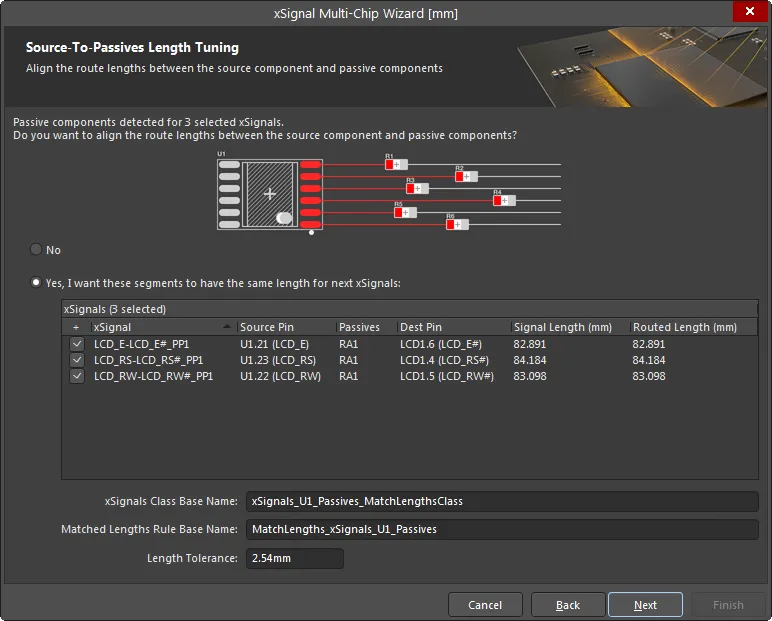
如果所选网络集合包含串联端接器件,向导将出现额外页面,让你有机会为这些网络分段创建额外的 xSignals 和设计规则。在上图中,你可以看到该向导页面用于为所选 xSignals(从源端引脚到端接器件)创建一条匹配长度设计规则。如果你需要为这些分段创建 xSignals / xSignal 类 / 设计规则,请启用 Yes, I want these segments to have the same length for next xSignals 选项,启用所需的 xSignals,并定义 xSignals Class Base Name、Matched Lengths Rule Base Name 和 Length Tolerance。将会创建额外的 xSignals 以配合这条匹配长度规则使用。
无源器件到目标端长度调谐
本页用于为所选 xSignals(从端接器件到目标端引脚)创建一条匹配长度设计规则。如有需要,请启用 Yes, I want these segments to have the same length for next xSignals 选项,启用所需的 xSignals,并定义 xSignals Class Base Name、Matched Lengths Rule Base Name 和 Length Tolerance。将会创建额外的 xSignals 以配合这条匹配长度规则使用。
报告并继续
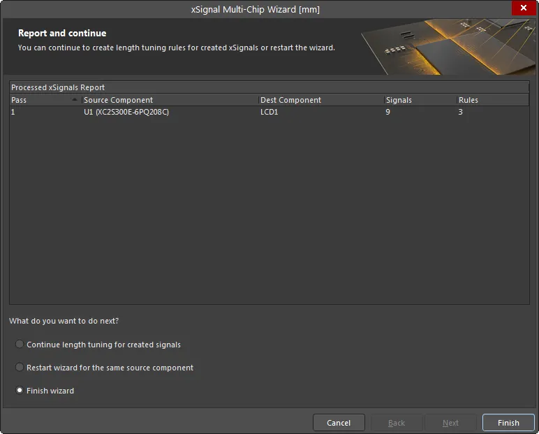
向导的此页面将详细列出即将创建的 xSignals 数量以及即将创建的设计规则数量。
在页面底部,你可以选择:
-
Continue length tuning for created signals – 如果你在前面页面禁用了某些 xSignals,而现在需要为这些 xSignals 继续完成定义额外规则的流程,则选择此项。
-
Restart wizard for the same source component – 如果你想丢弃这些设置,并在选择了相同器件/网络的情况下重新启动向导,则选择此项。
-
Finish wizard – 如果你已完成该源器件的 xSignal 与设计规则创建,则选择此项。
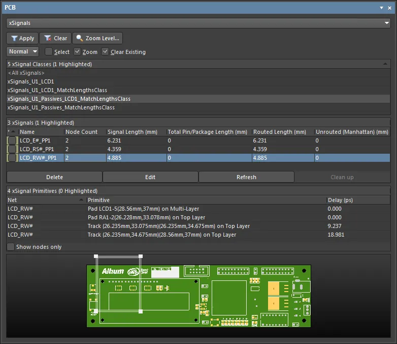
xSignals 会在 PCB 面板的 xSignal 模式中列出。在该面板中按下 Delete 键可移除所选的 xSignal 类或所选 xSignals。
这些 xSignals 已准备好进行长度调谐。要开始,请从主 Route 菜单或 Active Bar 中选择 Interactive Length Tuning 选项( )。
)。
你可以轻松移除长度调谐的手风琴(accordion)。在手风琴中的任意线段上单击一次以选中它,然后按 Delete。
请注意,当你放置手风琴时,现有走线段会在起点和终点处被打断。因此,如果你重复“调谐—删除”的过程多次,最终可能会得到一段看似笔直的布线,但实际上由许多短走线段组成。要将多个小走线段合并回单一线段,请从主菜单运行 Design » Netlist » Clean All Nets 命令。
On-Board DDR3 / DDR4
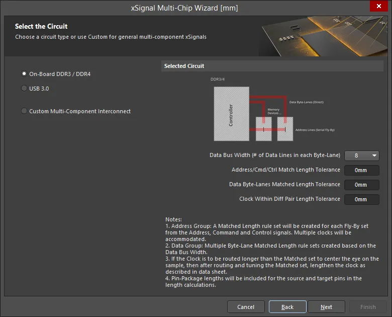
在此模式下,向导将为板载 DDR3/DDR4 自动创建 xSignals、xSignal Classes、Matched Length Groups、Diff Pair Matched Lengths 规则以及 Fly-By 拓扑。向导假设将使用 fly-by 布线拓扑。
选择源器件
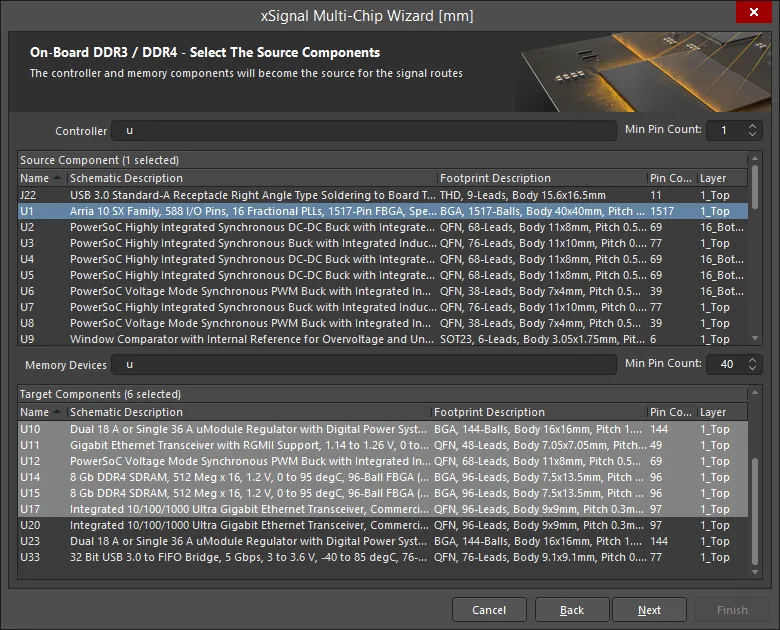
在此页面中,Wizard 会基于位号前缀和引脚数量识别所有潜在的源器件与目标器件。使用 Controller/Memory Devices 字段筛选器件/存储器件,并使用上下箭头按需设置 Min Pin Count,同时适用于 Source Component 和 Target Components 。然后选择一个源器件,并选择目标器件(可多选)。
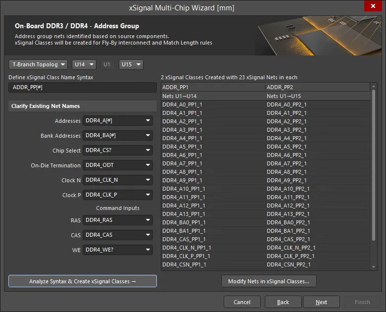
地址组
本页功能如下:
-
Fly-By Topology支持 T-Branch Topology 以及
选项。请从下拉列表中选择所需拓扑。
-
Fly-By Topology如果选择 Fly-By Topology,目标器件将按 fly-by 布线的点到点顺序列出。软件会尝试自动确定顺序。如果在器件放置之前运行向导,则需要使用下拉控件手动设置点到点顺序。
-
如果选择 T-Branch Topology(如上所示),一半目标器件会显示在源器件之前,另一半显示在源器件之后。使用下拉控件按需对目标器件排序。
-
Define xSignal Class Name Syntax:
-
起始默认值为
ADDR_PP[#]
-
[#] 表示存储器件的数量。
-
PP 后缀可按需更改。
-
向导会分析器件并在设计中查找这些后缀,然后使用下述方法显示完整的命名语法。如果这些不正确,请更新。
-
此处目标是自动找到与这些功能对应的网络。一旦找到网络,就会将命名语法填入这些字段。
-
随后会审查器件之间的网络:一旦找到后缀,就会识别前缀。例如,向导会查找
_A[#] 来定位地址线。
-
如果未找到后缀以“_”开头的网络,则只查找“_”之后的文本。也会检查其他分隔符,例如 “-” 或 “.”。
-
如果无法自动确定语法,你必须定义这些字段。使用下拉列表从板上现有网络中选择。
-
定义好顺序与命名语法后,单击 Analyze Syntax & Create xSignal Classes 按钮以构建 xSignals 列表。向导将根据语法以及器件连接方式生成 xSignal Classes,并显示在对话框右侧的网格中。Classes Created 的数量将与存储器件数量一致。
-
创建的类数量(例如 4)以及每个类中的 xSignal 网络数量(例如 26)。
-
xSignals 会按每个 xSignal 类分组显示为一列。将为每个类创建一条匹配长度设计规则。表格中的子标题表示这些 xSignals 的源器件与目标器件。
-
如果自动生成的列表不完整或不正确,请单击 Modify Nets in xSignal Classes 按钮以打开 Edit xSignal Class 对话框,并手动向类中添加或从类中删除网络。注意:如果随后再次单击 Analyze Syntax & Create xSignal Classes 按钮,手动更改将会丢失。
识别数据组网络
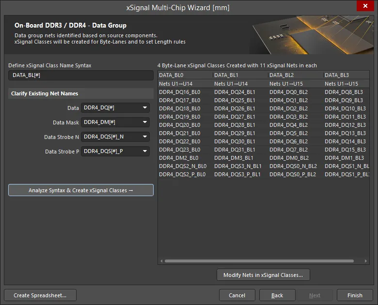
最后阶段是识别所有属于数据组(Data Group)的网络。
本页功能如下:
-
用户自定义 xSignal 类命名语法:
-
起始默认值为
DATA_BL[#]
-
[#] 表示 Byte-Lanes 的数量,它由数据线总数除以前面定义的数据总线宽度(Data Bus Width)确定。
-
BL 后缀可按需更改。
-
向导会分析器件并在设计中查找这些后缀,然后显示完整的命名语法。如果这些不正确,请使用下拉列表更新。
一旦定义好命名语法,点击
Analyze Syntax & Create xSignal Classes 按钮来生成 xSignals 列表。向导会根据该语法以及元件之间的连接方式,生成并在对话框右侧表格中显示 xSignal 类(xSignal Classes)。创建的类数量将与连接到存储器器件的字节通道(Byte-Lanes)数量一致。在表格区域上方,会显示已创建的类数量(例如 8)以及每个类中的 xSignal 网络数量(例如 11)。
将为这些 xSignal 类创建 Matched Length 长度匹配设计规则。表格中的子标题表示字节通道 xSignals 的源元件与目标元件。
如果自动生成的列表不完整或不正确,点击 Modify Nets in xSignal Classes 按钮打开 Edit xSignal Class 对话框,手动向某个类添加网络或从类中删除网络。注意:如果随后再次点击 Analyze Syntax & Create xSignal Classes 按钮,手动更改将会丢失。
点击 Create Spreadsheet 按钮,生成由向导创建的 xSignals 的 XLS 格式电子表格。
xSignals 和 xSignal Classes 已创建
向导会自动为以下内容创建 xSignals 和 xSignal Classes:
-
在 Address Group 页面中详细说明的地址 xSignals。
-
在 Data Group 页面中详细说明的数据 xSignals。
USB 3.0
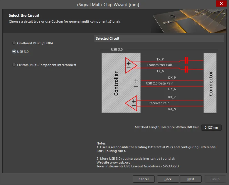
向导可以处理用户指定的每一组“控制器到连接器”配对之间的所有 USB 3.0 通道。向导会自动评估连接到控制器的差分对网络(Differential Pair nets),检测哪些网络一直延伸到连接器。该跨越路径可以包含无源器件以及多个网络。向导会用一个 xSignal 类来标识每一对差分对,并将该对中的每一条“腿”(leg)标识为一个控制器到连接器的 xSignal。
当你选择 USB 3.0 后,本页将包含一个用于 Matched Length Tolerance Within Diff Pair 的设置。请输入合适的值。该值用于向导创建的设计规则,并且可随时在 PCB Rules and Constraints Editor 中更改。此类用户自定义设置会被保存以供将来使用。
对于 USB 3.0,每个 USB 用户端口称为一个 channel。如图所示,每个通道包含三组差分对:发送(Transmit)、接收(Receive)和数据(Data)。
对于 USB 3.0,关键的布线设计要求是在每一对内部进行走线长度匹配;对与对之间的长度匹配并不那么关键。基于这一要求,并且由于 Matched Length 设计规则需要差分对来检查一对网络内部的长度,向导会检查是否已定义 Differential Pair,并在未定义时自动创建合适的差分对。随后向导创建的 Matched Length 设计规则会被配置为检查长度匹配 Within Differential Pair Length。注意:该规则被配置为比较整体 xSignal 内部“成对网络”的两条腿长度;它不会比较每个差分对内部的两条腿长度。
选择源元件与目标元件
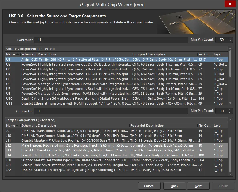
在此页面中,向导会基于位号前缀(designator prefix)和引脚数量识别所有潜在的源元件与目标连接器。
-
按需设置 Controller 位号、Connector 位号以及 Min Pin Count 的过滤前缀。
-
选择一个源元件。
-
选择目标元件(可多个)。
如果你选择了多个目标元件,应在向导下一页使用下拉列表分别检查这些元件的 xSignal 与网络命名语法是否正确且完整。
通道定义差分对分组
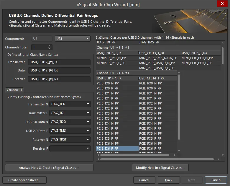
在此页面中,定义一套命名语法,使向导能够识别相关的发送、接收与数据差分对网络,并将其纳入 xSignals。随后,每一对 xSignals 会被聚类为一个 xSignal 类,这些类用于限定 Matched Length 设计规则的作用范围。
本页功能如下:
-
控制器的位号会显示在 Components 标签旁。其旁边的下拉列表包含在向导上一页中选择的所有 Connectors。
-
所显示的命名语法选项适用于下拉列表中列出的每个连接器。请依次选择每个连接器,并检查所选命名语法是否完整且适用。
-
如前所述,对于 USB 3.0,每个 USB 用户端口称为一个 channel。你可以将通道数量(Channels Total)设置为 1 到 32。通常,每个连接器只有一个通道。
-
在每个 USB 3.0 通道内,有三条差分对路径:发送、接收和数据,它们从控制器连接到连接器。向导会为每个正端网络创建一个 xSignal(按需跨越串联器件),并为每个负端网络创建另一个 xSignal,然后创建一个 xSignal 类来表示该“控制器到连接器”的配对。Define xSignal Class Name Syntax 组用于指定这些 xSignal 类的名称。如果尚未定义,向导也会创建合适的 Differential Pairs。
-
Define xSignal Class Name Syntax – 创建的 xSignal 类将按指定方式命名,每个通道会用一个数字值替换
[#]。请按需输入你偏好的字符串。
-
Channel <N> – 这些字段定义用于识别相关发送/接收/数据网络名称的掩码(mask)。
-
向导内置了大量预定义命名方案模板,会进行检查并通常会自动填充这些字段。如果未自动填充,请从下拉列表中选择正确名称,或输入合适的网络命名语法。
-
配置好命名字段后,点击 Analyze Nets & Create xSignal Classes 按钮。
-
向导将为所有通道创建 xSignals、xSignal Classes 以及 Matched Length 规则。注意:每次重新运行向导都会再次创建这些内容。如果你计划再次运行向导,请先删除它们。
-
生成的 xSignal 类名称及其成员 xSignals 会在网格中详细列出。
-
点击 Create Spreadsheet 按钮,生成由向导创建的 xSignals 的 XLS 格式电子表格。
-
点击 Finish 完成向导。
在元件之间创建 xSignals 对话框
如果需要定义大量 xSignals,使用 Create xSignals Between Components 对话框会更高效。该对话框可通过 Design » xSignals » Create xSignals 命令访问,提供源元件与目标元件,并允许你在一次操作中创建一个或多个 xSignals。

使用该对话框可以快速识别并创建多个 xSignals,并将它们添加到所需的 xSignal 类中。
操作方法为:
-
选择一个 Source Component。
-
选择一个或多个所需的 Destination Components。
-
选择感兴趣的 Source Net(s)。当前连接到所选源元件的所有网络都会被列出。对于与特定类相关的网络,可从 Net Class 下拉列表中选择该类。
-
点击 Analyze 按钮。软件会尝试识别在所选网络条件下、位于所选源元件与目标元件之间的潜在 xSignals。所有包含所选网络并在所选源/目标元件之间延伸的可能 xSignals,都会列在 xSignals 字段中。注意:分析算法会沿着所选网络的当前拓扑结构进行追踪,这会影响所建议的 xSignals。
如有需要,软件也可以通过在 Analyze 下拉列表中选择相应选项来穿越串联器件:Search for direct connections、Through 1 series component、Through 2 series components 或 Multipath coupled nets。
-
分析完成后,潜在 xSignals 会列在对话框下方区域,并默认全部启用以供创建。请仔细检查建议的 xSignals 列表,仅启用需要的项。可使用右键上下文菜单中的命令来切换多条条目的启用状态。
-
在对话框底部选择所需的 class,或输入名称以创建新类。如果未选择任何类,xSignals 仍会被创建,你可以在 Object Class Explorer 对话框(Design » Classes)中将它们添加到任意 xSignal 类。使用类可以大幅简化设计规则的创建与配置。
-
点击 OK 创建 xSignals。
对话框将关闭,你将返回到设计空间。新的 xSignals 会在 PCB 面板的 xSignals 模式中列出。
使用每个列表上方的过滤器可快速定位感兴趣的元件或网络;支持通配符。
从已连接网络创建 xSignals 对话框
如果你要创建包含串联端接器件的 xSignals,一个好的方法是使用 Create xSignals from connected nets 命令。只要选中了某个元件,就可以通过主菜单中的 Design » xSignals 子菜单或右键 xSignals 子菜单使用该命令。
该命令用于从选定的串联端接器件(例如电阻或电容)向外构建 xSignals。它既支持一个或多个分立器件,也支持一个或多个多实例的封装式器件,例如电阻网络。运行该命令后,将打开 Create xSignals From Connected Nets 对话框。

使用该对话框创建跨越所选串联器件的 xSignals。在此示例中,提出了两个可能的 xSignals,但只会创建其中一个。
操作方法为:
- 选择单个 Source Component。
-
选择感兴趣的 Source Net(s)。当前连接到所选源器件的所有网络都会被列出。对于与特定类相关联的网络,请从 Net Class 下拉列表中选择该类。
-
单击 Analyze 按钮。软件会尝试识别针对所选源器件及其所选网络可能存在的 xSignals。所有可能的 xSignals 都会列在 xSignals 字段中。
-
分析完成后,潜在的 xSignals 将列在对话框的下方区域,并且全部默认启用以便创建。请仔细检查建议的 xSignals 列表,仅启用所需的项。可使用右键上下文菜单中的命令来切换多条条目的启用状态。
-
在对话框底部选择所需的 class,或输入名称以创建新类。如果未选择任何类,xSignals 仍会被创建,你可以在 Object Class Explorer 对话框(Design » Classes)中将它们添加到任意 xSignal 类中。使用类可以极大简化设计规则的创建与配置。
-
单击 OK 以创建 xSignals。
对话框将关闭,你将返回到设计空间。新的 xSignals 将在 xSignals 面板的 PCB 模式中列出。
使用每个列表上方的筛选器可快速定位感兴趣的器件或网络;支持通配符。
网络拓扑的作用
当你定义一个 xSignal 时,它位于两个节点或焊盘之间。然而,当你在 xSignals 面板的 PCB 模式中选择该 xSignal 时,它实际上会沿着这两个焊盘之间的连接线路径显示,表明这是软件假定该 xSignal 将要布线的路径。之所以这样做,是因为它遵循了为该网络定义的拓扑。网络拓扑由适用的 Routing Topology 设计规则定义;默认拓扑为 Shortest。
这个简单的动画展示了一个 CPU 连接到四颗 DDR3 内存芯片,并将采用飞线式(fly-by)布线策略。DRAM_A2 xSignal 类包含四条 xSignals。首先选择该类,然后依次选择每条 xSignal。你可以看到 xSignal 路径如何遵循网络的拓扑,而当前拓扑设置为默认值——Shortest。

由于网络拓扑当前设置为 Shortest,xSignals 并未遵循从处理器到内存芯片所需的路径。
如果你计划使用 Create xSignals Between Components 对话框,则需要配置网络的拓扑(一个或多个),以确保 xSignal 分析算法能够理解所要布线的 xSignal 的预期路径。
xSignal 创建命令
除了 Design » xSignals » Create xSignals 命令外,在满足特定条件时,xSignals 子菜单中还提供其他 xSignal 创建命令。
下面汇总了这些命令及其可用条件:
| 命令 |
说明 |
| Create xSignal from selected pins |
立即创建单条 xSignal。当在设计空间中选择了两个或更多焊盘时可用,并且与在所选焊盘之一上右键时出现的命令相同。
|
| Create xSignals between components |
当在设计空间中选择了器件时可用。运行后会打开 Create xSignals Between Components 对话框,并预先选中这些器件。请确保已选择正确的 Source 和 Designation 器件,然后完成分析/创建流程。
启动该命令后,将打开 Create xSignals Between Components dialog。使用该对话框按如下方式创建 xSignals:
-
所选源器件将显示为在 Source Component 区域中已选中。
-
工作区中选中的其他器件将显示为在 Destination Components 区域中已选中。如未选中,请现在进行选择。
-
默认情况下,将选中与源器件焊盘相关联的所有网络(在 Source Component Nets 区域中)。请按需调整该选择。
-
单击 Analyze 按钮——软件会尝试针对所选网络,识别在所选源器件与目标器件之间可能存在的 xSignals。
请注意,分析算法会遵循所选网络的当前拓扑。
如有需要,软件也可以通过选择该按钮关联下拉菜单中的相应模式来穿过串联器件进行搜索。可用模式为:Search for direct connections、Through 1 series component、Through 2 series components 和 Multipath coupled nets。
-
所有识别到的 xSignals 都会列在对话框的 xSignals 区域中。默认情况下全部勾选以创建——请按需调整。
-
你也可以选择将创建的 xSignals 关联到某个 xSignal 类。可以选择现有 xSignal 类,或输入新类名称。也可以留空;之后仍可将这些 xSignals 添加为所需类的成员。
-
单击 OK 以创建 xSignals。对话框将关闭,你将返回到设计空间,并显示一个筛选视图以展示新创建的 xSignals。如果指定了 xSignal 类,则会创建该类(若尚不存在)并将 xSignals 关联到其中。
|
| Create xSignals from connected nets |
当存在一个或多个串联端接器件需要为其创建 xSignals 时使用此命令。选择端接器件,然后运行该命令以打开 Create xSignals from Connected Nets 对话框,准备完成创建一组 xSignals 的流程。使用该对话框按如下方式创建 xSignals:
-
所选源器件将显示为在 Source Component 区域中已选中。
-
默认情况下,将选中与源器件焊盘相关联的所有网络(在 Source Component Nets 区域中)。请按需调整该选择。
-
单击 Analyze 按钮——软件会尝试识别从所选器件发出的、针对所选网络可能存在的 xSignals。
请注意,分析算法会遵循所选网络的当前拓扑。
-
所有识别到的 xSignals 都会列在对话框的 xSignals 区域中。默认情况下全部勾选以创建——请按需调整。
-
你也可以选择将创建的 xSignals 关联到某个 xSignal 类。可以选择现有 xSignal 类,或输入新类名称。也可以留空;之后仍可将这些 xSignals 添加为所需类的成员。
-
单击 OK 以创建 xSignals。对话框将关闭,你将返回到设计空间,并显示一个筛选视图以展示新创建的 xSignals。如果指定了 xSignal 类,则会创建该类(若尚不存在)并将 xSignals 关联到其中。
|
| Create xSignals |
打开 Create xSignals Between Components 对话框。此命令始终可用。使用该对话框按如下方式创建 xSignals:
-
在 Source Component 区域中选择一个源器件。
-
在 Destination Components 区域中选择一个或多个目标器件。
-
与源器件焊盘相关联的所有网络将列在 Source Component Nets 区域中。选择感兴趣的网络。
-
单击 Analyze 按钮——软件会尝试针对所选网络,识别在所选源器件与目标器件之间可能存在的 xSignals。
请注意,分析算法会遵循所选网络的当前拓扑。
如有需要,软件也可以通过选择该按钮关联下拉菜单中的相应模式来穿过串联器件进行搜索。可用模式为:Search for direct connections、Through 1 series component、Through 2 series components 和 Multipath coupled nets。
-
所有识别到的 xSignals 都会列在对话框的 xSignals 区域中。默认情况下全部勾选以创建——请按需调整。
-
你也可以选择将创建的 xSignals 关联到某个 xSignal 类。可以选择现有 xSignal 类,或输入新类名称。也可以留空;之后仍可将这些 xSignals 添加为所需类的成员。
-
单击 OK 以创建 xSignals。对话框将关闭,你将返回到设计空间,并显示一个筛选视图以展示新创建的 xSignals。如果指定了 xSignal 类,则会创建该类(若尚不存在)并将 xSignals 关联到其中。
|
在平衡 T 形模式中定义分支点
平衡 T 形布线策略的挑战之一,是如何使主干(trunk)以及 T 点之后各分支(branch)的长度实现均衡。网络中可用的节点仅位于焊盘处,因此无法为主干单独定义 xSignals,也无法为从分支点到每个分支末端分别定义 xSignals。分支点在下图中以红点标示。
解决此问题的一种方法是在该网络中添加一个单引脚器件。创建一个只有单个焊盘的器件,其焊盘尺寸与设计中使用的过孔尺寸一致。如果分支点器件的焊盘是单层的,那么还可以将其与盲孔或埋孔配合使用:把它放置在过孔的起始层或结束层上,从而在布线创建方式上获得完全的灵活性。如果你只想在 PCB 上包含该分支点器件,请将分支点器件的 Type 设置为 Mechanical,以将其从 BOM 中排除,并防止与原理图发生任何同步问题。如果你计划在原理图中也包含该分支点器件,则可以将器件的 Type 设置为 Standard (no BOM)。

平衡 T 形布线可能需要在中间分支点之间进行长度匹配。
由于分支点是网络中的一个节点,你现在可以仅为主干、为每条主要分支以及(如有需要)为每条次要分支定义 xSignals。然后即可用它们来限定长度匹配设计规则的作用范围,使设计人员能够完全控制长度匹配需要细化到什么程度。

 AI 翻译
AI 翻译