A new room can also be created by defining a new constraint in the PCB Rule and Constraints Editor or the Constraint Manager.
Which approach is being used to Define the Design Constraints?
Altium Designer supports two distinct approaches to defining design constraints: the Constraint Manager and the PCB Rule and Constraints Editor.
The PCB Rule and Constraints Editor was the initial interface developed for defining constraints in the PCB editor. If the PCB Rule and Constraints Editor is used, the designer defines: what objects the constraint (rule) applies to, and, how those objects are to be constrained. This approach is powerful in that it allows the designer to precisely target the objects they want to constrain; it could apply to everything (for example all nets), or zoom right in to a specific object on the board (that pad). This flexible method of targeting the design objects is achieved using a rules engine driven by a query language.
The Constraint Manager brings an object-centric focus to the task of defining the constraints. The designer works from the perspective of the objects, applying the various electrical and physical constraints required for the design, in a spreadsheet-like interface, with the object(s) highlighting in the graphical editor as they are selected in the Constraint Manager. This allows the designer to easily configure and examine all of the requirements for an object, for example: this net class, is to be routed at this width, with this clearance, using this routing via, and this polygon connection style. You might also require that net class to be: routed on these layers, with these impedances. This object-centric view is not possible in the PCB Rule and Constraints Editor. Ultimately the software converts the object-centric constraints into the same format of rules that is defined in the PCB Rule and Constraints Editor, switch to the All Rules view when the constraints have been opened from the PCB editor to view them.
The Constraint Manager is only available in the PCB design project if the Constraint Management option was enabled in the Create Project dialog during project creation (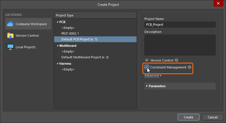 ). If it was not, then the PCB Rule and Constraints Editor must be used. To quickly check which approach to design constraint management is used in the current PCB project, open the project's PCB document, click the Design menu, and check which command is available: Constraint Manager – the Constraint Manager is used for this project, or Rules – the PCB Rule and Constraints Editor dialog is used for this project.
This documentation page shows images of the constraints as they are defined in both the PCB Rule and Constraints Editor dialog and the Constraint Manager. Note that the terms constraint and rule are used interchangeably.
Adding a New Room Definition Design Constraint
In the PCB Rules and Constraints Editor
For each room that is placed or created, an associated Room Definition design constraint is automatically created. The converse is true too, if you add a new rule of this type, the corresponding room object will appear in the design space. Note that the opposite also applies, if you delete a room in the graphical editor the constraint is automatically deleted, or, if you delete the design constraint then the graphical object is deleted.
If the room constraint is being defined from the PCB Rules and Constraint Editor, then a default 5-inch by 5-inch room object is created, 1 inch from the Absolute Origin (the bottom left of the editing space). Note that the origin marker displays the user-defined Relative Origin, which can be set anywhere in the editing space.
 When a new room constraint is added, a default room is defined in the editing space.
Once the constraint has been added you can return to the editing space and graphically edit the room. Alternatively, when you are in the PCB Rules and Constraints Editor you can edit the room constraint, then click the Define button to interactively define the shape. Since a room defines an area on the board, it is more common to interactively place the room and have the design constraint automatically created.
Learn more about how to add a new constraint in the PCB Rules and Constraints Editor.
In the Constraint Manager
To create a new confinement (room) constraint in the Constraint Manager: switch to the All Rules view, select Room Definition in the Placement category, then right-click in the Advanced Rules list and select Add Advanced Rule from the context menu, as shown below.
 A new room constraint can be added in the Constraint Manager.
At this stage the room object does not exist in the graphical editing space, you must now click the Define button (switching you to the PCB editor) and define the shape of the room. Once this has been done, both the room constraint and the room object exist, and the constraints can be saved.
-
If the room constraint is going to be used to constrain objects to be inside (or outside) that area of the board, the next step is to configure the Object Match and other constraint settings at the bottom of the Constraint Manager. Read on to learn more about that.
-
If the room constraint is going to be used as an area definition in another type of constraint, such as the routing width, refer to the Defining Constraints Within a Room section to learn more.
Learn more about how to add a new constraint in the Constraints Manager.
What is a Room Constraint?
As stated earlier, a room is a defined area on one of the PCB surface layers, that is used to define design requirements within that area of the board.
All design constraints have two key elements:
-
what objects this constraint applies to (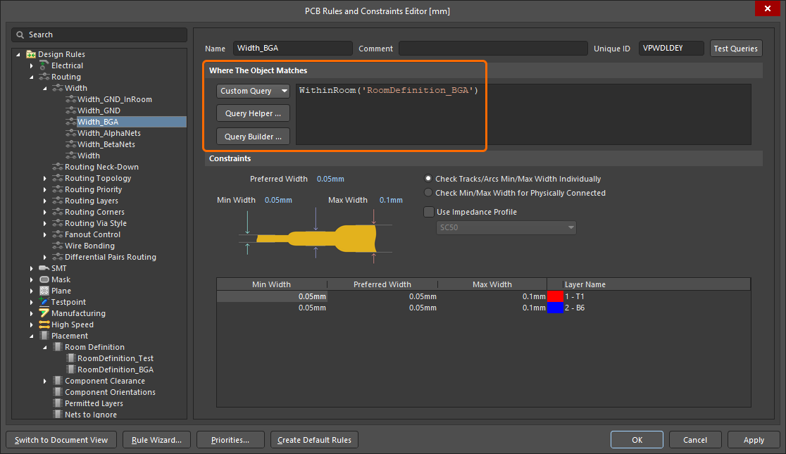 ), and,
-
how those objects are to be constrained (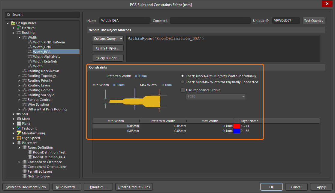 ).
).
If the room constraint is defined in an area of the board where there are no components, the Object Match criteria (the objects this constraint applies to) defaults to False, meaning this constraint applies to no objects. Edit this as required.
 The newly created room definition. Note that the rule scope is False, meaning it applies to no objects.
Constraining a Class of Components
A common way to use a room constraint is to define the location of a component class, locking that class of components to a specific area of the board.
 The Encoder class of components is constrained within the room called Room-Encoder, on the Top Layer of the board.
The image above shows how the Encoder class of components is constrained within the Room-Encoder room, on the Top side of the board in the PCB Rules and Constraints Editor (essentially the same as in the Constraint Manager 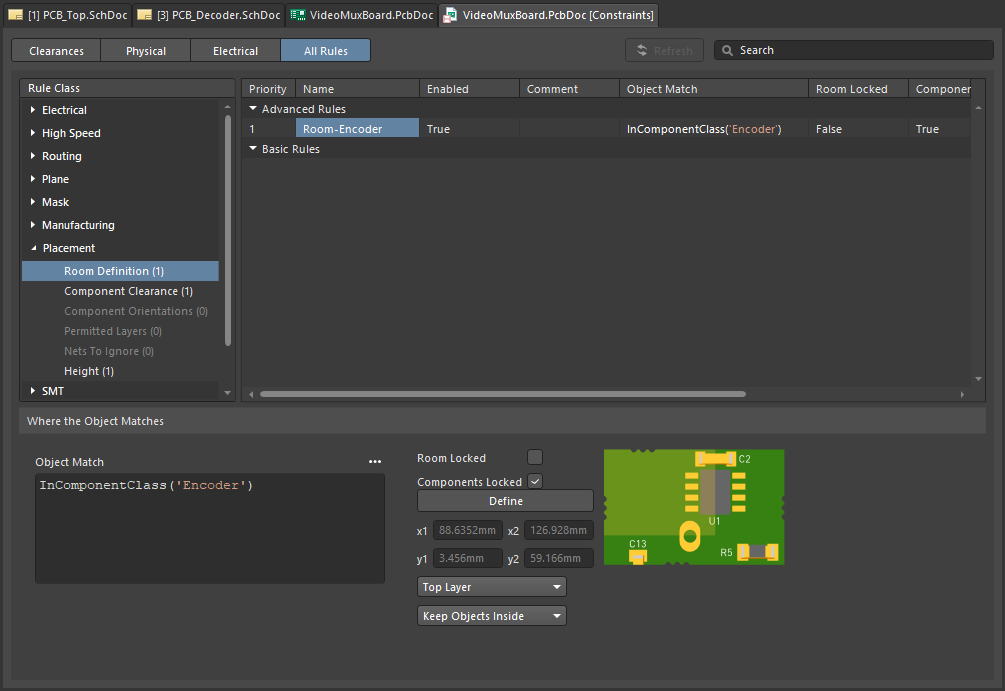 ). Once component(s) have been assigned to a room, they move when the room is moved. To move a room without moving the components, temporarily disable the associated Room Definition rule.
Learn more about the Room Definition design constraint.
The PCB editor includes a number of powerful tools for working with rooms, read more in the Working with Rooms section of this page.
As well as being a design constraint in its own right (Room Definition), a room can also be used as an object to focus the scope of another design constraint to an area of the board, such as Width, Clearance or Via Style. This topic is discussed in the the Defining Constraints Within a Room section of this page.
Rooms can also be used in a design that includes repeated sections of circuitry – known in Altium Designer as a multi-channel design. In a multi-channel design the engineer captures the schematic for the repeated channel once, and adds information on how many times the channel is repeated. When the design is transferred from schematic to PCB, the software automatically stamps that repeated circuitry out the required number of times, placing each channel in its own design room. Once the PCB designer has placed and routed one of those channels within its room, they can then instruct the software to replicate that placement and routing across all of the other channels.
Learn more about multi-channel design.
