Constraints EditorとConstraint Managerのどちらを持っていますか?
PCBプロジェクトが作成されたときにプロジェクト作成ダイアログでConstraint Managementオプションが有効にされていた場合、そのプロジェクトの設計制約を定義するために Constraint Managerが使用されます。この場合、PCBルールとConstraints Editorダイアログ、そしてこのページで説明されているConstraints Editorは、PCBエディターで利用できなくなります。それ以外の場合は、以前のアプローチ(設計指示とPCB Rule and Constraints Editorダイアログ / Constraints Editor)のみが使用できます。
現在のPCBプロジェクトでどのアプローチが設計制約の定義に使用されているかをすぐに確認するには、プロジェクトのPCBドキュメントを開き、Designメインメニューをクリックし、どのコマンドが利用可能かを確認してください:
-
Constraint Manager – このプロジェクトにはConstraint Managerが使用されています。
-
ルール – このプロジェクトにはPCB Rule and Constraints Editorダイアログが使用されています。このダイアログから、このページで説明されているConstraints Editorに切り替えることができます。
Constraints Editorは、ドキュメントベースのユーザーインターフェースであり、PCBレイアウトに使用される設計制約ルールを表示、作成、管理するための代替アプローチを提供します。エディタは、優先順位が高い順に6つの選択可能なルールセクション - ネット、差動ペア、xSignals、ポリゴン、コンポーネント、Advanced - に整理されています。この配置では、最初の5つのセクション(ネットからコンポーネントまで)はルールの設計オブジェクトビューを表し、Advancedビューセクションはより複雑なルール(通常はクエリを使用)に適用され、これらは単純な設計オブジェクト指向のルールとして表現できないものです。

Constraints Editor – デザインルールを管理するための別のアプローチ。
Constraints Editorは、PCBルールおよびConstraints EditorダイアログでSwitch to Document Viewボタンをクリックすることでアクセスします。
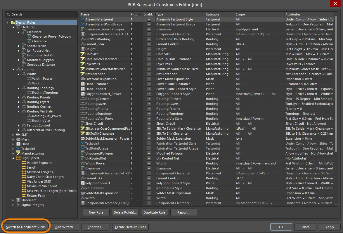
「PCBルールとConstraints Editor」ダイアログからConstraints Editorビューに切り替える。
エディタ
のPropertiesパネルで
Switch to Dialog Viewボタンをクリックして、
PCBルールとConstraints Editorダイアログに戻ります。
 Constraints EditorビューからPCB Rules and Constraints Editorダイアログに戻る。
または、メインメニューから
Tools » Switch to Dialog Viewコマンドを使用してください。
Switch to Dialog Viewボタンやコマンドが利用できないですか?
Constraints Editorではなく
Constraint Managerを使用しているか確認してください –
詳細を見る。
エディターを使用する利点のいくつかは以下の通りです:
-
ダイアログではなくドキュメントベースのプレゼンテーションインターフェースを使用することで、PCBエディターおよび関連機能がアクティブでアクセス可能な状態を維持します。
-
クエリベースのルールスコーピングから適用されるオブジェクトタイプマッチングへの移行により、制約ルールの作成が簡素化されます。
-
ルールの優先順位は、設計オブジェクトの自然な階層に基づいて自動的に設定されます。
-
一般的な構文、割り当て、スコーピングのエラーを検出するためのインタラクティブなルール検証チェック。
制約ルールのタイプ
Constraints Editorでは、マッチングスコープにより複雑なクエリ式を特徴とする既存のルールは高度なルール(またはカスタムルール)と見なされ、より単純なルールはオブジェクトタイプに基づいた基本ルール、つまりチェックされる設計オブジェクトのタイプに基づいたルールとして再表現されます。
高度な(クエリベースの)形式のほとんどのルールは、ルールをBasic Rulesリストにドラッグアンドドロップするか、高度なルールの右クリックメニューからMove Custom Rule to Basicオプションを選択するか、メインメニューからTools » Convert » Migrate Advanced Rules to Basicコマンドを使用することで、よりシンプルな基本ルールに変換できます。このコマンドを起動すると、Migration of Advanced Rules to Basicダイアログが表示され、移行可能な基本ルールの数についての情報を提供した後、移行を確認するよう求められます。変換されると、高度なルールのクエリベースの範囲は、基本ルールのオブジェクトタイプの資格に解釈されます。

クエリベースの高度なルールを、よりシンプルな基本ルールに変換できます。
ルールの優先順位
一般的に、ルールの優先順位はシステムによって自動的に扱われます。これは、インターフェース内のルールビューボタンの配置によって示されており、ルールの優先順位に従って左から右へと配置されています - ネットが最低の優先順位を持っています。
-
高度な(またはカスタム作成された)ルールは、基本オブジェクトルールの順序に優先し、高度なビュー内でエントリを上下にドラッグすることによって手動で並べ替えることができます。
-
逆に、基本ルールはシステムによって自動的に優先され、ドキュメントインターフェースのオブジェクトセクション(ネットからコンポーネントまで)に示されている設計オブジェクトタイプに基づいています。
-
(基本の)オブジェクトルールセクション内では、優先順位は全て(最低)からオブジェクトクラス、オブジェクト(最高)の順に並べられ、推測により、全ての範囲を持つルールが基本ルールに変換された場合、最低の優先順位を持つことになります。
-
基本ルールに明示的な優先順位を設定するには、ルールを右クリックし、Move Basic Rule to Advancedオプションを選択するか(またはメインメニューからTools » Convert » Migrate Basic Rules to Advancedコマンドを使用します)。コマンドを起動した後、基本ルールを高度なルールに移行ダイアログが表示され、移行可能な基本ルールの数についての情報を提供した後、移行を確認するよう求められます。手動でその優先順位を高度なビューで設定します。これは、全ての範囲を持つルール以外に適用されます。例えば、ネットビューでは、ネットクラスまたはネットの範囲が指定されたルールを高度なルールに変換(移動)できます。
新しいカスタム制約ルール
エディターのデフォルトのAdvancedモードで新しいルールを作成することは( ボタンを使用して指示、選択)、PCBルールとConstraints Editorダイアログでルールを構築することに似ています。右クリックのコンテキストメニューからAdd Custom Ruleを選択するか(または
 ボタンやメインメニューからのEdit » Add Constraintコマンドを使用)、必要に応じてクエリベースのマッチングスコープを追加します(
 )、その後、列グリッドまたは下部のグラフィカル表現で制約パラメータを入力します。
独自のカスタム制約ルールを作成する
高度なカスタムタイプルールの作成プロセスを繰り返し簡素化するために、Constraints Editor はクエリベースのオブジェクトマッチングスコープをScopes Libraryダイアログに保存できます(Object Match列でをクリックしてExport to Libraryを選択するか、PropertiesパネルのAdvanced constraints optionsモードでScopes Library領域のEdit Libraryボタンをクリックすることでアクセスできます)。ライブラリはPropertiesパネルで提示され、カスタムスコープをインポート、管理、再利用のために他のカスタム制約ルールにエクスポートできます。ルール内のライブラリベースのスコープの使用は、ルールのObject Match列エントリーにアイコンで示されます。
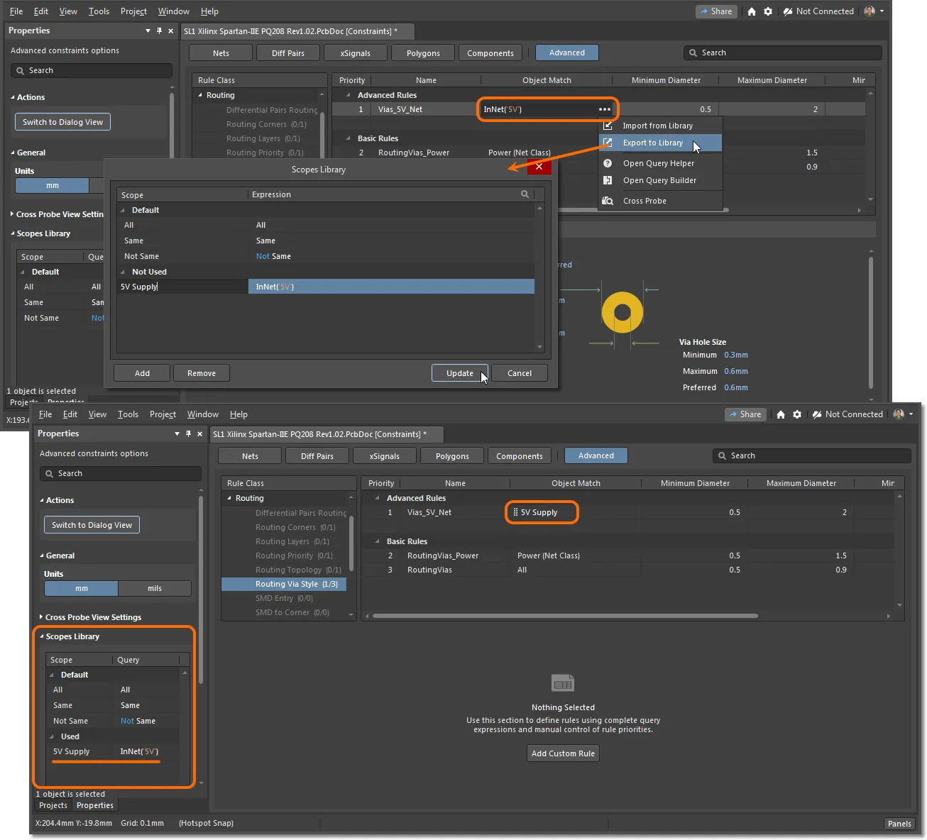
カスタムルールの作成を簡単にするためにスコープライブラリを使用します。
-
ライブラリベースのスコープがルールに適用された後、オブジェクトマッチ(スコープ)フィールドのメニューを使用して、スコープエントリを削除(スコープをクリア)するか、スコープをクエリベースの形式に戻す(スコープをデタッチ)ことができます。
-
スコープライブラリ自体をカスタムスコープXMLファイルとしてエクスポートできることにも注意してください。これを使用して、別のAltium Designerインストールのスコープライブラリを選択することができます。
-
リスト内の異なる位置にルールをドラッグアンドドロップして、その優先順位を変更します。カスタムルールは最高優先順位を採用します。基本(オブジェクト)ルールエントリの優先順位は、その固有の階層によって自動的に決定されることに注意してください。
-
現在選択されているルールを削除するには、右クリックしてルールを削除を選択するか、メインメニューからEdit » Remove Constraintを選択します。
-
制約ドキュメントファイルをPCBプロジェクトに保存するには、File » Save to PCB(ショートカット:Ctrl+S)を選択します。
-
設計ルールは、Constraints Editorからエクスポートおよびインポートすることができます。これにより、異なるデザイン間でお気に入りのルール定義をロードすることができます。File » Export To File コマンドを使用して、PCBルールファイル(*.rul)を保存します。File » Import From Fileコマンドを使用して、既存の*.rul PCBルールファイルをロードします。どちらの場合も、設計ルールタイプを選択ダイアログが開き、エクスポート/インポートする設計ルールを選択できます。
このページで説明されている
Constraints Editorではルールのインポート/エクスポートがサポートされていますが、設計制約を管理するための別のインターフェースである
制約マネージャでは現在サポートされていないことに注意してください。現在のPCB設計プロジェクトで利用可能なアプローチを確認してください –
詳細を学ぶ。
デザインオブジェクト制約モード
制約ルール作成において、よりシンプルなデザインオブジェクト指向アプローチを取るために、ルールグリッドの上部にある適切なオブジェクトモードボタンを選択して、デフォルトのアドバンスドモードから変更します。概念的に、これらのモードは、破壊可能なデザインルールの作成よりも、デザインオブジェクトがどのように適用されるかを制限(限定)することに焦点を当てた、より統合されたルールインターフェースを提示します。デザインオブジェクトボタンの位置序列は、基本的なネット(およびクラス)から統合されたコンポーネント、さらにアドバンスドモードまで、オブジェクトの複雑さ(およびルールの優先度)が増すことを関連付けています。
アドバンスドモード () では、基本的な Via や Width 制約ルールのように、ルールがタイプ別にグループ化されています。さらに具体的なルールを追加したり、クエリ言語要素を含めることで、ルールの特定性を高めることができます。
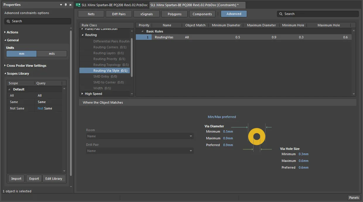
高度なモードのConstraints Editorでは、ルールがタイプ別にグループ化されます。
逆に、オブジェクト指向のビュー(ネットからコンポーネントへ)は、設計オブジェクト(例:ネット)やクラス(例:ネットクラス)によってルールを整理し、その結果、ルールが設計にどのように適用されるかの直接的な概要を提供します。オブジェクトタイプに適用されるルールの概要を見るには、左列でオブジェクトまたはクラスを選択して関連するすべてのルールを表示するか、All を選択してオブジェクトタイプに関連するすべてのルールを表示します。以下の例は、ネットに関連するルールの概要を示しています( )。
)。

Constraints Editorのオブジェクト指向ビューでは、ルールが設計オブジェクトごとにグループ化されます。
例えば、下記のようにネットオブジェクトタイプを選択した場合、デザインオブジェクト指向アプローチを使用すると、基本的なビアと幅のルールが一つの複合エントリに統合されます。グリッドレイアウトは、(ネット)オブジェクトやクラスごとにさらに制約を追加するための準備も提供しています。
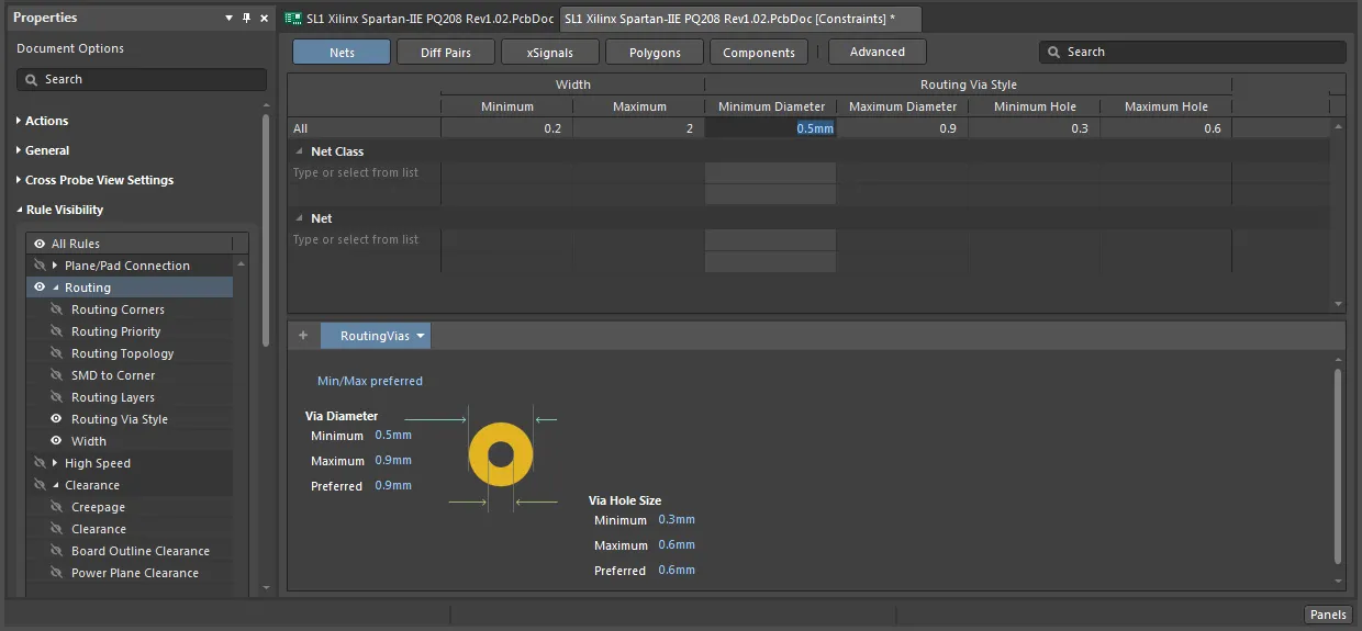
選択されたオブジェクトタイプの制約を表示するオブジェクト指向ビュー。
さらに、この例でより具体的な制約を追加するには、ネットまたはネットクラスが選択され、望ましいタイプの制約ルールに対応するグリッドセルに適切な値が入力されるだけでよいです。下に示すように、Powerネット(そのクラスによって定義される)にはより大きなViaサイズが許可され、5V供給レールネットには増加した最大トラック幅が割り当てられています。実際には、4つのルールが1つのシンプルなグリッドビューに含まれています。つまり、5Vネットの幅制約、他のすべてのネット幅の制約、PowerネットのViaサイズ制約、および他のすべてのネットクラスのViaサイズ制約です。

異なるオブジェクトとそのグループ(例えば、ネットとネットクラス)に対して、より具体的な制約を追加します。
以下の例に示すように、現在選択されている制約ルールのバリエーションを追加するには、 ボタンを使用します。例えば、追加の
 5V ネットルールが Bottom 層の好ましい幅を設定します。 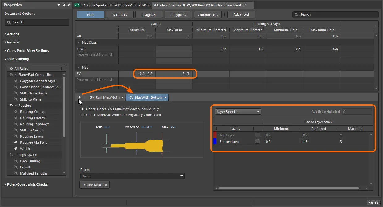
選択した制約のバリエーションを追加できます。
グリッドエントリ内のルールタイプの有効性は、利用可能な列によって設定され、これは順番に、PropertiesパネルのRule Visibilityリストで有効にされたものによって指定されます。例えば、Rule VisibilityリストでClearanceエントリを有効にすると、下に示すように、NetsオブジェクトタイプにClearance列が追加されます。適用可能なクリアランスルールを追加するには、ネットまたはクラスのスコープと適切な距離パラメータを入力するだけです。
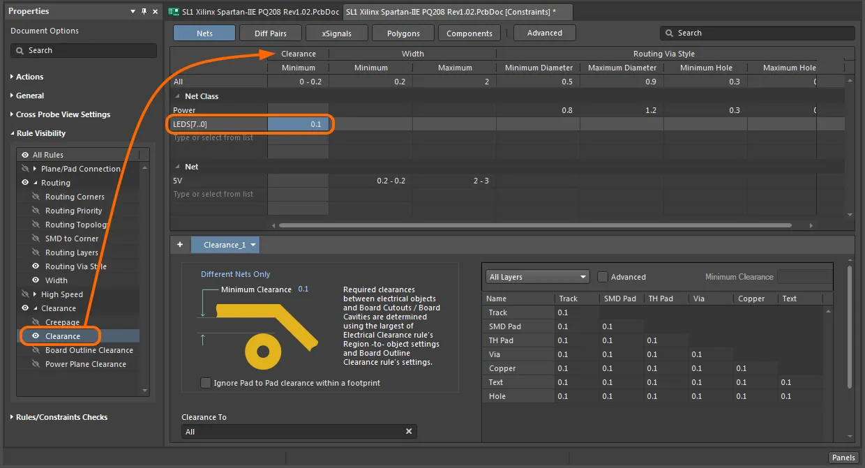
オブジェクト指向ビューで表示されるルールを選択します。
ルールの検証
すべてのアクティブなルールの有効性は、 Rules/Constraints Checks領域のPropertiesパネルで、 ボタンをクリックすることで確認できます。このアクションは、重複したルール、異なる値を持つ同じスコープのルール、クラスメンバー(ネットなど)が重複するルール、解決されていないスコープを持つルールなど、おそらくエラーとなるルールを検出します。各違反タイプのエントリーは展開して、違反しているルールを表示でき、選択すると、特定のルールエントリーが開きます。
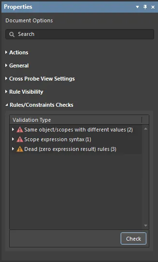
現在Constraints Editorで定義されているルールの有効性をチェックします。
ルール検証を実行するには、メインメニューからTools » Run Rules Validation Checkコマンドを使用することもできます
ルール違反
有効な設計制約ルールは、オンライン設計ルールチェック、バッチ設計ルールチェッカー、またはPCBルールと違反パネルから選択的に実行されるなど、さまざまなメカニズムを通じて現在のボード設計に適用されます。これらの制約ルールの違反 – 指定された範囲とスコープの限界を超える場合 – は、ボードのグラフィック、パネルエントリ、レポート、およびConstraints Editor内のアラートアイコンを通じて示されます。さらに、ボーナスとして、Constraints Editorが開いている間に、その設計ドキュメント(ダイアログ形式ではない)形式により、違反を検査、分析、修正することができます。

Constraints Editorは、違反しているルールに関するフィードバックを提供します。
Propertiesパネル
Constraints Editorが現在アクティブな場合、PropertiesパネルはDocument Optionsモード(またはエディターのAdvancedモードでのdvanced constraints optionsモード)を表示します。
以下の折りたたみセクションには、利用可能なオプションとコントロールに関する情報が含まれています:
アクション

-
Switch to Dialog View – コマンドを起動した後、ビューモードがDocument Viewから Dialog Viewに変更され、PCBルールとConstraints Editorダイアログが開きます。
一般

-
Show Default Values( Document Optionsモードのみ)- 有効にすると、エディターのグリッド領域のすべてのエントリーに適用可能なデフォルト値が薄いテキストとして表示されます。
-
Units - 希望する測定単位を選択します。測定単位は、Tools » Measurement Unitsメニューを使用しても選択できます。
クロスプローブビュー設定

-
Select – 有効にすると、フィルタリングされたオブジェクトが設計空間内で選択されます。
-
Zoom – 有効にすると(デフォルト)、フィルタリングされたオブジェクトが設計空間内でズームされ、中央に配置されます(可能な場合)。フィルタリングされたオブジェクトにズームインするために使用されるズームファクターを調整するには、Zoom Levelボタンを使用します。
-
Normal/Mask/Dim ドロップダウン – 設計空間内のフィルタリングされたオブジェクトとフィルタリングされていないオブジェクトを視覚的に区別するオプションを提供します。
-
Normal – フィルタリングされたオブジェクトが設計空間内で可視化され、フィルタリングされていないオブジェクトの外観は変わりません。
-
Mask – フィルタリングされたオブジェクトが設計空間内で強調表示され、他のすべてのオブジェクトがモノクロになります。
-
Dim – フィルタリングされたオブジェクトが設計空間内で強調表示され、他のすべてのオブジェクトはその色を保持しながら影をつけられます。
ルールの可視性

このPropertiesパネルの領域は、Document Optionsモードでのみ利用可能です。
-
グリッド - エディターのグリッド領域内でのルールタイプの利用可能性を設定するために使用します。
スコープライブラリ

このPropertiesパネルの領域は、Advanced constraints optionsモードでのみ利用可能です。
-
Scope – 定義されたすべてのスコープをリスト表示します。
-
Query – 関連するスコープに定義されたクエリを表示します。
-
Import – 選択されたスコープをConstraints Editorにインポートするために使用します。このオプションは、Constraints Editorにまだ存在しないスコープがダイアログで選択されている場合にのみ利用可能でアクセス可能です。
-
Export – 選択されたスコープをConstraints Editorにエクスポートするために使用します。
-
Edit Library – スコープライブラリダイアログを開くために使用します。ここでは、クエリベースのオブジェクトマッチングスコープを保存できます。カスタムスコープは、他のカスタム制約ルールでの再利用のためにインポート、管理、エクスポートが可能です。
ルール/制約チェック
ルール適用のチェック
Constraints Editorには、対応するPCBレイアウト内のネットと接続を視覚的にハイライト表示することで、制約ルールのオブジェクト範囲を示すクロスプローブ機能が含まれています。エディタのグリッドリスト内の任意のルールにクロスプローブするには、そのエントリを右クリックして、コンテキストメニューからCross Probeオプションを選択するか、高度なルールのメニューからCross Probeを選択します。
Cross Probe View Settings(ズームおよび選択オプション)をPropertiesパネルで設定し、PCBエディタのClear Filterオプションを使用してクロスプローブのハイライトをリセットします。 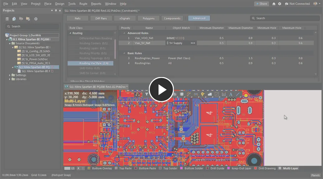
Constraints Editorからのルールの範囲内のオブジェクトへのクロスプローブ
