
인터랙티브 라우팅

Altium Essentials: PCB Routing
This content is part of the official Altium Professional Training Program. For full courses, materials and certification, visit Altium Training.

라우팅은 각 넷의 노드 사이에 연결 경로를 정의하는 과정으로, 트랙, 아크, 비아와 같은 PCB 설계 객체를 동박 레이어에 배치하여 노드 간에 연속적인 연결을 만듭니다. 이러한 객체를 하나씩 배치해 연결 경로를 구성하는 대신, 사용자는 연결을 interactively route합니다.
-
PCB 편집기에서 인터랙티브 라우팅은 지능적인 프로세스입니다. 인터랙티브 라우팅 명령을 실행한 후 패드를 클릭하면 라우팅할 연결이 선택됩니다. 커서를 패드에서 멀리 이동하면 인터랙티브 라우터가 해당 패드에서 현재 커서 위치까지의 라우트 경로를 정의하려고 시도합니다. 라우터가 정의하는 경로는 현재 corner style 및 gloss 설정을 포함한 여러 속성에 의해 제어됩니다.
-
배치되는 트랙/아크의 속성은 Routing Width 설계 규칙에 의해 제어되며, 다른 넷 객체와의 클리어런스는 전기적 Clearance 설계 규칙에 의해 제어됩니다.
-
컴포넌트 패드나 다른 넷의 배선처럼 보드에 이미 존재하는 객체에 대해 인터랙티브 라우터가 어떻게 반응하는지는 현재 Routing Conflict Resolution 모드에 따라 달라집니다. 이 모드는 라우터가 장애물을 Walkaround할지, 필요 시 객체를 Hug하거나 and Push할지, 또는 Push할지, Stop할지, Ignore할지를 결정합니다.
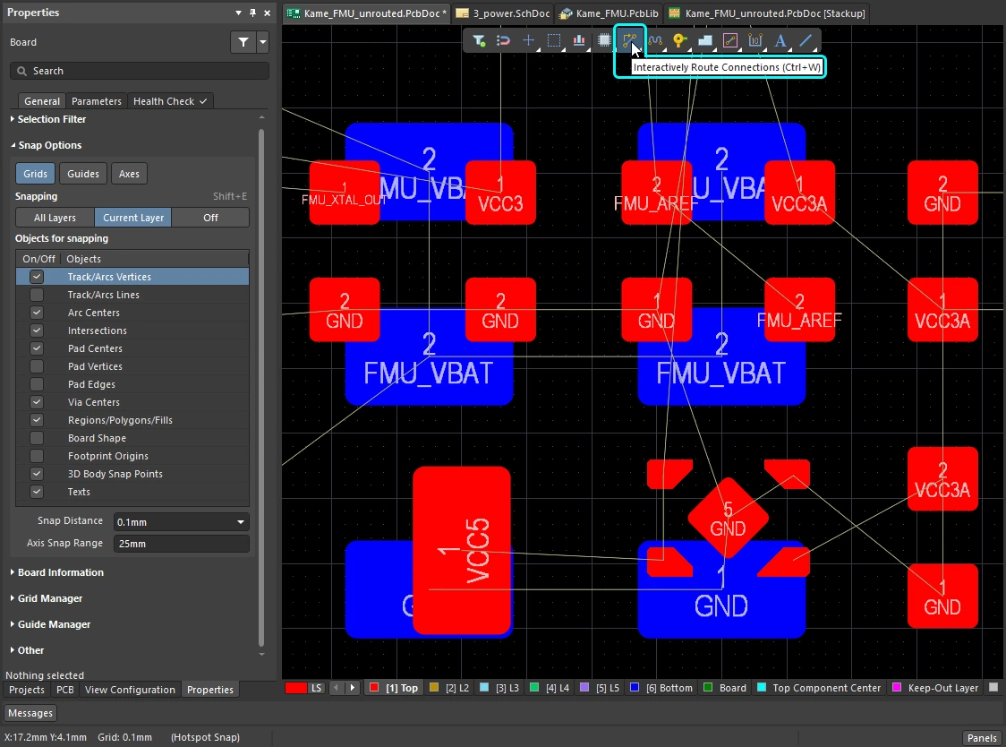
연결을 인터랙티브하게 라우팅하기 - 명령을 실행하고 연결선을 클릭하면 Interactive Router가 넷 객체에서 현재 커서 위치까지의 경로를 찾아 기존 객체를 피해가며 배선을 구성합니다. 마우스 버튼을 클릭하면 해칭된 모든 트랙 세그먼트가 배치되며, Ctrl+Click하여 라우트를 자동 완성할 수 있습니다.
인터랙티브 라우팅은 다음 대상에 대해 수행할 수 있습니다:
-
단일 넷 – Route » Interactive Routing
-
차동 페어로 구성된 두 개의 넷 – Route » Interactive Differential Pair Routing (자세히 알아보기)
-
선택된 넷 집합 – Route » Interactive Multi-Routing
라우팅 숙련도를 높이려면 PCB 설계 공간에서 객체가 어떻게 위치하는지를 잘 이해해야 하며, 다음 섹션에서는 이에 대한 개요를 제공합니다. 또한 조밀하게 배치된 설계 공간에서 현재 작업 중인 대상을 쉽게 볼 수 있도록 라우트의 표시를 제어하는 방법을 이해하는 것도 중요하며, 이에 대한 개요는 두 번째 섹션에 있습니다. 라우팅 숙련도를 높이는 세 번째 기술은 라우팅하면서 트랙과 비아의 속성을 제어하는 방법을 익히는 것입니다.
이러한 기술을 갖추고 라우팅 프로세스에 대해 더 알아보기 위해 이 페이지를 방문했다면, 인터랙티브 라우터 사용하기 섹션으로 바로 이동하세요.
설계 공간에서 객체가 위치하는 방식
PCB 편집기는 그리드 기반 편집 환경이며, 기본적으로 인터랙티브 라우팅은 현재 스냅 그리드 위에 배치됩니다. 스냅 그리드 외에도 소프트웨어에는 설계 객체를 정확하게 배치하고 정렬할 수 있도록 도와주는 여러 추가 스냅 기능이 포함되어 있습니다. 이러한 기능을 통틀어 Unified Cursor-Snap System라고 합니다.
커서 스냅 시스템에는 두 가지 핵심 요소가 있습니다. what커서가 무엇에 스냅되는지, 그리고 when언제 스냅되는지입니다.
-
What - 커서가 스냅되는 공간상의 지점에는 사용자 정의 Grids, 작업 Guides,, 그리고 기존 Objects의 스냅 포인트가 포함됩니다.
-
When - 커서는 스냅 포인트에 스냅됩니다. 즉, 커서가 Snap Distance 내에 있을 때, 그리고 해당 Layer에서 스냅이 허용될 때 스냅됩니다.
커서 스냅 기능 데모: Properties 패널에서 옵션을 설정하거나 Ctrl+E를 눌러 설정합니다.
무엇에 스냅되는가 |
|
| Snap to grids | 그리드는 카르테시안 및 극좌표 형식 모두에서 사용할 수 있습니다( |
| Snap to objects | 배치된 객체는 커서가 Snap Distance 안으로 이동하면 해당 객체의 스냅 포인트(핫스폿)에 대한 커서의 근접성을 기준으로 커서를 위치로 pull합니다. 예를 들어 트랙의 중심이나 그리드에서 벗어난 패드의 중심으로 커서를 끌어오는 데 사용할 수 있습니다. 객체 스냅은 모든 레이어, 현재 레이어만, 또는 비활성화로 적용할 수 있습니다. Shift+E 단축키를 사용해 모드를 순환 전환하고, 현재 모드는 상태 표시줄에서 확인할 수 있습니다( |
| Snap to guides | 수평, 수직, 대각선 및 포인트 가이드를 배치하여 위의 동영상과 같이 객체 정렬에 사용할 수 있습니다. 가이드에 대해 자세히 알아보세요. |
| Snap to object axes | 배치된 객체의 핫스폿이 Axis Snap Range 내에 있을 때 커서를 X 또는 Y 방향으로 끌어와 축 정렬되도록 하는 기능입니다 (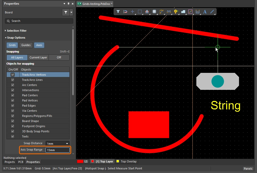 ). ). |
| Controlling the snapping |
|
 ).
). ).
). )
)Snapping to the Grid
| Toggle the units | Q 키를 눌러 단위를 Imperial과 미터법 사이에서 전환합니다. 그리드 단위는 변경되지만, 그리드 피치는 변경되지 않습니다. |
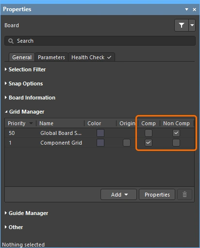
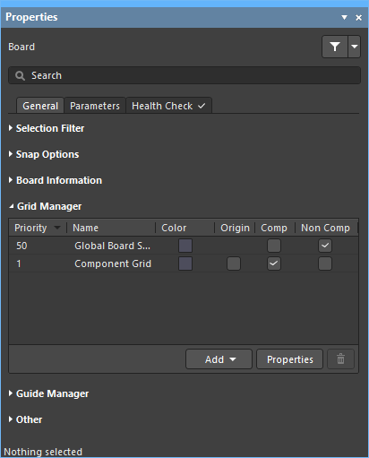
| Active grid? | 현재 커서 위치 아래에 여러 그리드가 정의되어 있는 경우, 가장 높은 우선순위의 그리드(가장 낮은 숫자 값)가 활성 그리드로 적용됩니다(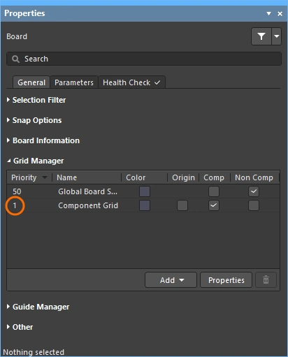 ). ). |
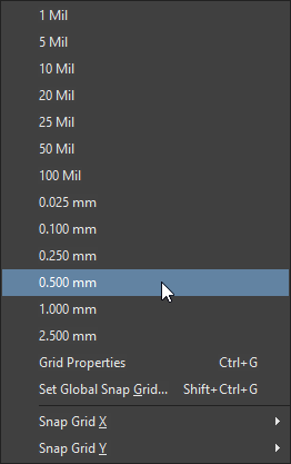
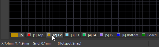
| Quickly select a grid | 미리 정의된 목록에서 그리드를 선택하려면 |
| Edit the grid value | 활성 그리드 값을 편집하려면 |
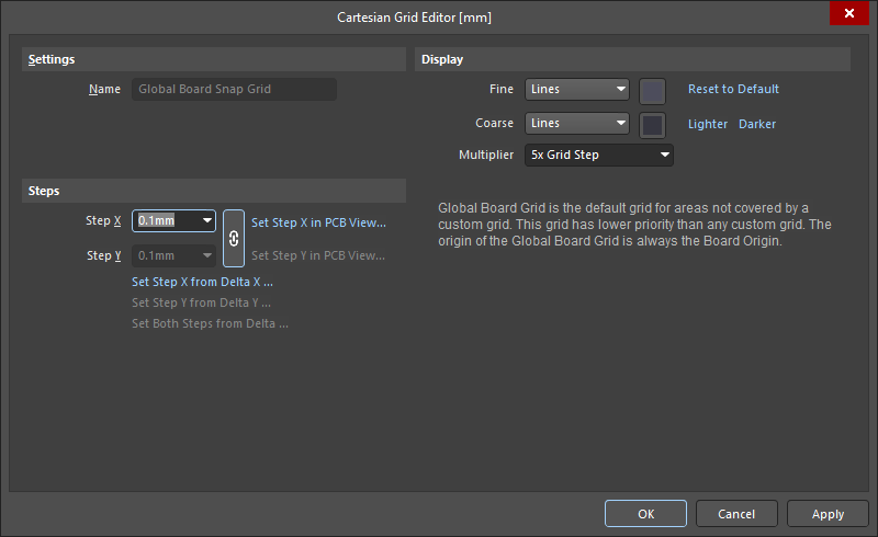
| Managing grids | 개별 그리드는 Grid Editor ( |
 ).
). ).
). )
)그리드 작업에 대해 자세히 알아보세요.
Snapping to Objects
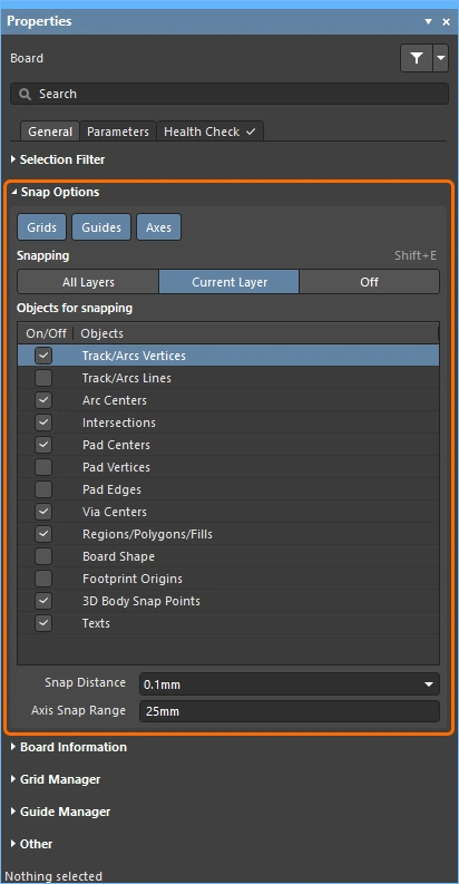
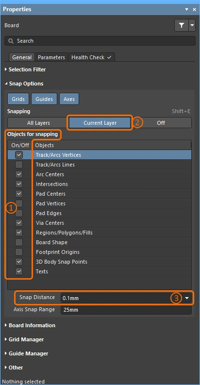
| Snap to objects | 커서는 다음 조건에서 스냅됩니다: 활성화된 Objects for snapping (1)이 있고, 활성화된 Snapping 레이어(2)에 있으며, 커서가 Snap Distance 이내에 있을 때입니다 (3)( |
| When to snap | 객체 스냅에는 Off, Current Layer, All Layers의 세 가지 상태가 있습니다. |
 ).
).Snapping to Guides and Axes
| To place a guide | 가이드를 배치하려면 Place » Work Guides 하위 메뉴 또는 Properties 패널의 Guide Manager 섹션을 사용합니다 ( |
| 가이드 속성 | 가시성, 색상 및 위치는 Properties 패널의 Guide Manager 섹션에서 관리합니다 (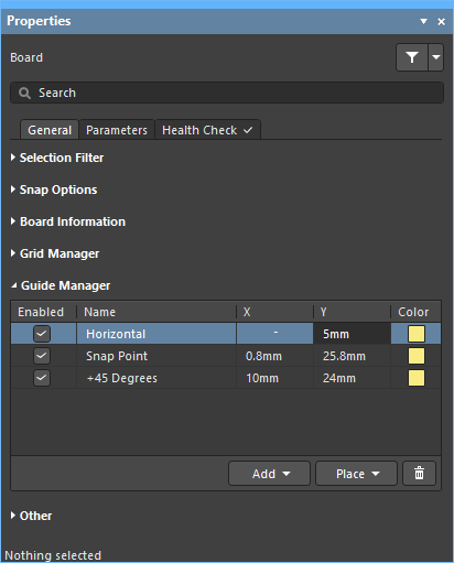 ). ). |
| 가이드에 스냅 | 가이드 스냅은 Guides 스냅 옵션이 활성화되어 있고 (1), 커서가 Snap Distance 이내에 있을 때 적용됩니다 (2) (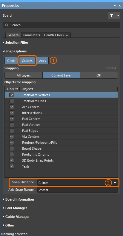 ). ). |
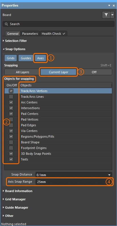
| Enabling axis snapping | 축 스냅은 Axes 스냅 옵션이 활성화되어 있고 (1), 활성화된 Objects for snapping (2)에 대해, 활성화된 Snapping 레이어(3)에 있으며, Axis Snap Range 이내에 있을 때 적용됩니다 (4)( |
 ).
).라우트 표시 제어
인쇄 회로 기판 설계는 종종 매우 조밀하고 객체로 복잡하게 채워져 있습니다. 소프트웨어에는 레이어 가시성, 마스킹 및 디밍, 객체 가시성 및 투명도를 비롯해 객체 표시를 관리하는 데 도움이 되는 여러 기능이 있습니다.
하이라이트, 객체 및 레이어 제어 기능을 사용하여 설계를 더 쉽게 파악하세요.
| Single layer mode | Shift+S를 눌러 표시를 단일 레이어 모드로 전환합니다. 사용 가능한 모드는 3가지이며, Preferences 대화상자의 PCB Editor – Board Insight Display 페이지에서 원하는 모드를 활성화할 수 있습니다 (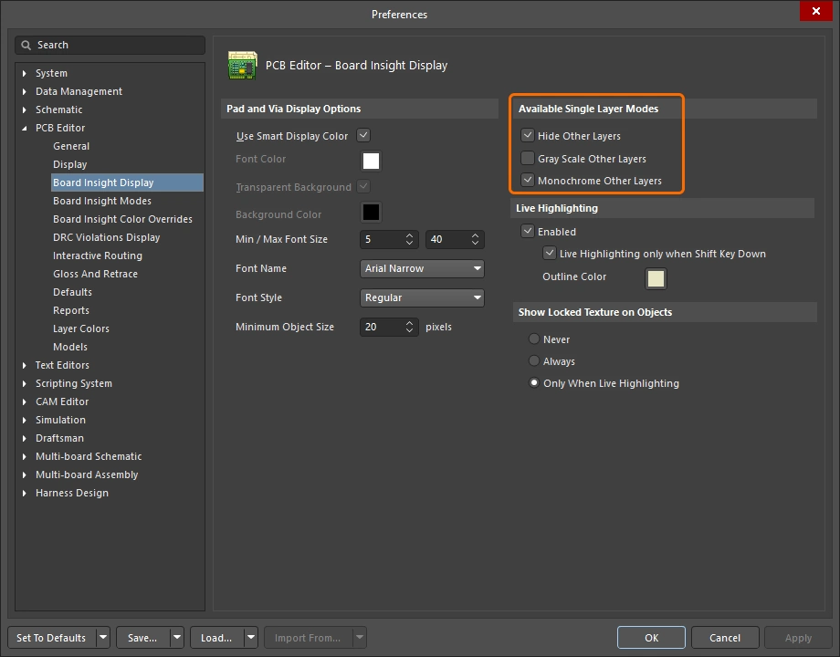 ). ). Shift+S를 누를 때마다 다음 활성화된 단일 레이어 모드로 전환되며, 마지막에는 현재 활성화된 모든 레이어 표시로 돌아갑니다. |
| Layer sets | 미리 정의된 가시 레이어 집합을 구성한 다음 편집 창 왼쪽 하단의 Manage Layer Sets 버튼을 사용해 선택할 수 있습니다 (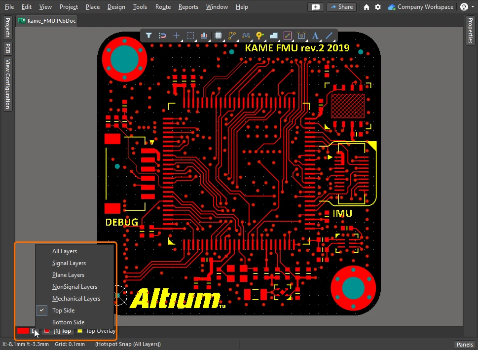 ). 새 집합은 View Configuration 패널에서 정의하며, 이는 위의 동영상에 시연되어 있습니다. ). 새 집합은 View Configuration 패널에서 정의하며, 이는 위의 동영상에 시연되어 있습니다. |
| Dim or Mask to fade | 관심 있는 객체(예: 부품, 넷, 차동 페어 또는 모든 유형의 클래스)를 빠르게 강조 표시하려면 PCB 패널에서 해당 객체를 찾은 다음 Dim 또는 Mask 모드(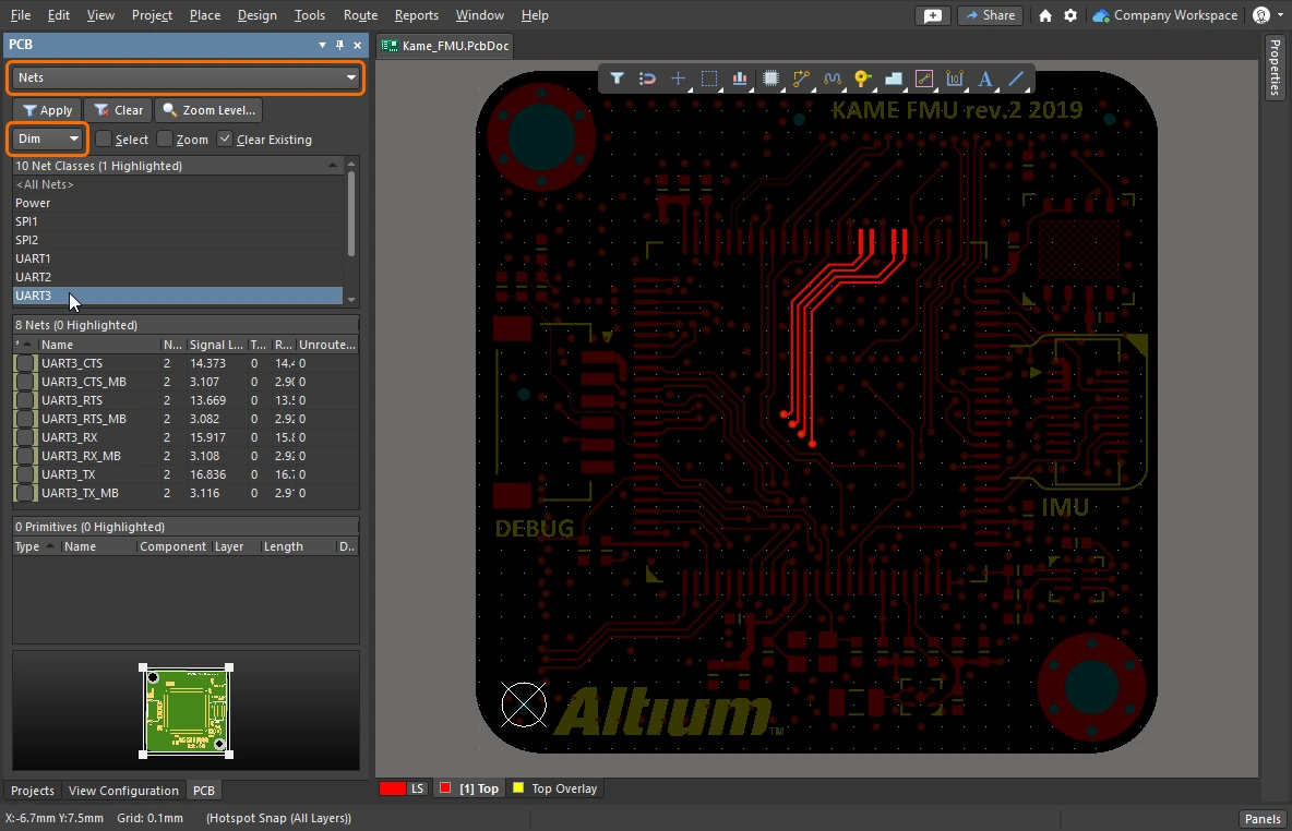 )를 활성화합니다. 이 두 모드는 관심 있는 객체except를 제외한 모든 객체를 흐리게 표시하여, 관심 객체가 더 두드러지게 보이도록 합니다. Dim 및 Mask 수준은 View Configuration 패널( )를 활성화합니다. 이 두 모드는 관심 있는 객체except를 제외한 모든 객체를 흐리게 표시하여, 관심 객체가 더 두드러지게 보이도록 합니다. Dim 및 Mask 수준은 View Configuration 패널(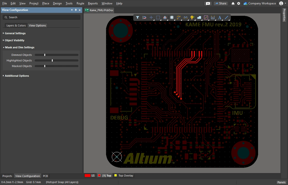 )에서 구성합니다. )에서 구성합니다. |
| Clearance boundaries | 이 옵션을 활성화하면 전기적 객체 주변에 필요한 클리어런스를 표시합니다. ( |
| Object transparency | 각 객체 유형의 투명도 수준은 View Configuration 패널( |
| The visibility of objects | 관심 없는 객체를 숨기면 설계 공간을 깔끔하게 정리하는 데 편리합니다 (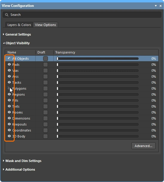 ). 객체는 숨겨져 있어도 여전히 제약 시스템의 검사 대상이 됩니다. 폴리곤을 표시에서만이 아니라 제약 시스템and에서도 제외하려면, 대신 Shelve를 사용하십시오. ). 객체는 숨겨져 있어도 여전히 제약 시스템의 검사 대상이 됩니다. 폴리곤을 표시에서만이 아니라 제약 시스템and에서도 제외하려면, 대신 Shelve를 사용하십시오. |
| Displaying net names | View Configuration 패널(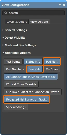 )에서 패드, 비아 및 트랙에 표시되는 넷 이름의 표시 옵션을 구성합니다. 넷 이름은 항상 각 트랙 세그먼트의 중앙에 표시되며, 필요하면 반복 표시할 수 있습니다. 표시 글꼴 속성은 Preferences 대화상자( )에서 패드, 비아 및 트랙에 표시되는 넷 이름의 표시 옵션을 구성합니다. 넷 이름은 항상 각 트랙 세그먼트의 중앙에 표시되며, 필요하면 반복 표시할 수 있습니다. 표시 글꼴 속성은 Preferences 대화상자(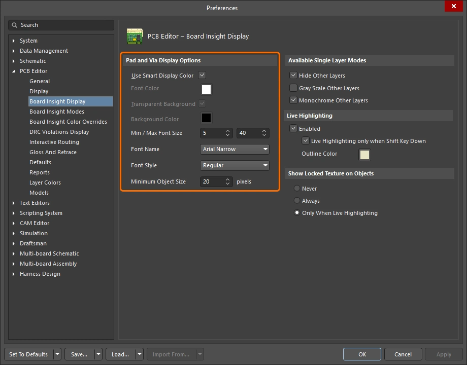 )의 PCB Editor – Board Insight Display 페이지에서 구성합니다. )의 PCB Editor – Board Insight Display 페이지에서 구성합니다. |
배선 속성 제어
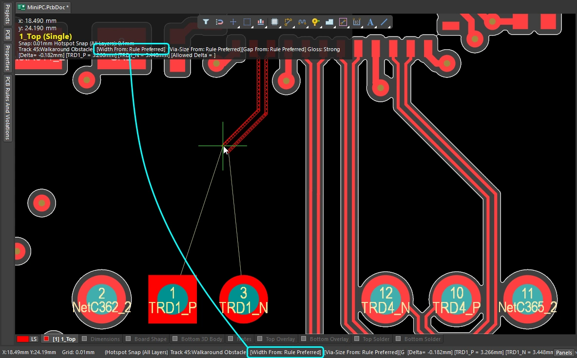
클리어런스, 라우팅 폭 및 라우팅 비아 스타일 설계 제약을 구성했다면 이제 라우팅할 준비가 되었습니다. 라우팅을 시작하기 위해 클릭하면, 라우터는 어떤 트랙 폭을 사용해야 하는지, 그리고 레이어를 전환할 때 어떤 비아 크기를 사용해야 하는지를 어떻게 알 수 있을까요?
라우팅 준비를 설정한 다음, 라우팅 중 라우팅 폭과 비아 스타일을 선택하는 간단한 데모입니다.
 ).
).Changing the Routing Width (0:29)
 )
) ).
). )
) )
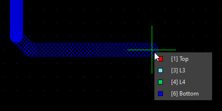
)Changing the Routing Layer (1:14)
 ).
). ).
).Changing the Via (1:22)
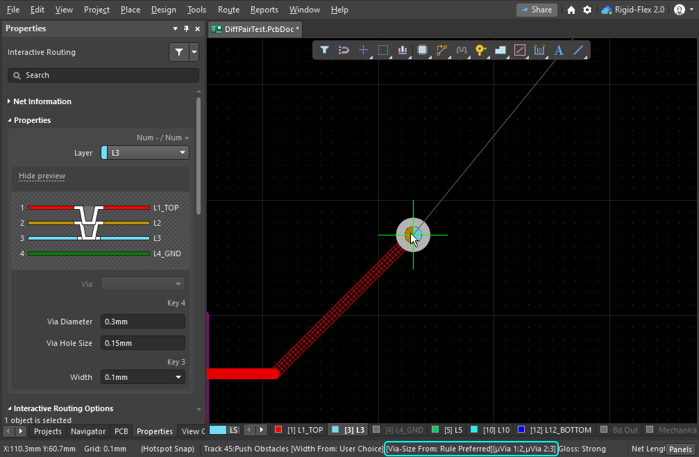
| Routing via | 라우팅 중 레이어를 전환하면, 적용 가능한 Routing Via Style 설계 제약에 따라 비아가 자동으로 추가됩니다. |
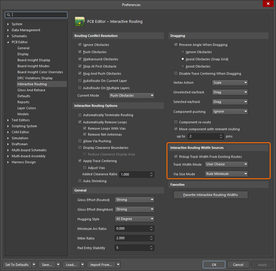
| Default routing via | 레이어 변경 중 사용되는 비아의 크기는 Interactive Routing Width Sources 옵션( |
| Cycle available via sizes | 라우팅 중 4를 눌러 Minimum, Preferred 또는 Maximum 비아 크기 설정(적용 가능한 Routing Via Style 설계 제약에 정의됨) 사이를 순환 전환하거나, User 비아 크기를 선택할 수 있습니다 (
). 마지막 상태는 현재 Via Size Mode로 유지됩니다. 현재 비아 크기 모드는 상태 표시줄과 heads-up display(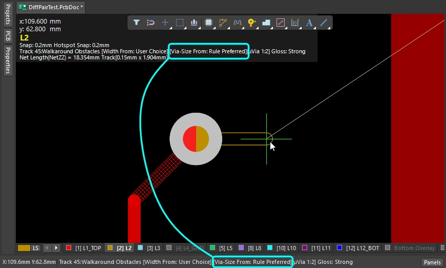 )에 표시됩니다. )에 표시됩니다. |
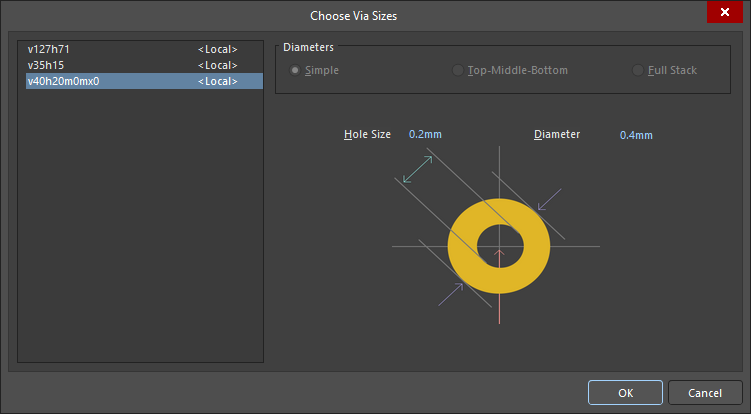
| Choose a different User via size | 또는 라우팅 중 |
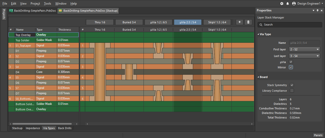
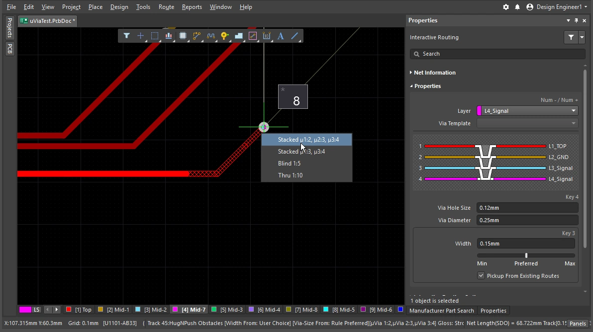
| Cycle the via span | 비아가 관통하는 레이어는 현재 Via Type에 따라 결정되며, 사용 가능한 비아 유형은 Layer Stack Manager( |
 )
) )
) ).
). ).
). )
)비아에 대해 자세히 알아보십시오.
자세한 내용은 비아 유형 정의하기를 참조하세요.
인터랙티브 라우터 사용하기
인터랙티브 라우팅 명령을 실행하고 패드나 연결선을 클릭하면 어떤 일이 일어날까요? 인터랙티브 라우팅 엔진은 클릭 위치에 가장 가까운, 해당 넷에 속한 구리 요소(패드, 비아, 트랙)에서 현재 커서 위치까지의 경로를 찾으려고 시도하며, 지정된 폭의 트랙/아크를 배치하고 현재 라우터 설정에 따라 깔끔한 패턴으로 배선합니다.
라우트는 SMD 패드에서 어떻게 빠져나갈까요? 장애물을 만나면 라우팅은 어떻게 반응할까요? 그 장애물을 우회할까요, 밀어낼까요, 아니면 무시할까요? 코너는 어떤 형태를 취하며, 다른 부품의 패드 사이를 어떻게 통과할까요? 앞 절에서 라우트 자체의 속성 제어 방법을 설명했다면, 이 절에서는 라우트가 배선 공간을 지나갈 때 이를 제어할 수 있는 기능을 요약합니다.
인터랙티브 라우터 사용하기 |
|
| Hatched/solid/hollow track/arc segments | 해치 처리된 트랙/아크는 아직 배치되지 않은 상태이고, 실선 트랙/아크는 배치된 상태입니다( 커서에 연결된 트랙이 속이 빈 상태(해치도 아니고 실선도 아님)일 때, 이를 look-ahead segment라고 합니다. 다음 클릭 시 이 구간은 배치되지 않습니다. 이 기능을 사용하면 마지막 세그먼트를 배치하겠다고 확정하지 않고도 이전 세그먼트의 끝점을 위치시킬 수 있습니다( |
| How the router forms the corners | 인터랙티브 라우팅 중 트랙과 아크가 만들어내는 코너의 형태를 corner style라고 합니다. 대각선 코너가 가장 일반적이지만, 아크를 배치해 만드는 곡선 코너도 많이 사용됩니다. 사용할 수 있는 코너 스타일은 5가지이며, 그중 4가지는 코너 방향 하위 모드도 제공합니다.
|
| How the routing leaves a pad | 인터랙티브 라우팅 엔진이 패드에서 나가거나 패드로 들어가는 방식은 다음 항목으로 제어됩니다.
|
| How the route reacts to an existing object | 이는 현재 Conflict Resolution Mode 설정에 따라 결정됩니다. 현재 충돌 해결 모드는 상태 표시줄( |
| 새 라우팅의 매끄러움 | 커서를 처음 클릭한 위치에서 멀리 이동하면, 라우팅은 객체 주변에서 최적의 경로를 찾도록 형태를 바꾸며 현재 커서 위치에 도달하려고 합니다. 그 경로의 정돈 정도, 즉 품질은 현재 glossing setting에 의해 결정됩니다. 글로싱은 라우팅 품질을 향상시키는 도구 모음으로, 경로 길이를 줄이고 코너 형상을 개선하며 코너 수를 줄이려고 시도합니다. 또한 직각을 피하고 T-접합부와 패드에서 예각이 생기지 않도록 합니다. 글로싱은 차동 페어도 지원하며, 길이와 간격이 균형 잡힌 페어 구간을 늘리도록 시도합니다. 글로싱에는 Off, Weak, Strong의 세 가지 설정이 있습니다. 인터랙티브 라우팅 또는 인터랙티브 슬라이딩 중에는 |
| Auto-complete the connection | 넷을 인터랙티브하게 라우팅하는 동안
연결을 자동 완성할 수 없는 경우, 도구는 마지막으로 사용한 인터랙티브 라우팅 모드로 돌아갑니다. |
| Center the routes between pads / vias | 인터랙티브 라우터는 설계 제약을 준수하며, 가장 가까운 패드로부터 허용되는 최소 클리어런스를 유지하면서 한 쌍의 패드 사이를 자동으로 라우팅합니다. 라우트가 패드 사이의 중앙으로 이동해 간격을 두도록 하려면 Apply Trace Centering 옵션을 구성하세요. 임의의 패드 쌍, 비아 쌍 또는 패드/비아 쌍 사이에서도 이를 달성할 수 있도록, 이 기능은 라우팅 클리어런스를 지능적으로 증가시킬 수 있는 클리어런스 배수를 사용합니다. |
| Auto-narrow the route | 좁은 틈을 통과하도록 라우트를 가늘게 만드는 것은 때로는 그 넷을 라우팅하는 유일한 방법입니다. Auto Shrinking 기능은 이를 수행할 수 있으며, 라우트를 틈에 딱 맞도록 자동으로 좁혀 줍니다. 이때 허용되는 최소값은 라우팅 폭 제약에 의해 정의됩니다. |
| Route selection strategies | 작업할 라우트를 선택하는 것은 라우팅의 핵심 요소입니다. 라우트를 선택해 언라우트하거나, 글로싱을 적용하거나, 속성을 확인하거나, 삭제할 수 있습니다. |
 ).
). ).
). )
)Responding to Obstacles – Conflict Resolution Mode
인터랙티브 라우팅 명령을 실행하고 패드를 클릭합니다. 커서를 패드에서 멀리 이동하면 인터랙티브 라우팅 엔진은 클릭한 패드에서 현재 커서 위치까지 해치 처리된 트랙 세그먼트 경로를 생성하며, 커서를 움직이면 설계 제약과 현재 글로싱 설정에 따라 라우트 경로를 가장 잘 정의하도록 해치 세그먼트를 계속 업데이트합니다.
패드나 다른 넷의 라우팅처럼 PCB 작업 공간에 이미 있는 객체에 인터랙티브 라우터가 어떻게 반응하는지는 현재 routing conflict resolution 모드에 따라 달라집니다. 라우팅 충돌 해결 모드는 인터랙티브 라우팅 엔진이 해당 장애물을 밀어내려고 할지, 우회할지, 아니면 단순히 무시하고 그 위로 라우팅할지를 결정합니다.
충돌 해결 모드별 동작 차이를 간단히 보여주는 예시입니다.
Routing Conflict Resolution Mode |
|
| Current mode | 현재 라우팅 충돌 해결 모드는 Heads-up 디스플레이( |
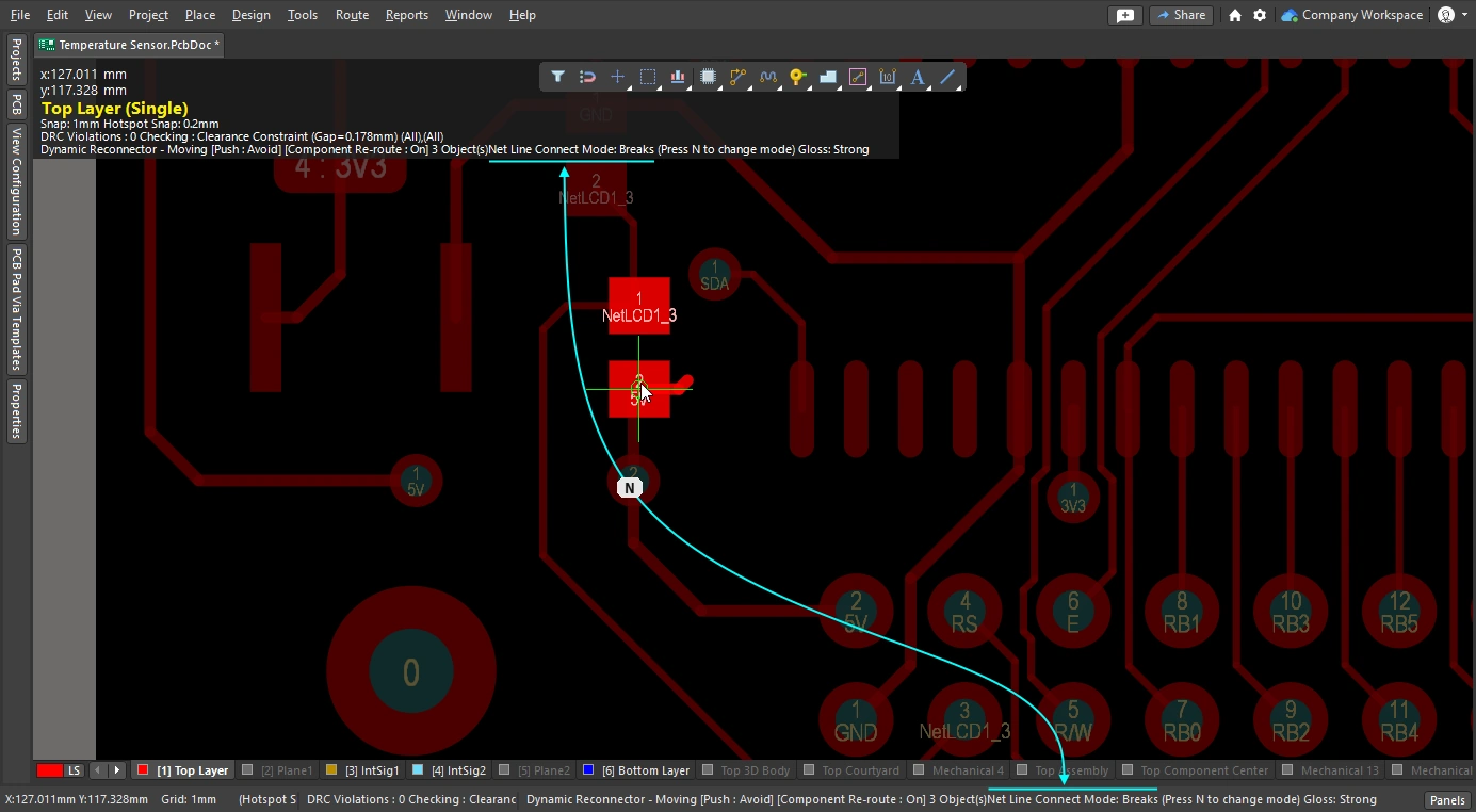
| Changing modes | 인터랙티브 라우팅 중(또는 인터랙티브 슬라이딩이나 비아 드래깅 중) 모드를 변경하려면 Shift+R 단축키를 누르세요. |
| Available modes | 개별 충돌 해결 모드는 Preferences 대화상자의 PCB Editor – Interactive Routing 페이지에서 활성화/비활성화할 수 있습니다( |
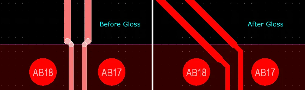
Glossing during Routing
인터랙티브 라우터가 마지막 클릭 위치부터 현재 커서 위치까지 경로를 찾고 트랙 세그먼트를 배치하는 것뿐 아니라, 그 라우트 경로가 가능한 한 짧고 최소한의 트랙 세그먼트로 구성되기를 원할 것입니다. 이 과정을 관리하기 위해 PCB 편집기에는 Glossing 도구가 포함되어 있습니다.
글로싱은 적용 가능한 설계 규칙의 의도를 존중하면서 더 깔끔한 라우팅과 패드 엔트리를 생성하도록 특별히 개발된 정교한 알고리즘 집합입니다. 글로싱은 경로 길이를 줄이고 코너 형상을 개선하며 코너 수를 줄이려고 시도하므로, 일반적으로 더 적은 세그먼트로 더 정돈된 라우팅이 만들어집니다. 또한 글로싱은 서브넷 점퍼는 기존 상태 그대로 두며, 공간 기반 폭 규칙이 있는 경우 경계에서의 폭 변경도 존중합니다. 새 인터랙티브 라우트 경로를 정의하는 동안 커서를 움직이면, 아직 확정되지 않은 모든 라우팅에도 자동으로 글로싱이 적용됩니다.
라우팅 중인 넷에 글로싱을 적용하는 것뿐 아니라, 인터랙티브 라우팅 엔진은 현재 라우팅 중인 넷의 영향을 받는 인접(이웃) 넷에도 글로싱을 적용할 수 있습니다.
글로싱이 꺼진 경우와 켜진 경우의 차이를 간단히 보여주는 예시입니다.
글로싱 이해하기 |
|
| When does glossing run | 글로싱 도구는 다음과 같이 실행됩니다.
|
| How strong is glossing | 배선이 얼마나 강하게 글로싱되는지는 현재 Gloss Effort (Routed) 설정으로 제어됩니다. 이 옵션은 (
|
| Glossing the neighbors | Push 또는 Hug & Push 인터랙티브 라우팅이나 슬라이딩 중에는 인접한 배선, 즉 이웃 배선이 영향을 받습니다. 이 이웃 배선들도 Gloss Effort (neighbor) 설정에 따라 글로싱될 수 있습니다(  ). Gloss effort (neighbor) 설정 ). Gloss effort (neighbor) 설정 |
| Hugging - how glossing wraps around other objects and forms corners | 글로싱 엔진이 다른 객체를 피해 배선을 감싸고 코너를 형성하는 방식은 hugging라고 합니다. 사용 가능한 Hugging Style 설정은 다음과 같습니다.
|
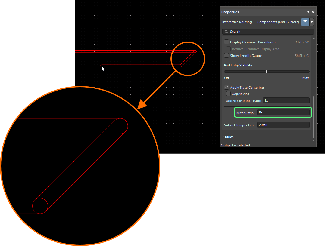
| Controlling the properties of the corner | 코너가 직선 트랙 세그먼트로 형성되는 경우, 기본적으로 글로싱 엔진은 90도 코너에 작은 마이터를 적용하며, 그 크기는 Miter Ratio 설정으로 제어됩니다. Miter ratio 설정 코너가 아크로 형성되는 경우 최소 아크 크기는 Minimum Arc Ratio로 제어됩니다. Minimum Arc Ratio는 Any Angle 인터랙티브 라우팅 중에도 적용되며, Mixed Hugging Style을 사용하는 인터랙티브 슬라이딩 중에도 적용됩니다. 이 비율은 허용되는 최소 아크 반경을 결정하는 데 사용되며, 아크 반경이 이 최소값보다 작아지면 해당 아크는 트랙 세그먼트로 대체됩니다. Minimum arc ratio 설정 |
| Inhibit glossing during routing and sliding | 글로싱을 일시적으로 끄고 싶을 때가 있을 수 있습니다. 라우팅 중에는 Ctrl+Shift 단축키를 눌러 유지하면 글로싱을 억제할 수 있으며, 키를 놓는 즉시 현재 Routing Gloss Effort 설정으로 글로싱이 다시 시작됩니다. 이 상태는 상태 표시줄에 반영되지 않으며, 마지막으로 선택된 상태가 계속 표시된다는 점에 유의하십시오. |

 ).
).

아래 슬라이드는 서로 다른 Gloss Effort (Routed) 및 Gloss Effort (Neighbor) 설정의 간단한 예를 보여줍니다.
Miter or Curve the Corners
코너는 짧은 직선 트랙 세그먼트(마이터)로 정의할 수도 있고, 하나 이상의 아크를 사용해 만들 수도 있습니다. 아래 이미지는 가장 널리 사용되는 두 가지 코너 스타일인 Track 45 및 Any Angle를 보여줍니다.


마이터 코너
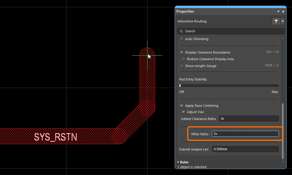
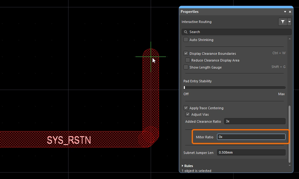
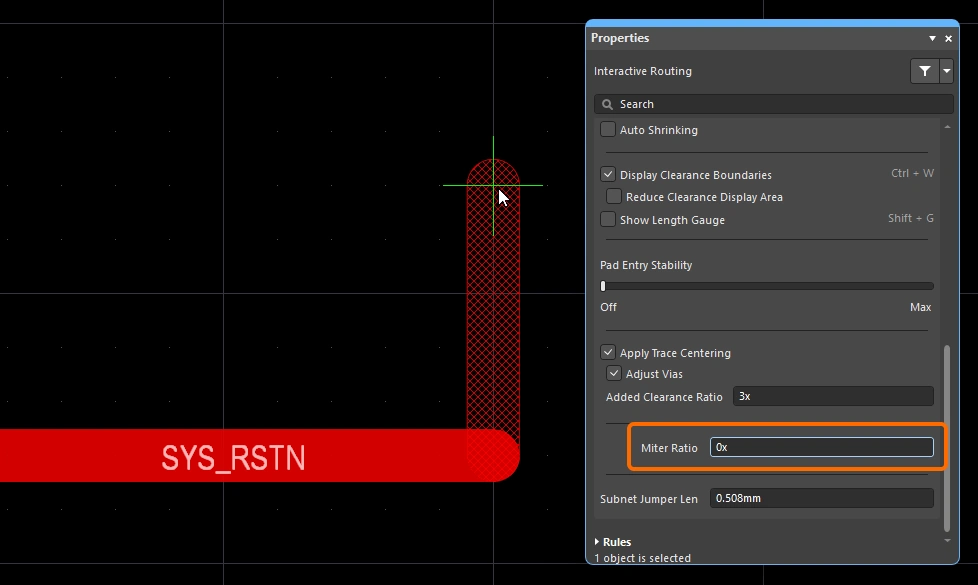
가장 일반적인 라우팅 코너 형상은 45도 마이터(대각선) 코너입니다. 대각선 코너로 라우팅하려면 Track 45 corner mode로 전환하십시오. 여기에 더해, 인터랙티브 라우팅 엔진에는 miter ratio 기능도 포함되어 있어, 촘촘한 코너에서도 마이터가 유지되도록 하며 라우팅 중 실수로 직각 또는 예각 코너가 만들어지는 것을 방지합니다.
Miter Ratio 는 다음과 같이 정의됩니다:
Miter Ratio x current track width = separation between the walls of the tightest U-shape that can be routed for that miter ratio
 miter ratio는 코너에 자동으로 추가되는 최소 마이터 크기를 제어합니다.
인터랙티브 라우팅과 인터랙티브 슬라이딩 모두 Miter Ratio 옵션을 포함합니다. 0 이상의 양수를 입력하십시오. Miter Ratio 옵션의 값을 다르게 설정하여 동일한 트레이스를 라우팅한 예시는 아래에 나와 있습니다.

 )
) 값을 구성하거나, Preferences 대화상자
 )
) )
) ).
).곡선 코너
많은 설계자가 곡선 코너를 필요로 합니다. 곡선 코너는 라우팅하면서 배치할 수 있으며, Line 45/90 With Arc 코너 모드 또는 Line 90/90 With Arc 코너 모드를 사용할 수 있습니다. 다만 Line 90/90 With Arc 코너 모드는 90도 코너를 강제하므로, 배선이 45도로 계속 진행되어야 한다면 Line 45/90 With Arc 코너 모드를 사용하십시오. 아크는 라우팅 중 ![]() 및
및 ![]() 키를 사용해 인터랙티브하게 크기를 조정할 수 있습니다(
키를 사용해 인터랙티브하게 크기를 조정할 수 있습니다(Shift를 누른 채로 있으면 크기 조정이 더 빨라집니다).
인터랙티브 라우팅 중 곡선 코너 스타일이 선택되면, 글로싱 엔진은 기존의 곡선 객체를 따라 접선 경로를 우선시합니다. 즉, 코너를 만들기 위해 배치되는 아크는 기존 객체를 정확히 감아 돌 수 있도록 위치와 반경이 설정됩니다. 이는 예를 들어 BGA 아래의 escape via 패턴처럼 곡선 형상이 많은 영역에서 부드러운 라우팅을 형성하도록 설계된 것입니다. Routing Gloss Effort이 Strong로 설정되어 있으면 아크 사이의 직선 트랙 세그먼트가 수평 또는 수직이 아닌 각도로 배치될 수 있습니다.
모든 직선 트랙 세그먼트를 정확히 수평 또는 수직으로 유지하면서 곡선 코너를 원한다면, 대각선 코너로 먼저 라우팅한 후 글로싱으로 코너를 곡선화하는 것이 더 효율적일 수 있습니다. 이를 위해 Hugging Style를 Rounded로, Gloss Effort를 Weak로 설정한 다음, 해당 배선을 선택한 상태에서 Gloss Selected 명령을 실행하십시오.
기존 배선의 코너를 곡선화하려면 Hugging Style을 Rounded로, Gloss Effort를 Weak로 설정한 다음 배선을 선택하고 Route » Gloss Selected 명령을 실행하십시오.
스네이크 라우팅
앞서 설명한 아크 코너 모드 사용 외에도, 코너 스타일을 Any Angle로, Routing Gloss Effort를 Strong로 설정하면 부드럽게 흐르는 point-to-point 라우팅 스타일을 구현할 수 있습니다. 이렇게 하면 Snake Routing라고 하는 라우팅이 만들어집니다. 아래 예시 비디오와 같이 여러 곡선 객체 사이를 Any Angle 배선으로 자연스럽게 통과해야 하는 경우에 사용하십시오.
스네이크 라우팅 – 코너 스타일은 Any Angle로 설정됩니다.
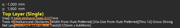
Using the Net Length Gauge
Length 제약 및/또는 Matched Length 제약이 정의되어 있으면, Length Tuning Gauge를 표시하여 대화형 라우팅(및 대화형 길이 튜닝) 중에 길이를 모니터링할 수 있습니다. 라우팅하는 동안 Shift+G 단축키를 사용해 Gauge 표시를 켜거나 끌 수 있습니다.
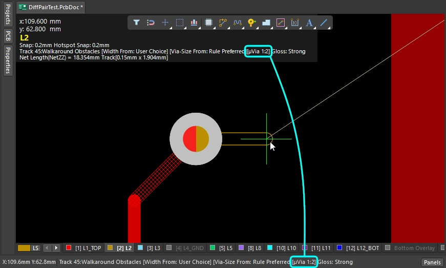
Gauge는 Current Routed Length를 숫자로 표시하고, 빨간색/초록색 슬라이더는 Estimated Length를 표시합니다. 대화형 라우팅 중에는 Routed Length가 아직 제약의 최소값에도 도달하지 않았는데도 Gauge 슬라이더가 제약의 최소값과 최대값 사이 어딘가에 있는 것이 아래 이미지처럼 혼란스럽게 보일 수 있습니다. 이는 대화형 라우팅 중 슬라이더가 Estimated Length를 나타내기 때문이며, 여기서:
Estimated Length = Routed Length + distance to target (length of connection line)
 Gauge는 대화형 라우팅 중 Length 설계 제약이 준수되고 있음을 보여줍니다. 현재 Routed length는 숫자로 표시되고, 슬라이더는 현재 Estimated Length를 표시합니다.
Gauge는 다음과 같이 동작합니다.
-
Gauge의 외곽을 정의하는 직사각형 상자.
-
허용되는 최소 및 최대 길이를 나타내는 두 개의 노란색 세로 막대. 최소값과 최대값은 위에서 설명한 대로 설계 제약으로 정의된 제약 조건들 중 가장 엄격한 집합에 의해 결정됩니다.
-
목표 길이를 나타내는 초록색 세로 막대. 이는 수동으로 입력한 값이거나, 기존에 선택된 net의 길이를 사용한 값이거나, 설계 제약에서 계산된 경우 유효 길이 범위의 중간값입니다.
-
현재 net의 Routed Length(길이 튜닝 중) 또는 Estimated Length(대화형 라우팅 중)를 표시하는 빨간색 또는 초록색 슬라이더. 현재 길이가 허용 범위를 벗어난 상태에서 허용된 최소/최대 길이 범위 내로 들어오면 슬라이더 색상이 빨간색에서 초록색으로 바뀝니다.
-
현재 Routed Length(배치된 트랙과 아크의 길이) 는 Gauge 슬라이더 위에 숫자 값으로 겹쳐 표시됩니다(예시 이미지에서는 62.781mm).
-
Gauge의 직사각형 외곽선은 가능한 전체 길이 범위를 나타내며, 상한과 하한의 의미는 선택한 target length 모드에 따라 달라집니다.
-
모드가 Manual 또는 From Net이고 적용 가능한 Length 제약이 없는 경우, 슬라이더 박스의 하한은 현재 net의 길이가 되고 상한은 지정된 Max Length가 됩니다.
-
모드가 Manual 또는 From Net이고 적용 가능한 Length 제약이 있는 경우, 슬라이더 박스의 하한은 제약 값 또는 현재 라우트 길이 중 더 작은 값에서 가져오며, 상한은 사용자가 정의합니다.
-
모드가 From Rule이고 적용 가능한 Length 제약, 적용 가능한 Matched Length 제약 또는 이 둘의 조합이 있는 경우, 슬라이더 박스의 하한은 제약 값 또는 현재 라우트 길이 중 더 작은 값으로 결정되고, 슬라이더 박스의 상한은 제약의 MaxLimit로 결정됩니다.
-
Routing Pad Entries
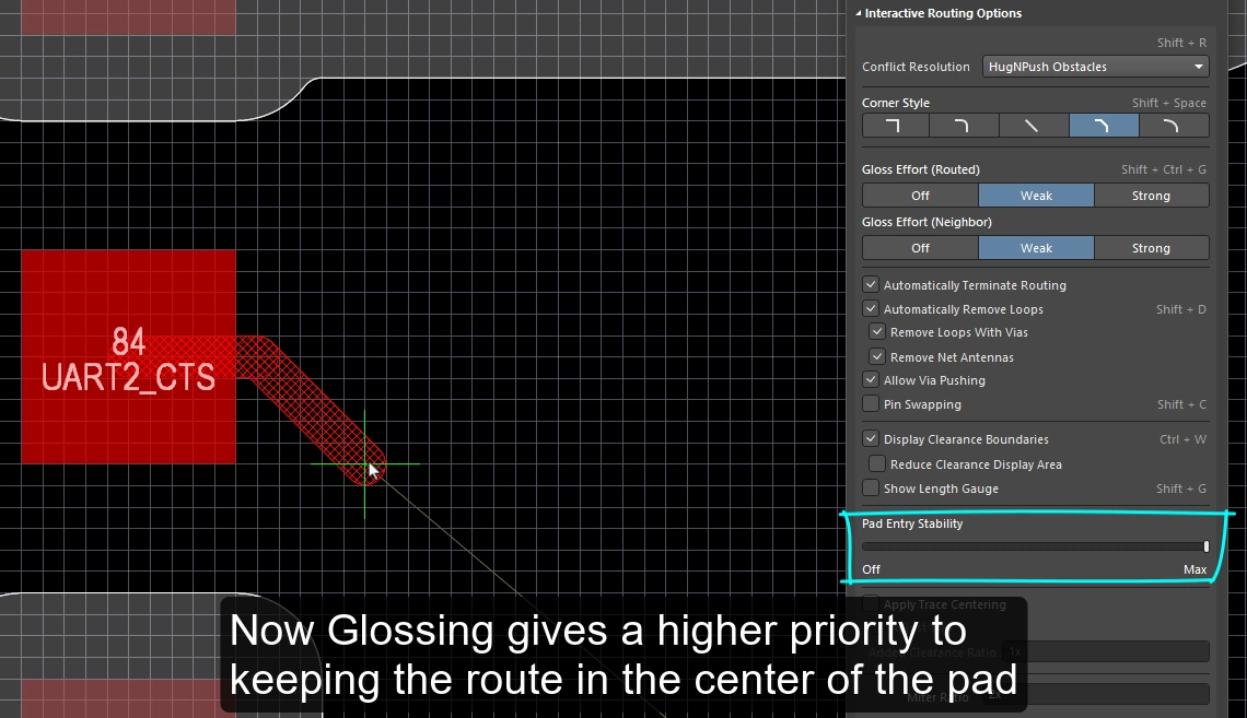
대화형 라우팅 엔진은 적용 가능한 SMD pad entry 설계 제약에 따라 표면실장 패드에 진입하고 빠져나갑니다. 라우팅하거나(또는 라우트를 슬라이드할) 때, 현재 gloss strength 설정에 따라 exit / entry가 지속적으로 글로싱됩니다. 글로싱은 더 깔끔한 라우팅과 pad entry를 생성하면서 적용 가능한 설계 규칙의 의도를 존중하도록 특별히 개발된 정교한 알고리즘 집합입니다. 글로싱 엔진에는 또한 Pad Entry Stability 기능이 포함되어 있어, 설계자가 글로싱 엔진이 pad centerline을 우선하도록 지시할 수 있습니다.
SMD Pad Entry 설계 제약
SMT Design Constraints는 대화형 라우터가 표면실장 패드에 어떻게 진입하고 빠져나갈지를 제어하며, 라우팅 프로세스를 시작하기 전에 구성해야 합니다. 이러한 설계 규칙을 생성하고 설정하려면 PCB Rules and Constraints Editor dialog를 여십시오(메인 메뉴에서 Design » Rules 클릭).
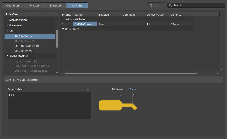
| SMD to Corner | 이 제약은 첫 번째 코너가 위치한 버텍스 중심까지의 거리를 패드 가장자리로부터 정의합니다. 이 값은 트랙 폭 또는 적용 가능한 clearance 규칙 중 더 큰 값보다 커야 합니다. 이보다 작아야 한다면 다음 세 가지 방법으로 접근할 수 있습니다.
|
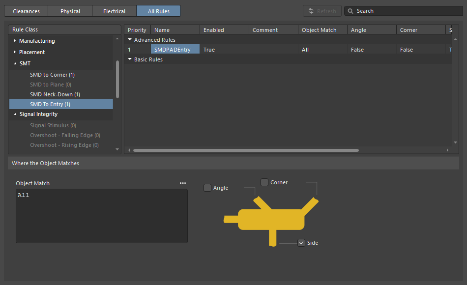
| SMD Entry | 이 제약은 라우트가 패드에 진입할 수 있는 위치를 정의합니다. 이 제약에서 패드의 Side는 더 긴 가장자리입니다. |
Pad Entry Stability
Pad Entry Stability 슬라이더는 중앙에 정렬된 pad entry를 보호합니다. 글로싱 중에 이미 중앙에 정렬된 pad entry(exit)를 보호하는 데 적용되며, 기존의 중심에서 벗어난 pad entry를 다시 중앙으로 맞추려고 하지는 않습니다.
-
0 (Off) =보호 없음 -
10 (Max) =최대 보호
Pad Entry Stability 기능을 사용해 라우트가 패드 중앙에 유지되도록 도와주십시오.
Center Routes Between Pads
대화형 라우팅 엔진은 설계 제약을 준수합니다. 즉, 부품 패드와 비아 사이를 라우팅할 때 적용 가능한 clearance 제약에 지정된 최소 이격으로 트랙 세그먼트를 배치합니다. 보드 설계자들이 흔히 원하는 것은 가능한 경우 패드와 비아 사이에서 라우트를 중앙에 배치하여, 패드 또는 비아에 있는 net과 현재 라우팅 중인 net 사이의 분리를 최대화하는 것입니다.
Apply Trace Centering 옵션이 이를 수행합니다. 센터링 알고리즘이 유연하게 동작하고 두 패드 사이, 두 비아 사이, 또는 패드와 비아 사이 어디에나 적용될 수 있도록, 원하는 센터링 거리는 적용 가능한 clearance 제약의 배수로 지정되며, 여기서:
Distance = Clearance + Added Clearance Ratio x Clearance
대화형 라우팅 엔진은 대상 패드/비아 주위로 이 Distance로 라우팅하려고 시도하며, 트레이스의 다른 쪽 가장자리에서 가장 가까운 패드 또는 비아까지의 거리가 Distance보다 작아지면 이를 자동으로 줄이고(그리고 중앙 정렬합니다).
가능한 경우, 현재 라우팅되거나 드래그 중인 net과 기존 패드/비아 사이에 추가 clearance를 더합니다.
Pad Entry Stability |
|
| Apply trace centering | Apply Trace Centering 옵션이 활성화되면, 대화형 라우팅과 대화형 슬라이딩 중에 trace centering이 적용됩니다. 라우팅 엔진이 라우트가 패드/비아 사이를 통과하고 있음을 감지하면, 적용 가능한 clearance 제약에 적용 가능한 clearance 제약과 Added Clearance Ratio를 곱한 값을 더한 최대 거리까지 라우트를 중앙에 배치하려고 시도합니다. 대화형 슬라이딩 중 센터링을 비활성화하려면 Disable Trace Centering When Dragging option을 사용하십시오. |
| Center between what? | trace centering 기능은 패드가 동일한 부품에 속할 필요가 없으며, 임의의 두 패드, 임의의 두 비아, 또는 임의의 패드와 임의의 비아 사이에서 중앙 정렬할 수 있습니다. 비아-비아 또는 비아-패드 조합 사이의 센터링을 활성화/비활성화하려면 Adjust Vias option 을 사용하십시오. |
| Where is the center? | 관련 패드/비아 사이의 중심을 식별하려고 하기보다, 이 기능은 적용 가능한 clearance의 배수를 사용하며, 그 값이 clearance에 추가됩니다. 예를 들어 적용 가능한 clearance가 0.15 mm인 경우, 옵션을 2로 설정하면 라우팅 엔진은 가능한 경우 기존 패드와 비아로부터 0.15 + 2*0.15 = 0.45 mm만큼 이격하도록 지시받습니다. 이후 필요하면 라우팅 엔진은 이 clearance를 지정된 clearance까지 줄일 수 있습니다. |
Auto-Shrinking during Routing
최신 부품 기술에서의 과제 중 하나는 보드를 가로질러 이동하는 동안 하나의 넷을 서로 다른 폭으로 라우팅해야 한다는 점입니다. 국부적인 수준에서는 부품 핀 사이를 통과할 때 라우팅 폭을 줄여야 할 수 있습니다. 보드 수준에서는 BGA 부품 아래 볼 사이를 통과하는 모든 라우트를 더 좁게 해야 할 수 있습니다. 인터랙티브 라우팅은 이러한 요구를 여러 방식으로 지원합니다.
국부적 자동 축소
인터랙티브 라우팅 중 흔히 겪는 문제는 라우트가 부품 패드에 접근했지만 그 사이를 통과할 만큼 충분히 맞지 않는 경우입니다. 설계자는 라우트를 대화형으로 좁히고(설계 제약 조건에서 허용하는 크기 범위 내에서), 더 좁은 트레이스를 핀 사이로 통과시킨 다음, 다시 폭을 넓혀 해당 넷의 라우팅을 계속할 수 있습니다. 이 과정을 수동으로 제어하는 대신 Auto Shrinking 기능을 활성화할 수 있습니다.
영역 기반 자동 축소
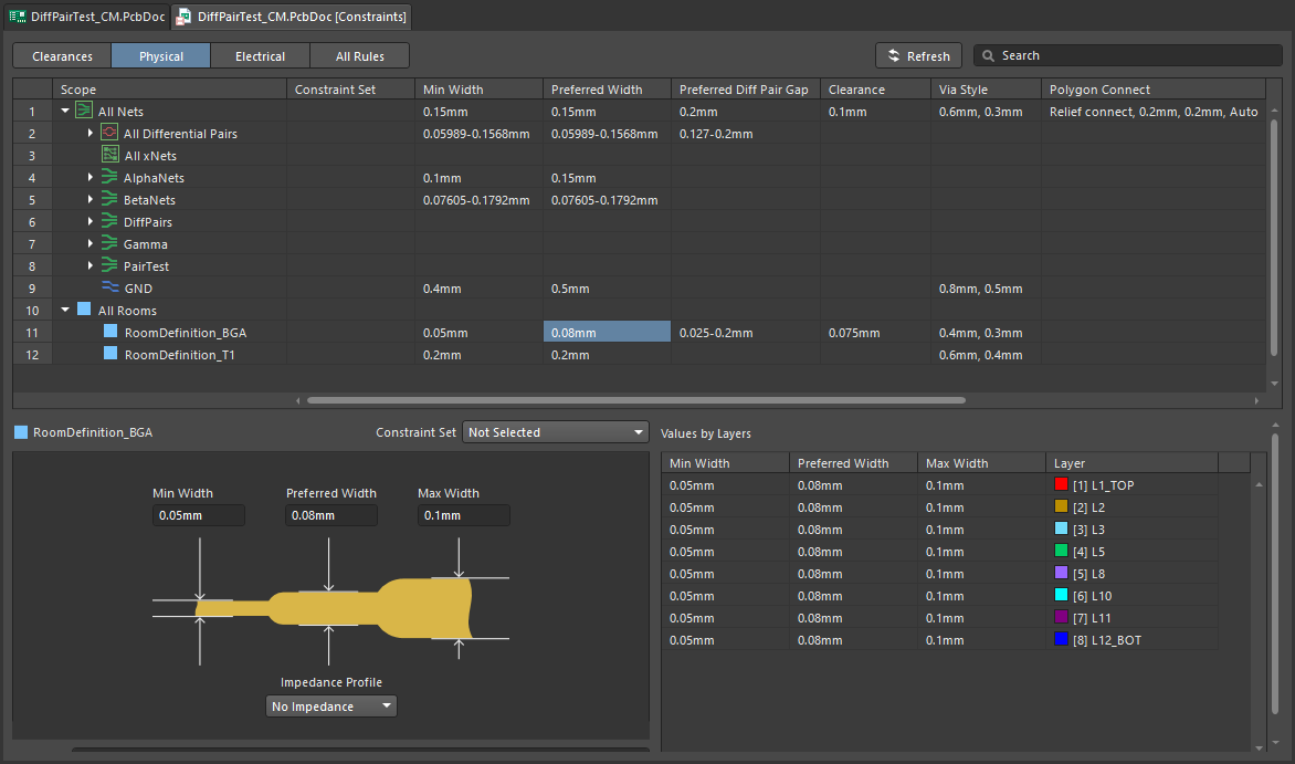
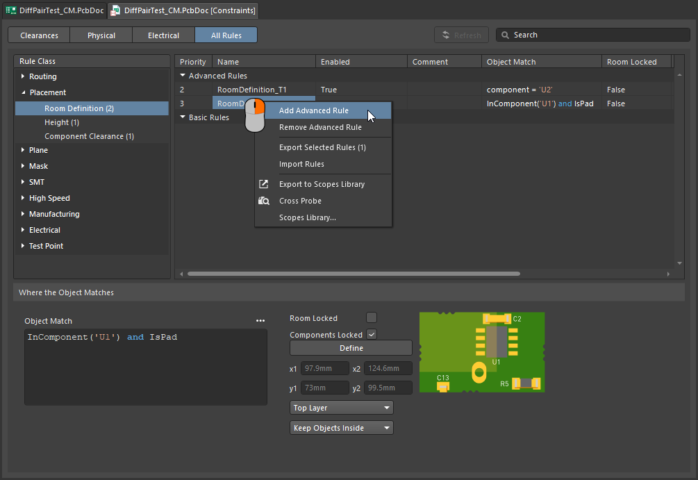
BGA 부품은 작고 서로 매우 가까이 배치된 패드 배열을 사용합니다. 이 때문에 라우팅이 까다로우며, 내부 패드 행까지 라우팅하려면 라우팅 폭을 줄여야 하는 경우가 많습니다. 이 작업은 이 페이지에 설명된 기법을 사용하여 인터랙티브 라우팅 중 수동으로 수행할 수 있습니다. 또한 배치 룸과 룸 기반 라우팅 폭 제약 조건을 추가하여 이러한 폭 전환 동작을 자동화할 수도 있습니다. 인터랙티브 라우터는 이러한 제약 조건을 따르므로, 룸에 들어가거나 나갈 때 트랙이 자동으로 좁아졌다가 다시 넓어집니다.
룸 내부에서는 라우팅 폭과 클리어런스가 자동으로 조정됩니다.
영역 내부에서 라우팅 축소하기 |
|
| Define the area | 라우트 폭을 줄여야 하는 영역은 placement room constraint ( |
| Define the width | 라우팅 폭은 적용 가능한 Routing Width Constraint ( |
 )
)defining constraints within a room에 대해 자세히 알아보십시오.
Follow mode – Tracing an Existing Shape
어려운 요구 사항 중 하나는 기존 형상이나 윤곽을 따라가도록 라우트를 배치하는 것입니다. 그 윤곽은 장애물, 컷아웃, 보드 외곽선 또는 기존 라우트일 수 있습니다.
새 라우트가 윤곽을 밀착해서 따라가도록 세심하고 정확한 마우스 움직임과 클릭 동작으로 윤곽을 따라 라우팅해야 하는 대신, Follow 모드에서는 따라갈 윤곽을 클릭해 지정한 다음 커서를 움직여 라우트 방향을 정의하면 됩니다. 인터랙티브 라우터는 적용 가능한 설계 규칙을 준수하면서 새 라우트가 해당 윤곽을 따라가도록 트랙 및 아크 세그먼트를 추가합니다. 이 기능은 특히 곡선 라우트를 배치할 때 유용합니다.
Follow 모드를 사용하면 기존 형상을 정확히 따라 라우팅할 수 있습니다.
윤곽을 따라 라우팅하기 |
|
| 첫 번째 단계 | 일반적인 방법으로 Interactive Routing 명령을 실행하고 라우팅할 넷을 클릭합니다. |
| Follow 모드 활성화 | 라우트가 시작된 상태에서 위 비디오에서는 첫 번째 라우트에 대해 보드 컷아웃을 따르고, 그다음 다른 각 라우트에 대해서는 이전 라우트를 따릅니다. |
| To place the follow route | 다음 마우스 왼쪽 클릭은 따라가는 라우트의 종료 지점으로 해석되며, 클릭 후에는 일반 인터랙티브 라우팅으로 돌아갑니다. |
| To abort Follow mode | Backspace을 눌러 Follow 모드에서 빠져나와 일반 인터랙티브 라우팅으로 돌아갑니다. 또는 Esc을 눌러 Follow 모드를 취소하고 이 연결의 라우팅도 함께 중단할 수 있습니다. |
| Differential pairs | Follow 모드는 차동쌍도 지원합니다(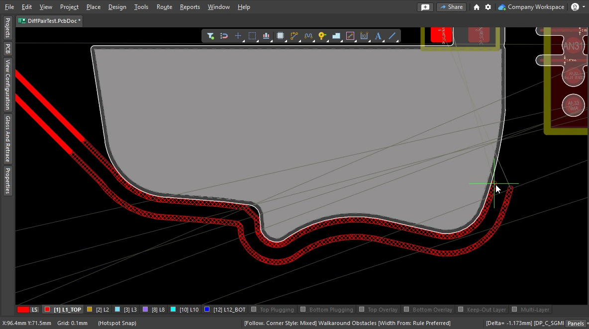 ). ). |
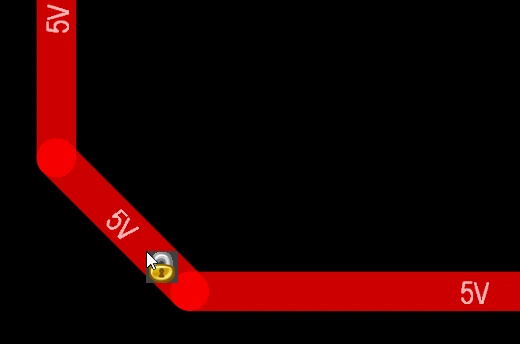
Intentionally shorting different nets
서로 다른 두 넷을 의도적으로 연결해야 하는 경우는 드물지 않습니다. 예를 들어 아날로그 그라운드와 디지털 그라운드를 제어된 방식으로 연결해야 할 수 있습니다. 이는 두 넷을 Net Tie 부품을 통해 연결함으로써 구현됩니다. Net Tie 부품은 제어된 단락 회로에 불과하며, 이를 통해 보드 상에서 넷들이 연결되는 위치를 결정할 수 있습니다.
Net Tie 패드 쪽으로 라우팅할 때의 문제는 규칙 엔진이 위반이 곧 발생할 것으로 판단하고 Net Tie 패드까지 라우팅하지 못하게 한다는 점입니다. 하지만 Net Tie 패드에서 라우팅을 시작하면 이런 문제는 발생하지 않습니다. 또는 Routing Mode을(를) 일시적으로 Ignore Obstacle(으)로 전환할 수도 있습니다.
Net Tie를 라우팅하려면 Net Tie 패드에서 바깥쪽으로 라우팅하십시오.
Intentionally Connecting Two Nets에 대해 자세히 알아보십시오.
Fanout and Escape Routes
Altium Designer에는 표면실장 부품 팬아웃 도구가 포함되어 있으며, BGA 이스케이프 라우팅도 지원합니다. 이스케이프 라우팅 엔진은 각 패드를 디바이스 가장자리 바로 바깥까지 라우팅하려고 시도하므로, 이들에 대한 라우팅 연결이 훨씬 쉬워집니다. Fanout은 인터랙티브 라우팅 또는 자동 라우팅 전에 실행하도록 설계되었으며, 라우팅되지 않은 부품에 대해서만 팬아웃을 시도합니다.
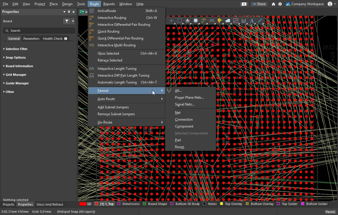
Fanout 및 이스케이프 라우팅은 메인 메뉴의 Route » Fanout 하위 메뉴에서 실행하거나, 부품의 오른쪽 클릭 메뉴에서 Component Actions » Fanout Component 명령을 사용하여 실행합니다.
Fanout 옵션 설정
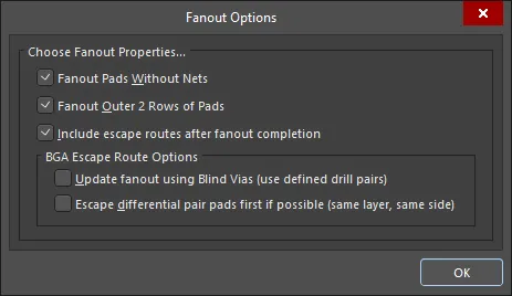
팬아웃 명령 중 하나를 선택하면 Fanout Options 대화상자가 열립니다. 이 대화상자에는 팬아웃 및 이스케이프 라우팅 옵션과 블라인드 비아 사용 옵션을 지정할 수 있는 컨트롤이 포함되어 있습니다. 블라인드 비아 옵션은 Via Types tab of the Layer Stack Manager에 적절한 블라인드 Via Type이 정의되어 있는 경우에만 사용할 수 있습니다.
 팬아웃된 BGA입니다. 패드는 솔리드로 표시되고 팬아웃 트랙과 비아는 반투명으로 표시됩니다. 팬아웃은 대화상자의 설정을 기준으로, Fanout Control 제약 조건에 따라 수행됩니다.
Fanout 옵션 ( |
|
| Fanout Pads Without Nets | 이 옵션을 활성화하면 부품의 패드에 넷이 할당되어 있지 않더라도 팬아웃합니다. 이 옵션이 비활성화되면 넷이 할당된 패드만 팬아웃됩니다. |
| Fanout Outer 2 Rows of Pads | 이 옵션을 활성화하면 바깥쪽 두 개 행의 패드도 팬아웃합니다(일반적으로 이들은 라우팅이 쉬움). |
| Include escape routes after fanout completion | 이 옵션을 활성화하면 각 팬아웃에 이스케이프 라우팅도 추가됩니다. 이스케이프 라우팅은 팬아웃 비아와 부품 패드에 트랙을 배치하여 이를 부품 가장자리까지 끌어냅니다. |
| Update fanout using Blind Vias (BGA escape routing only) | 이 옵션을 활성화하면 레이어 스택에서 구성된 드릴 페어 레이어 사이에 블라인드 비아를 배치합니다. 이 옵션이 비활성화되면 드릴 페어 레이어 설정과 관계없이 스루홀 비아만 배치됩니다. 블라인드 비아를 사용할 수 있는 드릴 레이어 페어가 정의되어 있지 않으면 이 옵션은 Cannot Fanout using Blind Vias (no layer pairs defined)(으)로 표시됩니다. |
| Escape differential pair pads first if possible (same layer, same side) | 이 옵션을 활성화하면 할당된 모든 차동쌍 넷을 다른 팬아웃 작업보다 먼저 함께 팬아웃 및 이스케이프 라우팅하여, 결과적으로 해당 라우트를 함께 유지합니다. 팬아웃은 동일한 레이어에, 가능한 한 서로 인접하게 이스케이프 라우팅 트랙을 배치합니다. |
 )
)Fanout 동작
사용된 내부 패드는 먼저 전통적인 도그본(dog-bone) 방식(끝에 비아가 있는 짧은 라우트)으로 팬아웃되어 다른 레이어에 접근한 다음, 그 비아로부터 디바이스 가장자리를 약간 벗어난 지점까지 이스케이프 라우팅됩니다. 이 과정은 사용 가능한 라우팅 레이어를 따라 모든 패드가 이스케이프 라우팅될 때까지 진행됩니다. 이스케이프 라우팅할 수 없었던 모든 패드에 대한 보고서가 생성되어 열리며, 보고서의 항목을 클릭하면 PCB에서 해당 객체로 크로스 프로빙하여 확인할 수 있습니다.
 1mm 피치 BGA의 팬아웃 및 이스케이프 라우트 예시.
팬아웃 수행 |
|
| Running a fanout | Route » Fanout 하위 메뉴에서 필요한 팬아웃 명령을 선택합니다. 어떤 메뉴 명령을 선택하든 Fanout Options 대화상자가 열립니다. 설정을 완료하고 OK를 클릭하면 선택한 팬아웃이 수행됩니다. |
| What controls the fanout process? | Fanout Options 대화상자의 설정뿐 아니라, 팬아웃 및 이스케이프 라우팅은 Fanout Control, Routing Width, Routing Via Style (팬아웃 비아용), Routing Layers, Electrical Clearance 제약을 포함한 해당 설계 제약에 따라 수행됩니다. |
| Why does nothing happen when I run a fanout command? | 이 문제는 다음과 같은 이유로 발생할 수 있습니다.
|
| Why do some of the fanouts show violations as soon as they have been placed? |
|
팬아웃 명령
모든 팬아웃 명령은 Route » Fanout 하위 메뉴에서 사용할 수 있습니다. 커서 아래에 있는 컴포넌트에 대해서도 팬아웃할 수 있으며, 컴포넌트를 마우스 오른쪽 버튼으로 클릭한 후 컨텍스트 메뉴에서 Fanout Component을(를) 선택하면 됩니다.
 )
)Interactive Multi-Routing
PCB에서는 Address 및 Data 버스처럼 여러 신호를 동일한 경로를 따라 함께 라우팅해야 하는 경우가 자주 있습니다. 이를 지원하기 위해 대화형 라우터에는 interactive multi-routing 명령이 포함되어 있습니다. 멀티 라우트 프로세스는 멀티 라우팅 Properties 패널(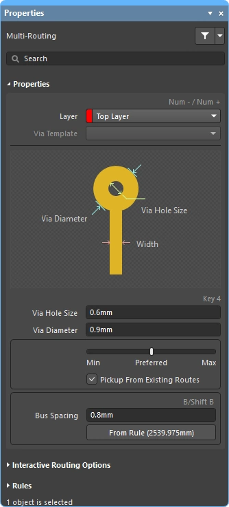 )에서 구성하며, 단축키로도 제어할 수 있습니다.
선택된 여러 넷을 동시에 멀티 라우팅할 수 있습니다.
대화형 멀티 라우팅 중에는 Tab을 눌러 Properties 패널을 열고 설정을 구성합니다.
멀티 라우트 수행
| Choose the connections to route | 명령을 실행하기 전에, 라우팅에 포함할 각 넷의 소스 패드를 선택합니다. Shift+click 로 개별 패드를 선택하고, Ctrl+click and drag 로 선택 사각형을 그려 컴포넌트 내 여러 하위 패드를 부분 선택합니다. |
| Start multi-routing | Interactive Multi-Routing 명령은 Route 메뉴 또는 Active Bar (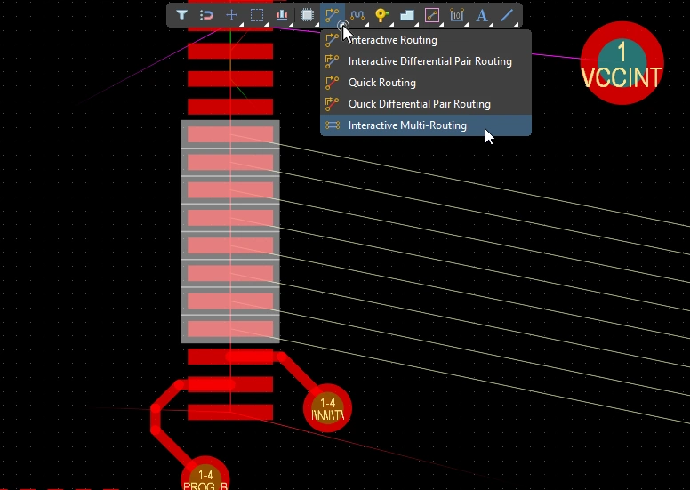 )에서 실행할 수 있습니다. 명령을 실행하면 멀티 라우팅을 시작할 위치를 클릭하라는 메시지가 표시됩니다. 첫 번째 트랙 세그먼트 세트를 배치하려는 설계 공간의 지점을 클릭한 다음, 목표 지점을 향해 필요에 따라 계속 라우팅하면 됩니다. )에서 실행할 수 있습니다. 명령을 실행하면 멀티 라우팅을 시작할 위치를 클릭하라는 메시지가 표시됩니다. 첫 번째 트랙 세그먼트 세트를 배치하려는 설계 공간의 지점을 클릭한 다음, 목표 지점을 향해 필요에 따라 계속 라우팅하면 됩니다. |
| Controlling the track spacing | B 단축키를 사용하면 버스 간격을 줄일 수 있고, (Shift+B) 단축키를 사용하면 현재 스냅 그리드 단위로 버스 간격을 늘릴 수 있습니다. C 을 누르면 버스 간격이 해당 Routing Width 설계 제약에서 허용하는 최소값으로 수렴됩니다. |
| Changing the route properties | Interactive Routing과 동일한 단축키를 사용하여 충돌 해결 모드를 순환하거나, 라우팅 레이어를 전환하거나, 비아 옵션을 변경하는 등의 다른 작업도 수행할 수 있습니다. |
멀티 라우팅 속성 ()
| Layer | 멀티 라우트가 배치되는 레이어입니다. 드롭다운을 사용하여 다른 레이어를 선택하면 비아가 자동으로 추가됩니다. 또는 레이어 변경 단축키를 사용할 수도 있습니다. |
| Via Template | 비아가 템플릿과 연관되어 있는 경우 여기에 템플릿 이름이 표시되며 드롭다운을 사용해 변경할 수 있습니다. 패드 및 비아 템플릿에 대해 자세히 알아보십시오. |
| Via Hole Size | 사용될 비아 홀 크기를 표시합니다. 이 값은 해당 routing via style 설계 제약이 허용하는 범위 내에서 직접 편집할 수 있습니다. |
| Via Diameter | 사용될 비아 직경을 표시합니다. 이 값은 해당 routing via style 설계 제약이 허용하는 범위 내에서 직접 편집할 수 있습니다. |
| Routing width selector | 슬라이더를 사용해 해당 routing width constraint에 정의된 Min/Preferred/Max 값으로 라우팅 폭을 설정합니다. |
| Pickup From Existing Routes | 이 옵션을 활성화한 상태에서 기존 트랙에서 라우팅을 시작하면 기존 트랙 폭이 사용되며(슬라이딩 선택기에서 선택한 폭보다 우선 적용됨). |
| Bus Spacing | 원하는 버스 간격을 입력하거나, 멀티 라우팅 중 간격을 대화형으로 늘리거나 줄이기 위해 |
| From Rule | 버튼을 클릭하거나(또는 C 단축키 사용) 버스 간격을 해당 Electrical Clearance 제약에서 정의된 거리로 변경할 수 있습니다. |
대화형 라우팅 옵션
멀티 라우팅 설계 제약 (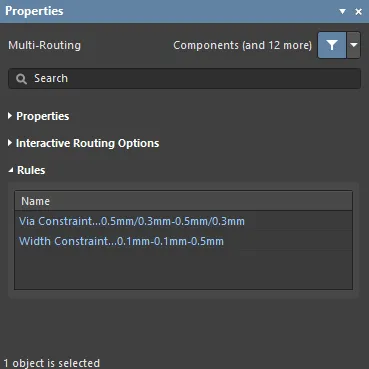 )
)
적용 가능한 라우팅 및 비아 제약은 Rules 패널의 Properties 섹션 아래에 표시됩니다.
Subnet Jumpers
FPGA 기반 설계의 큰 강점 중 하나는 라우팅 문제를 PCB와 FPGA 양쪽에서 모두 해결할 수 있다는 점이며, 이를 통해 라우팅 레이어 수를 줄이고 PCB를 더 단순하게 만들 수 있다는 것입니다. 이것이 현실이 되려면 설계 시스템이 PCB 주도 핀 스왑과 FPGA 주도 핀 스왑을 모두 지원해야 합니다. Altium Designer는 PCB 편집기에서 단순한 2핀 부품부터 고핀 수 FPGA까지 핀 스왑을 지원합니다.
라우팅된 PCB를 포함해 설계 프로세스의 어느 단계에서나 핀 스왑을 지원하기 위해, PCB 편집기에서는 subnet jumpers라고 하는 작은 라우팅 연결자를 추가하거나 제거할 수 있습니다. 서브넷 점퍼는 소프트웨어가 쉽게 배치하고 제거할 수 있는 요소로 인식하는 짧은 트랙 세그먼트입니다. 이는 Add 및 Remove Subnet Jumper 명령을 Route 메뉴에서 수동으로 실행해서 처리할 수도 있고, 대화형 라우팅 중 스왑 가능한 핀으로 라우팅할 경우 라우팅 엔진이 자동으로 처리할 수도 있습니다.


 ).
).대화형 라우팅 중 대상이 동일 넷 라우트가 아니라 스왑 가능한 라우트인 경우, 서브넷 점퍼가 자동으로 추가됩니다.
 ).
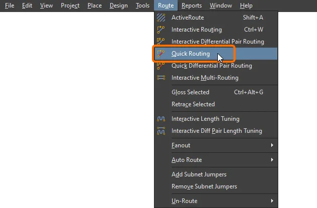
).Quick Routing Tools
설계 요구사항이 비교적 낮은 디자이너를 위해 quick routing 명령 쌍도 제공됩니다. Quick Routing 도구는 직관적인 방식으로 라우팅 효율성과 유연성을 극대화하도록 도와주며, 라우트 구간 배치를 위한 커서 경로 추종, 클릭 한 번으로 라우팅 완료, 장애물 밀어내기 또는 우회, 기존 연결 자동 추종 등의 기능을 모두 해당 설계 규칙에 맞게 제공합니다.
메인 메뉴와 Active Bar에서 접근할 수 있는 Quick Routing 명령은 설정과 기능이 더 적은 가벼운 라우팅을 제공하며, 더 단순한 설계에 적합합니다. 일반적인 동작과 단축키는 표준 Interactive Routing 명령과 동일합니다.
기능 요약 |
|
| Includes | 포함된 기능은 다음과 같습니다:
|
| Does not support | 이 라우터는 Quick 라고 불리며, 이는 제공 기능 세트가 축소되어 있기 때문입니다. Quick Router에 포함되지 않는 기능은 다음과 같습니다:
이러한 기능이 필요하다면 Interactive Routing 도구를 사용하십시오. |
넷 정보 (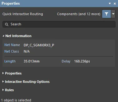 )
)
대화형 라우팅 및 대화형 슬라이딩 중에는 편집 중인 넷의 정보가 Properties 패널의 Net Information 섹션에 표시됩니다.
Quick Routing 속성 (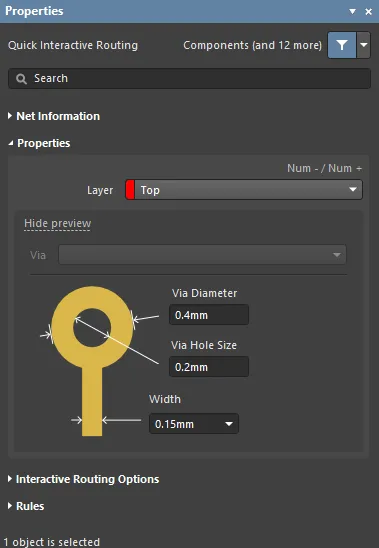 )
)
Quick 대화형/차동 페어 라우팅 중에는 라우트 객체의 속성을 Properties 패널의 Routing Properties 섹션에서 편집할 수 있습니다.
대화형 라우팅 옵션 (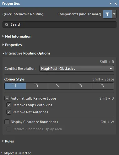 )
)
사용 가능한 대화형 라우팅 옵션은 Properties 패널의 Interactive Routing Options 섹션 아래에 나열됩니다.
설계 제약 (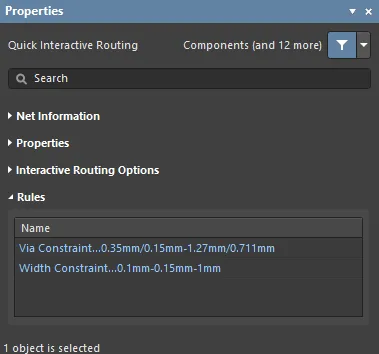 )
)
적용 가능한 라우팅 및 비아 제약은 Properties 패널의 Rules 섹션 아래에 나열됩니다.
라우팅 업데이트
라우팅은 대화형 프로세스이므로, 디자이너는 보드 설계를 완료하는 동안 기존 라우팅을 지속적으로 조정, 업데이트 또는 제거해야 합니다.
라우팅을 변경하는 가장 간단한 방법은 해당 라우트를 클릭한 채로 새 위치로 드래그하는 것입니다. 그러나 때로는 슬라이딩이 해결책이 아니며, 대신 특정 구간을 재라우팅해야 할 수도 있습니다. 대화형 라우팅 엔진은 Loop Removal라는 기능을 통해 이를 지원합니다. 이 기능은 대화형 라우팅 과정을 모니터링하다가, 기존 경로와 나란히 새로운 경로가 라우팅되었다고 감지하면 오래된 중복 세그먼트를 자동으로 제거합니다.
기존 라우트를 드래그하는 작업을 Interactive Sliding이라고 하며, 이에 대한 제어는 슬라이딩 중 Properties 패널에 표시됩니다 ( ). 슬라이딩 중 대화형 라우팅 엔진은 적용 가능한 설계 제약을 준수하면서 라우팅 품질을 유지하려고 시도합니다. 슬라이딩 프로세스를 제어하는 주요 기능에는 라우팅 충돌 해결 모드(장애물에 대한 대응), 글로스 강도(결과를 정리하는 정도), 허깅(장애물을 감싸며 코너를 형성하는 방식)이 포함됩니다. T-정션 및 버텍스 드래깅, 비아 드래깅, 차동 페어 드래깅 지원 등 대화형 슬라이딩을 지원하는 다양한 기능도 제공됩니다.
라우팅된 부품의 드래깅을 지원하는 기능도 있습니다.
Strategies for Selecting the Routing
대화형 소프트웨어 도구의 큰 과제 중 하나는 이러한 도구를 디자이너의 손끝과 자연스럽게 연결하여, 라우팅 생성, 재형성, 정리와 같은 다양한 작업 사이를 쉽고 유연하게 오갈 수 있도록 하는 것입니다. 이를 위해서는 관심 있는 라우트를 쉽게 선택할 수 있어야 합니다.
라우트를 선택하는 가장 쉬운 방법은 관심 있는 넷의 아무 객체나 한 번 클릭한 다음, 아래 비디오에 나온 것처럼 Tab 키를 누르는 것입니다.
Tab 단축키를 사용한 라우트 선택 기법 시연.
Tab를 누르면:
-
첫 번째 누름 – 같은 레이어에 있는 동일 connected의 모든 라우팅 객체 선택
-
두 번째 누름 – 연결된 모든 라우팅 객체 선택 all layers
-
세 번째 누름 – 설계 공간의 all objects on that net 선택(연결되지 않은 넷 객체가 없으면 건너뜀)
-
네 번째 누름 – 초기 선택 집합으로 복귀
라우트 선택 기법 |
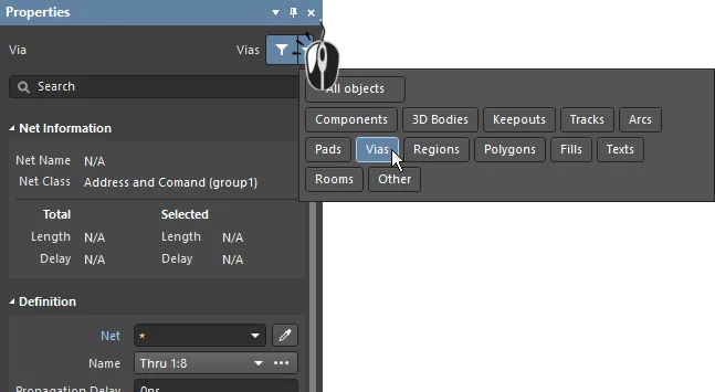
|
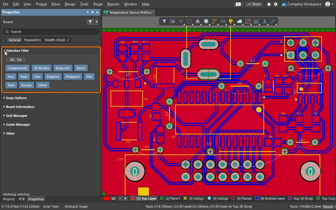
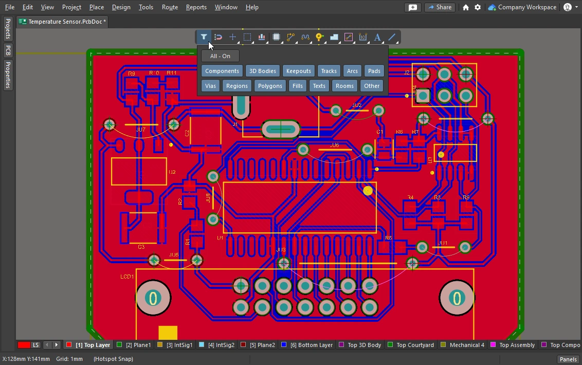
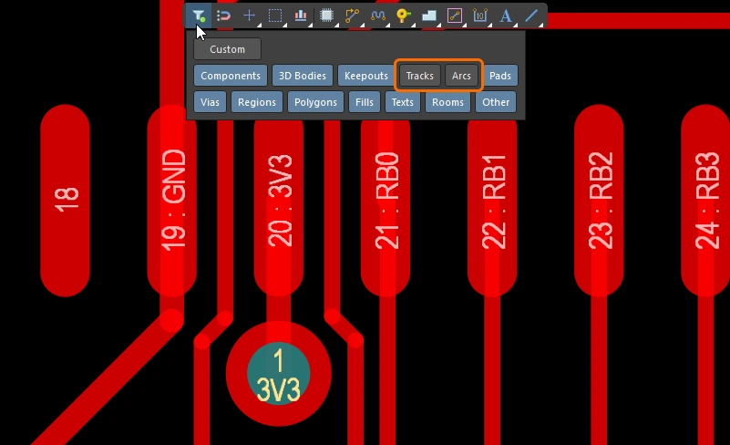
| What can be selected? | Altium Designer의 모든 그래픽 편집기에는 selection filter이 포함되어 있습니다. 이 필터는 현재 선택 가능한 객체 유형을 정의하며, Properties 패널( selection filter 사용 및 active bar에 대해 자세히 알아보세요. |
| Left Mouse Click | 커서 아래의 객체를 선택하려면 클릭합니다. 커서 아래에 여러 객체가 있으면 우선순위 순서에 따라 하나만 선택됩니다. 마우스를 움직이지 않으면, 이후 마우스를 클릭할 때마다 우선순위에 따라 스택의 다음 객체가 선택됩니다. |
| Selection rectangle – everything touched | 빈 공간에서 클릭한 뒤 왼쪽으로 드래그하면 녹색 선택 사각형이 만들어집니다( ). 녹색 사각형에 닿는 모든 객체가 선택됩니다( ). 녹색 사각형에 닿는 모든 객체가 선택됩니다( ) (selection filter에서 허용된 경우). ) (selection filter에서 허용된 경우). |
| Selection rectangle – objects within | 빈 공간에서 클릭한 뒤 오른쪽으로 드래그하면 파란색 선택 사각형이 만들어집니다( ). 파란색 사각형 안에 완전히 포함된 객체만 선택됩니다( ). 파란색 사각형 안에 완전히 포함된 객체만 선택됩니다( ) (selection filter에서 허용된 경우). ) (selection filter에서 허용된 경우). |
| Select a connection line | Alt+Left click and drag left ( ). 녹색 선택 사각형에 닿는 모든 표시된 연결선이 선택됩니다. ). 녹색 선택 사각형에 닿는 모든 표시된 연결선이 선택됩니다. |
| Select existing routes | Left click and drag left ( ). 녹색 선택 사각형에 닿는 잠금 해제된 모든 트랙 세그먼트가 선택됩니다. 해당 넷의 추가 트랙 세그먼트를 선택하려면 Tab 키를 사용합니다. ). 녹색 선택 사각형에 닿는 잠금 해제된 모든 트랙 세그먼트가 선택됩니다. 해당 넷의 추가 트랙 세그먼트를 선택하려면 Tab 키를 사용합니다. |
| Select routes under a component |
|
| Select component pads | Ctrl+Left click and drag left ( ). 녹색 선택 사각형에 닿는 잠금 해제된 모든 컴포넌트 패드가 선택됩니다. ). 녹색 선택 사각형에 닿는 잠금 해제된 모든 컴포넌트 패드가 선택됩니다. |
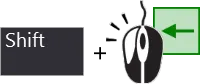
| Adding to the selection | Shift를 누르고 있으면 현재 선택을 유지한 상태에서 추가 객체를 선택할 수 있습니다. |
| Selecting from the PCB panel | 선택하려는 객체는 알고 있지만 위치를 모를 경우, PCB 패널을 사용해 넷, 차동 페어, 컴포넌트 등을 찾아 선택할 수 있습니다. 이 패널에서는 선택만 할 수 있는 것이 아니라, 객체로 확대하고 다른 모든 객체를 페이드(마스크 또는 디밍) 처리하도록 설정할 수도 있습니다( PCB panel에 대해 자세히 알아보세요. |
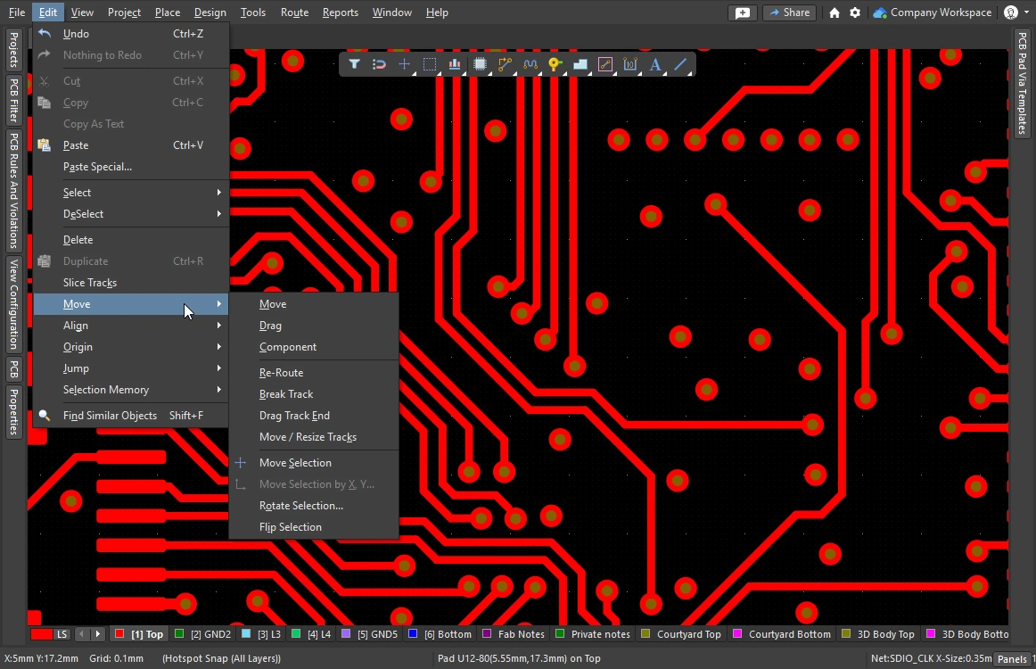
| Accessing all of the selection commands | Edit » Select 메뉴를 선택하면 PCB 편집기의 모든 선택 명령에 접근할 수 있습니다( 예를 들어 |
 )
) )
) ).
). ).
). ).
).이 섹션에서는 라우팅 선택 기법을 요약합니다. PCB editor object selection commands에 대해 자세히 알아보세요.
Cleaning and Clearing the Routes
전체 넷의 라우팅을 제거하려면 해당 넷을 선택한 후 Delete를 누르면 됩니다. 그러면 연결성 엔진이 연결선을 자동으로 복원합니다. 또한 라우팅의 일부 구간만 선택적으로 제거해야 할 때도 있습니다. 예를 들어 단일 물리적 연결을 언라우팅하거나, 라우트를 따라 특정 지점까지 여러 트랙 세그먼트를 제거해야 할 수 있습니다.

Backspace 키를 사용하면 세그먼트를 제거하고 마지막으로 접촉한 세그먼트를 선택할 수 있습니다.
 )
) )
)루프 재라우팅 및 제거
라우팅 중에는 기존 라우트의 경로를 변경해야 하는 경우가 있습니다. 경로 변경이 복잡하다면 기존 라우팅을 슬라이드하는 것보다 새 경로를 라우팅하는 편이 더 효율적일 수 있습니다. 이는 Automatic Loop Removal 기능으로 지원됩니다.
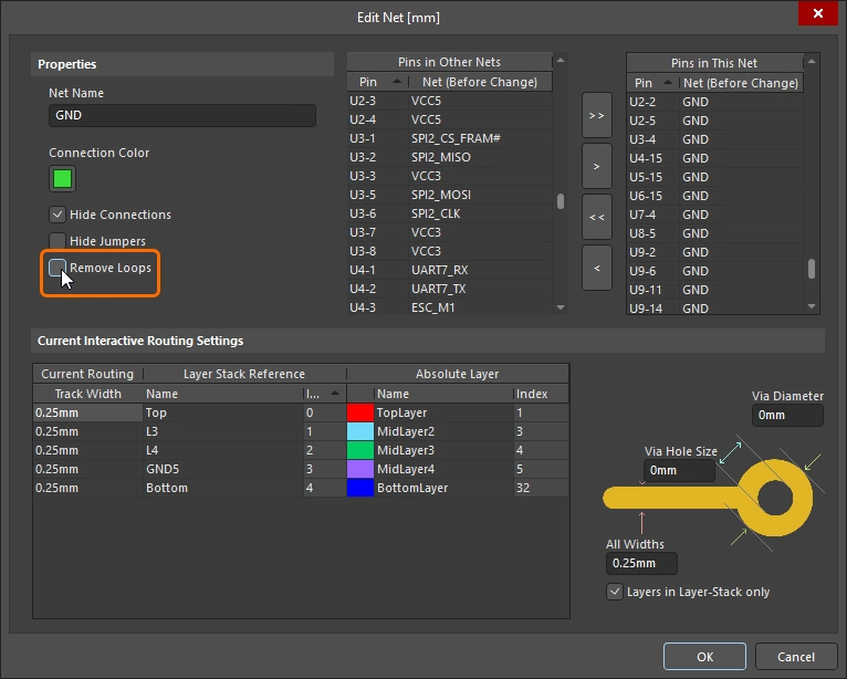
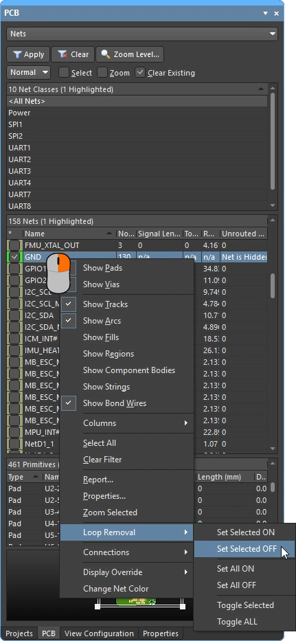
이 기능은 인터랙티브 라우팅 과정을 모니터링하며, 기존 경로와 나란한 새 경로가 라우팅되었다고 감지되면 이전의 불필요한 세그먼트를 자동으로 제거합니다. 이 옵션은 기본적으로 활성화되어 있으며( ), 모든 넷에 적용됩니다. 선택한 넷에 대해서는 비활성화할 수 있고, 특정 루프를 만들기 위해 인터랙티브 라우팅 중 일시적으로 비활성화할 수도 있습니다. 이 넷에 대해 루프 제거를 다시 활성화해도 방금 만든 루프는 유지됩니다.
Automatic Loop Removal이 활성화된 상태에서는 새 라우트 경로가 기존 라우트와 다시 만나면 기존 루프가 자동으로 제거됩니다.
 )
) )
) )
) )
)

라우팅 이동
기존 라우트를 드래그하는 작업을 interactive sliding. 라고 합니다. 인터랙티브 슬라이딩 제어는 Preferences 대화상자( )에서 사용할 수 있으며, 슬라이딩 중
 Tab를 눌러 Properties 패널()에서도 접근할 수 있습니다. 슬라이딩 중 인터랙티브 라우팅 엔진은 적용 가능한 설계 제약을 준수하면서 라우팅 품질을 유지하려고 시도합니다.
슬라이딩 과정을 제어하는 주요 기능에는 라우팅 충돌 해결 모드(장애물에 대한 반응), gloss 강도(결과를 정리하는 정도), hugging(장애물을 감싸고 코너를 형성하는 방식)이 포함됩니다. 인터랙티브 슬라이딩을 지원하는 기능으로는 T-접합 및 버텍스 드래깅, 비아 드래깅, 차동 페어 드래깅 지원 등이 있습니다.
기존 라우팅을 수정하는 데 사용되는 인터랙티브 슬라이딩의 예시입니다.
인터랙티브 슬라이딩(드래깅) |
|
| To slide (drag) a track | 트랙 세그먼트를 클릭한 상태로 유지한 뒤 마우스를 움직여 라우트 슬라이딩을 시작합니다. PCB 에디터는 연결된 세그먼트와의 45/90도 각도를 자동으로 유지하면서 필요에 따라 이를 줄이거나 늘립니다. 인터랙티브 슬라이딩은 비직교 라우팅도 지원합니다. 라우트가 움직이지 않는다면, 라우트가 잠겨 있을 수 있습니다(이를 나타내는 아이콘이 표시됨 |
| To change the sliding behavior | 슬라이딩 중 Tab를 눌러 Properties 패널을 열면, 인터랙티브 슬라이딩 설정()을 변경할 수 있습니다. 이러한 설정은 슬라이드 중인 트랙뿐 아니라 슬라이딩 중 밀려나는 인접 트랙도 제어합니다. 보드에 사용된 라우팅 스타일에 맞게 슬라이딩 옵션을 구성하십시오. 예를 들어 라우팅에 대각선 코너가 있다면 Hugging Style는 45 Degree이어야 합니다. 슬라이딩 중 Shift+Spacebar 단축키를 눌러 Hugging Style 모드를 순환할 수 있습니다. |
| How the sliding routes are impacted | 슬라이딩하면서 움직이는 트랙이 어느 정도까지 재형성되는지는 현재 Gloss Effort (Routed) 설정( |
How the sliding route responds to existing objects |
슬라이딩 중에는 Routing Conflict Resolution 모드 중 하나(Ignore, Push, HugNPush)가 적용됩니다( ). 트랙 세그먼트를 드래그하는 동안 Shift+R를 눌러 모드를 순환할 수 있습니다. ). 트랙 세그먼트를 드래그하는 동안 Shift+R를 눌러 모드를 순환할 수 있습니다. |
| How neighboring routes are impacted | 움직이는 트랙이 인접 라우팅에 미치는 영향은 현재 Gloss Effort (Neighbor) 설정( )에 의해 제어되며, 슬라이딩 중 Tab를 눌러 설정을 변경할 수 있습니다. )에 의해 제어되며, 슬라이딩 중 Tab를 눌러 설정을 변경할 수 있습니다. |
| Hugging - how glossing wraps around other objects and forms corners | 글로싱 엔진이 다른 객체를 피해 배선을 감싸 지나가고 코너를 형성하는 방식은 hugging라고 합니다. 사용할 수 있는 Hugging Style 설정은 다음과 같습니다:
|
| 경로 코너 슬라이딩 | 인터랙티브 슬라이딩 엔진에는 정점(코너) 드래그를 위해 특별히 설계된 알고리즘이 포함되어 있습니다.
|
| Move a segment instead of dragging | 기본 동작은 트랙(선택 여부와 관계없이)을 drag(슬라이드)하는 것입니다. 연결된 세그먼트와의 접속을 유지하지 않고 세그먼트를 move해야 한다면, 클릭 후 드래그할 때 Ctrl를 누르고 있거나, Preferences 대화상자(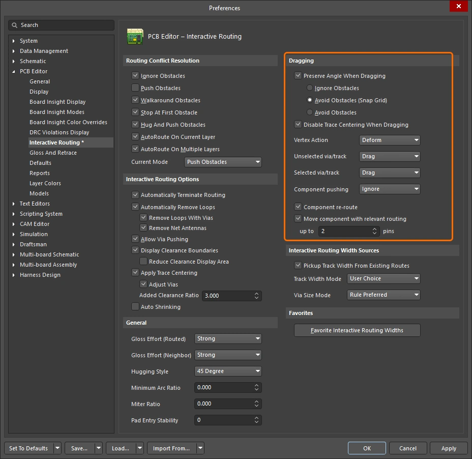 )의 Unselected via/track 또는 Selected via/track 옵션을 사용해 기본 드래그 동작을 변경하면 됩니다. )의 Unselected via/track 또는 Selected via/track 옵션을 사용해 기본 드래그 동작을 변경하면 됩니다. |
| What you snap to during sliding | 슬라이딩 중인 라우팅은 현재 스냅 그리드에만 맞춰지는 것이 아니라, 객체 스냅 설정, 레이어 스냅 설정, 그리고 스냅 가이드 및 축 스냅 설정 활성화 여부에 따라 다른 객체에도 스냅될 수 있습니다( ). 인터랙티브 슬라이딩 중 스냅을 일시적으로 억제하려면 Ctrl 키를 누르고 있으십시오. 이 페이지의 시작 부분에는 cursor-snap behavior 요약이 있습니다. |
| Modifying T-junctions | T-접합을 인터랙티브하게 수정할 수 있도록 지원하는 전용 알고리즘도 포함되어 있습니다 - 접합점을 클릭하고 드래그하여 T-접합을 수정할 수 있습니다( ). |
| Dragging a via | 인접 라우트 글로싱 지원에 더해, 비아 드래그도 지원됩니다. 비아 드래그는 Neighbor Glossing 를 지원합니다(
). 비아 드래그 중 Tab를 눌러 패널에 접근하고 설정을 조정할 수 있습니다(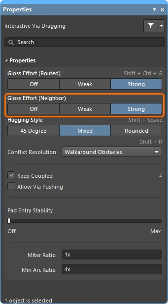 ). ). |
| Dragging a differential pair | 차동 페어의 구성원을 인식하기 위해 커플링 개념이 사용됩니다(
). 소프트웨어가 차동 페어에 속한 객체를 인식하면, Keep Coupled 옵션이 활성화된 경우 페어의 짝 트랙 또는 비아도 함께 드래그하려고 시도합니다( 짝 객체가 커플링되어 있는지 확인하기 위해, 소프트웨어는 다음을 검사합니다:
|
| Push or jump | 를 초과하지 않아야 합니다. 기존 패드와 비아는 건너뛰거나, 필요하고 가능할 경우 Allow Via Pushing 옵션이 활성화되어 있으면 비아를 밀어낼 수 있습니다( ). ). |
| Break a track segment | 단일 트랙 세그먼트를 분할하려면 먼저 해당 세그먼트를 선택한 다음, 중앙 정점 위에 커서를 놓고 클릭하여 드래그하면 새 세그먼트가 추가됩니다. |
| Object visibility | 현재 라우팅을 구성하는 객체를 더 쉽게 보려면, View Configuration 패널(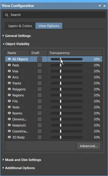 )에서 라우팅 객체의 Transparency를 조정하십시오. )에서 라우팅 객체의 Transparency를 조정하십시오. |
 ).
). ).
).Moving a Routed Component
보드를 라우팅하는 동안 추가 부품과 새로운 라우팅을 위한 공간을 만들기 위해 이미 라우팅된 부품의 위치를 조정해야 하는 경우가 드물지 않습니다. 이를 돕기 위해 PCB 편집기에는 라우팅 인지형 부품 이동 기능이 포함되어 있습니다.
이 도구에는 두 가지 측면이 있습니다. 하나는 새 위치에 맞도록 부품 패드까지의 라우팅을 복원하려고 시도하는 것이고, 다른 하나는 팬아웃, 이스케이프 라우트, 핀 간 라우트를 식별하는 것입니다. 이들을 통칭해 relevant routing 라고 하며, 부품 이동 중 이 라우팅 패턴을 정확히 유지하려고 시도할 수 있습니다(활성화된 경우).
Component re-route 옵션이 활성화되면 이동 중인 부품이 배치된 후 연결된 라우트가 복원됩니다.
이동된 부품 재라우팅 |
|
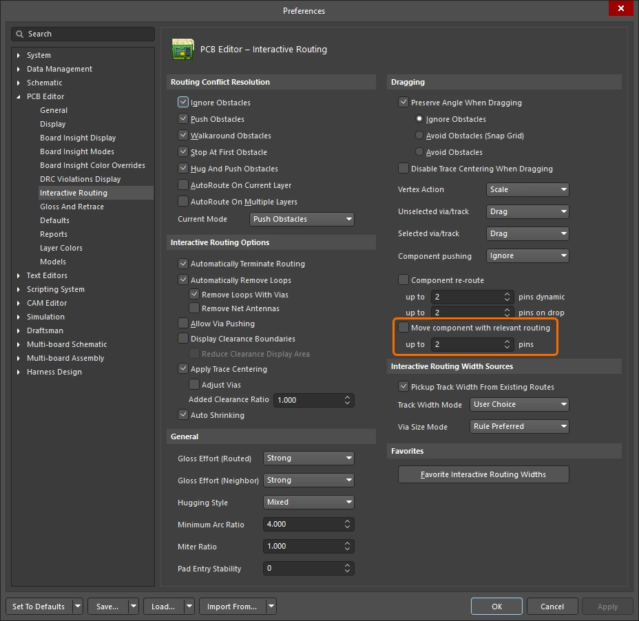
| Enable rerouting of moved component(s) | Preferences 대화상자(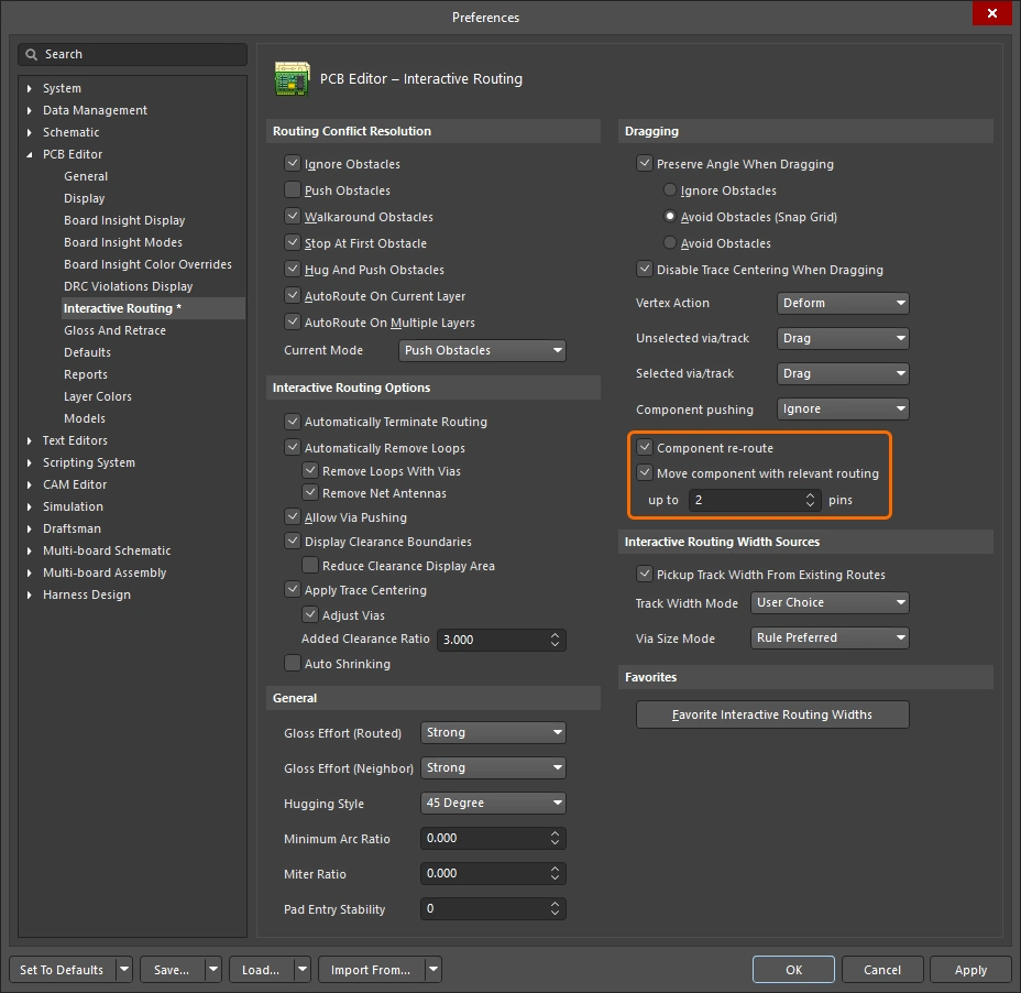 )에서 Component re-route 옵션을 활성화하거나, 이동 중 )에서 Component re-route 옵션을 활성화하거나, 이동 중 Shift+R 단축키를 사용해 켜고 끌 수 있습니다. 이 기능은 여러 부품을 한 번의 작업으로 이동하는 것도 지원합니다. |
| When does rerouting happen? | 기본적으로 이 기능은 부품 패드, 팬아웃 또는 이스케이프 라우트에서 라우팅을 끊은 다음, 이동 중인 부품이 배치되면 끊어진 연결을 다시 라우팅하려고 시도합니다. |
| Include relevant routing | 팬아웃, 이스케이프 라우트, 핀 간 라우트는 통칭하여 relevant routing이라고 합니다. Move component with relevant routing 옵션( |
 )
)아래 슬라이드는 라우팅 포함 부품 이동 기능의 각 기능을 제어하는 방법을 보여줍니다.
Glossing and Retracing Existing Routes
대화형 라우팅 엔진의 핵심 요소 중 하나는 글로싱 알고리즘입니다. 글로싱은 라우트를 세심하게 분석하여 코너 수를 줄이고, 라우트를 더 깔끔하고 짧게 만듭니다. 글로싱은 대화형 라우팅 중에 수행되며, 라우팅 중 커서를 움직이면 제안된 라우트 경로가 지속적으로 글로싱됩니다. 글로싱은 대화형 슬라이딩 중에도 수행되며, 기존 라우트를 드래그하면 해당 라우트는 물론 이동하는 라우트의 영향을 받는 인접 라우트도 지속적으로 글로싱됩니다. 글로싱은 후처리로도 수행할 수 있으며, 선택한 임의의 넷 집합에 적용할 수 있습니다. 라우팅이 어느 정도 강하게 글로싱되는지는 현재 글로스 강도에 따라 결정됩니다.
이 섹션에서는 후처리로서의 글로싱, 즉 기존 라우트의 글로싱에 중점을 둡니다. 관심 있는 라우트를 선택한 후 Gloss and Retrace 패널( )에서 글로스 설정을 구성한 다음 Route » Gloss Selected 명령을 실행하십시오.
글로싱 엔진에는 retrace 기능도 포함되어 있습니다. 이 기능은 라우팅 폭이나 차동 페어 간격처럼 설계 제약을 변경한 후 선택한 라우트를 그 변경 사항에 맞게 업데이트해야 할 때 사용합니다. Retrace를 사용하면 기존 전원 라우팅을 더 굵게 만들거나 차동 페어를 새로운 폭 및 간격 설정에 맞게 업데이트할 수 있습니다.
-
글로싱은 기존 트레이스 폭과 차동 페어 간격을 유지하면서 트레이스 형상을 개선하는 데 중점을 둡니다.
-
Retrace는 설계 제약을 충족하는 데 중점을 두며, 현재 제약 설정에 맞게 폭과 차동 페어 간격을 업데이트합니다.
Glossing Selected 명령에 대한 참고 사항
| What does Gloss Selected do? | 글로싱은 선택한 라우트를 분석하여 코너 수를 줄이고, 더 깔끔하고 짧게 만듭니다. 또한 품질이 좋지 않은 패드 진입부를 수정하고, 차동 페어 라우팅의 품질도 개선하려고 시도합니다. |
| What is Glossed? |
|
| What options control Gloss Selected? | Gloss Selected는 PCB Editor - Gloss and Retrace 대화상자(Preferences)의 |
| Glossing a differential pair |
|
| Support for room-based rules |
|
| Support for Subnet Jumpers | Gloss는 Subnet Jumper 트랙을 고정된 것으로 취급합니다. |
| Exclusions |
|
| Gloss Selected feedback |
|

Retrace Selected 명령에 대한 참고 사항
| What does Retrace Selected do? |
|
| What is Retraced? |
|
| What options control Retrace Selected? | Retrace는 PCB Editor - Gloss And Retrace 의 Preferences 대화상자 또는 Gloss And Retrace 패널에 설정된 현재 값을 따릅니다. |
| Updating the vias in Retraced routes | Retrace는 적용 가능한 Routing Width 설계 제약 또는 Gloss and Retrace 패널의 Set Width 필드에 입력된 값에 따라 트랙과 아크의 폭을 업데이트합니다. 하지만 Routing Via Style 설계 제약의 변경을 반영하도록 배선 비아를 업데이트하지는 않습니다. 비아 크기 변경을 반영하려면 다음과 같이 하십시오.
|
| Retracing a differential pair | 차동 페어 간격 업데이트에 Retrace를 사용할 수 있습니다.
|
| Retrace feedback |
|
 ).
).Gloss 및 Retrace Selected Routing 옵션
PCB Editor – Gloss And Retrace 페이지의 Preferences 대화상자( )와 Gloss And Retrace 패널()은 PCB 설계 작업 공간에서 Gloss Selected 및 Retrace Selected 기능과 관련된 다양한 제어 옵션을 제공합니다.
Gloss & Retrace Parameters |
|
Hugging Style  |
|
Avoid polygons  |
활성화하면 Gloss Selected 또는 Retrace Selected 명령을 실행할 때 기존 폴리곤을 존중합니다. 이 옵션이 비활성화되면 기존 폴리곤은 무시되고(그 위로 배선됨), 영향을 받은 폴리곤은 이후 다시 repour할 수 있습니다. |
Avoid rooms  |
활성화하면 Gloss Selected 또는 Retrace Selected 명령을 실행할 때 기존 room을 존중합니다. 설계에 특정 routing width 요구사항으로 범위가 지정된 room이 정의되어 있고 gloss/retrace할 배선이 그 room을 가로지르지 않는 경우, 이 옵션이 활성화되어 있으면 결과 배선도 해당 room을 가로지르지 않습니다. 이 옵션이 비활성화되면 기존 room을 가로질러 배선되며, 그러한 room 내부에서 사용할 폭은 room 기반 규칙의 제약에 정의된 값이 사용됩니다. |
Pad Entry Stability  |
중심 정렬된 패드 진입을 보호합니다. 원하는 수준(환경설정)을 입력하거나 슬라이더 바(패널)를 사용하여 보호 수준을 설정합니다. ' |
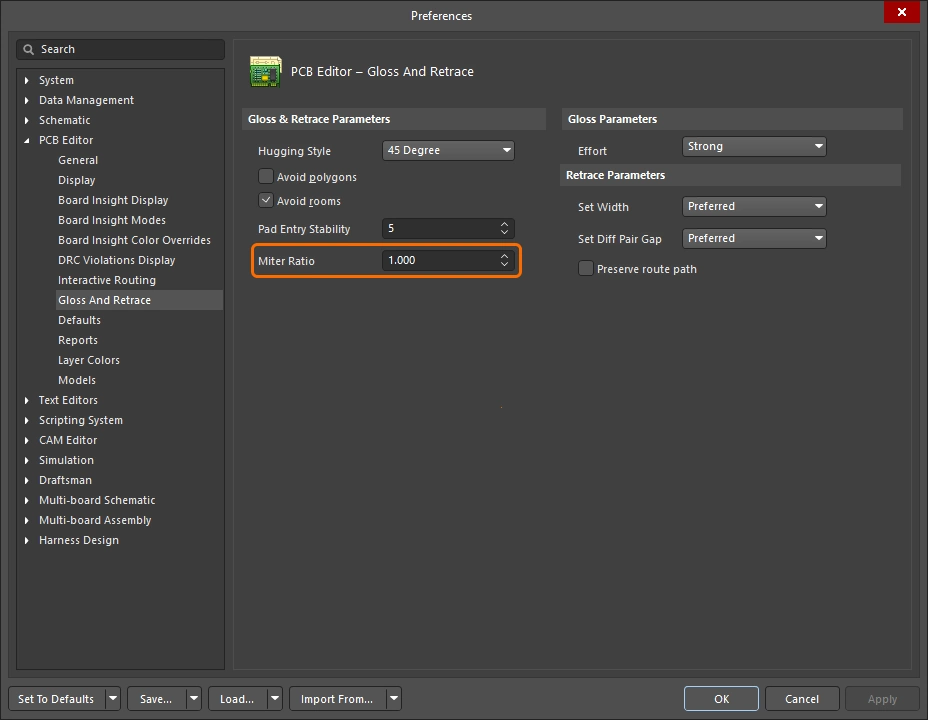
Miter Ratio  |
최소 코너 타이트니스(tightness)를 제어합니다. Miter Ratio에 현재 트랙 폭을 곱한 값은, 해당 비율에서 배선 가능한 가장 타이트한 U자형의 벽 사이 간격과 같습니다. 0 이상인 양의 값을 입력하십시오. |
Effort  |
다음 선택지 중 원하는 gloss 수준을 선택하십시오.
|
Set Width  |
드롭다운을 사용하여, Retrace Selected 명령 실행 시 적용 가능한 Width 또는 Differential Pairs Routing 설계 제약의 규칙 기반 폭 옵션(Min / Max / Preferred) 중 하나를 선택하거나 Current 폭으로 retrace하십시오. 또는 원하는 사용자 지정 폭 값을 필드에 직접 입력할 수도 있습니다. |
Set Diff Pair Gap  |
드롭다운을 사용하여, Retrace Selected 명령 실행 시 적용 가능한 Differential Pairs Routing 설계 제약의 규칙 기반 간격 옵션(Min / Max / Preferred) 중 하나를 선택하거나 차동 페어 트랙 사이를 Current 간격으로 retrace하십시오. 또는 원하는 사용자 지정 간격 값을 필드에 직접 입력할 수도 있습니다. 이 옵션은 Hugging Style 에 대해 45 Degree 옵션이 선택된 경우에만 사용할 수 있습니다. |
Preserve route path  |
Retrace 중 정확한 트레이스 형상을 유지하려면 활성화하십시오. 이 옵션이 활성화되면 Retrace 알고리즘은 트레이스의 중심선을 수정하지 않습니다. 트랙 폭은 변경될 수 있고 서로 다른 폭의 세그먼트로 분할될 수 있지만, 경로 자체는 변경되지 않습니다. |
정보 및 경고 메시지
정보 메시지 ( |
|
Skipped immovable + <Descriptor> |
객체가 Gloss/Retrace로부터 보호되어 있습니다. 예: 잠겨 있거나 부품에 속한 경우. 최대 개수 20, 클릭 가능. |
Skipped subnet jumper + <Descriptor> |
서브넷 점퍼는 그대로 유지되며, 각 경우마다 사용자에게 알립니다. 최대 개수 20, 클릭 가능. |
Skipped reflex angle + <Descriptor> |
180도를 초과하는 아크는 글로싱되지 않습니다. 최대 개수는 20개이며, 클릭할 수 있습니다. |
Skipped objects in user-defined Union |
유니언에 속한 객체는 글로싱되지 않습니다(Length Tuning 유니언에는 적용되지 않음). 관련된 각 유니언당 한 번만 표시됩니다. 최대 개수는 20개이며, 클릭할 수 있고, 유니언의 바운딩 사각형으로 확대됩니다. |
Command does not apply to arcs (Retrace only) |
Retrace는 아크를 지원하지 않습니다. 최대 개수는 1개이며, 클릭하면 처음 발견된 아크로 확대됩니다. |
 )
)경고 메시지 |
|
Applicable Diff Pair Routing rule not found for some object(s) + <Descriptor> |
일부 Gloss / Retrace 대상이 차동 페어 넷에 속해 있지만, 적용 가능한 Diff Pair Routing 규칙이 없습니다. 이 경우 명령은 해당 대상을 비차동 페어 객체로 처리하므로, 페어의 두 선이 서로 멀어지도록 Gloss 처리될 수 있습니다. 최대 개수는 1개이며, 클릭할 수 있습니다. |
Applicable Width rule not found for some object(s) + <Descriptor> |
Retrace는 Min에서 Preferred Width까지의 규칙 설정을 사용합니다. 적용 가능한 Width 규칙이 없으면 현재 폭이 유지됩니다. 최대 개수는 1개이며, 클릭할 수 있습니다. |
Pre-existing Min Width violation(s) detected + <Descriptor> |
Retrace는 Min에서 Preferred Width까지의 규칙 설정을 사용하며, DRC 위반이 발생하지 않으면 preferred를 사용하고, DRC 위반을 피하기 위해 필요하면 더 작은 값을 사용합니다. 따라서 DRC 문제가 없는 트랙은 처음부터 최소 Min Width 이상이었다면 계속 DRC 문제가 없는 상태를 유지합니다. 이보다 더 좁았다면 Min 폭으로 설정할 때 DRC 위반이 발생할 수 있습니다. 이 메시지는 실제 DRC 위반 발생 여부와 관계없이 이러한 상황을 경고합니다. 메시지를 클릭할 수 있을 때쯤이면 원래의 얇은 객체는 이미 더 넓어졌고 위치도 변경되었을 수 있습니다. 어떤 일이 일어났는지 확인하려면 Undo가 필요할 수 있습니다. 최대 개수는 1개이며, 클릭할 수 있습니다. |
대화형 라우팅 및 대화형 슬라이딩 옵션
새 연결을 대화형으로 라우팅하든, 추가 라우팅 공간을 만들기 위해 기존 라우트를 드래그(슬라이드)하든, 동일한 라우팅 기술이 많이 적용됩니다. 이 섹션에서는  , Interactive Sliding(), 그리고
  패널에서 사용할 수 있는 Interactive Via Dragging(Properties) 옵션을 요약합니다. 이러한 기능의 기본 설정은 PCB Editor 대화상자의 Preferences 섹션(
 )에서 구성됩니다.
충돌 해결 


이 옵션은 라우팅/슬라이딩 객체가 기존 객체를 만났을 때 어떻게 반응할지 결정합니다. 라우팅 또는 슬라이딩 중에 Shift+R 단축키를 눌러 사용 가능한 모드를 순환하거나, Tab를 눌러 Properties 패널을 열고 필요한 설정을 선택할 수 있습니다.
대화형 라우팅 또는 대화형 슬라이딩 중 충돌 해결 모드에 대한 자세한 내용.
| Ignore Obstacles | 이 모드에서 대화형 라우터는 기존 객체 위를 포함해 어느 위치에나 트랙을 배치할 수 있으며, 잠재적인 위반을 표시하지만 허용합니다. |
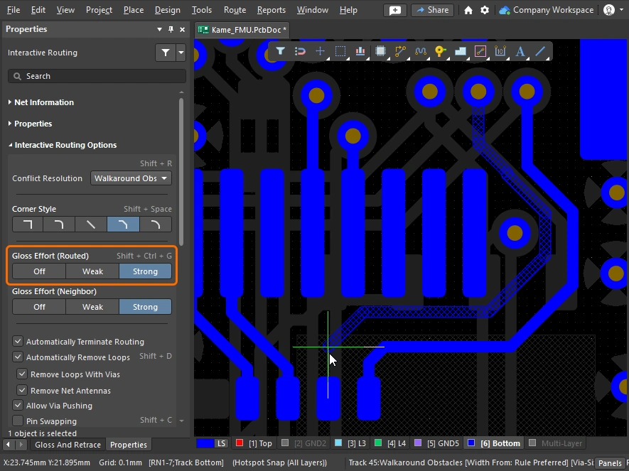
| Walkaround Obstacles | 기존 트랙, 패드, 비아와 같은 객체를 피해 마지막 클릭 위치에서 현재 커서 위치까지 경로를 찾으려고 시도합니다. 다른 객체와의 이격거리는 적용 가능한 Clearance 설계 규칙으로 정의됩니다. 이 모드에서 위반 없이 장애물을 우회할 수 없으면 라우트가 막혀 있음을 나타내는 표시가 나타납니다. |
| Push Obstacles | 새 라우트를 위한 공간을 만들기 위해 기존 트랙과 비아를 밀어냅니다. 이 모드에서 위반 없이 장애물을 밀어낼 수 없으면 라우트가 막혀 있음을 나타내는 표시가 나타납니다. 비아 밀어내기는 Allow Via Pushing 옵션으로 제어됩니다. |
| HugNPush Obstacles | 라우팅은 기존 객체를 가깝게 따라가며, 현재 라우팅 중인 트랙을 위한 공간이 부족할 때만 이를 밀어냅니다. 이 모드에서 위반 없이 장애물을 따라가거나 밀어낼 수 없으면 라우트가 막혀 있음을 나타내는 표시가 나타납니다. |
| Stop at First Obstacle | 라우팅은 진행을 방해하는 첫 번째 장애물에서 멈춥니다. |
| Autoroute Current Layer | 자동 라우터의 지능을 대화형 라우터에 적용하여, 현재 레이어에서 전체 라우트 길이가 가장 짧아지도록 밀어내기와 우회를 자동으로 선택합니다. |
| Autoroute MultiLayer | 자동 라우터의 지능을 대화형 라우터에 적용하여, 전체 라우트 길이가 가장 짧아지도록 밀어내기, 우회 또는 레이어 전환을 자동으로 선택합니다. |
코너 스타일 
대화형 라우팅 중 코너를 형성하는 트랙과 아크의 모양을 corner style라고 합니다. 대각선 코너가 가장 일반적이지만, 아크를 배치해 만드는 곡선 코너도 많이 사용됩니다.
대화형 라우팅(슬라이딩) 중 Shift+Spacebar를 눌러 5가지 코너 스타일을 순환하고, Spacebar를 눌러 코너 방향을 전환하거나, Tab를 눌러 Properties 패널을 엽니다.
대화형 라우팅 또는 대화형 슬라이딩 중 코너 스타일 제어에 대한 자세한 내용.
Track 45 |
45도 트랙을 사용해 코너를 만듭니다(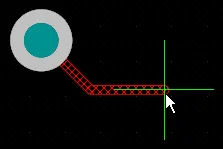 ). ). Spacebar를 눌러 코너 방향을 전환합니다 (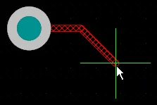 ). ). |
Track 45 with Arc |
트랙과 45도 아크를 사용해 코너를 만듭니다(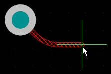 ). ). Spacebar를 눌러 코너 방향을 전환합니다(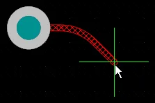 ). ). , 및 . 키를 사용해 아크 반경을 대화형으로 변경하고, Shift를 누른 채로 있으면 반경 변경이 빨라집니다. |
Track 90 |
서로 90도를 이루는 두 개의 트랙을 사용해 코너를 만듭니다( ). ). Spacebar를 눌러 코너 방향을 전환합니다( ). ). |
Track 90 with Arc |
트랙과 90도 아크를 사용해 코너를 만듭니다(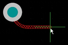 ). ). Spacebar를 눌러 코너 방향을 전환합니다( ). ). , 및 . 키를 사용해 아크 반경을 대화형으로 변경하고, Shift를 누른 채로 있으면 반경 변경이 빨라집니다. |
Any Angle |
마지막으로 배치한 세그먼트에서 현재 커서 위치까지 직접 다음 세그먼트를 배치합니다( ). 이 모드는 Strong Glossing과 함께 사용하여 스네이크 라우팅을 수행할 수 있습니다. ). 이 모드는 Strong Glossing과 함께 사용하여 스네이크 라우팅을 수행할 수 있습니다. |
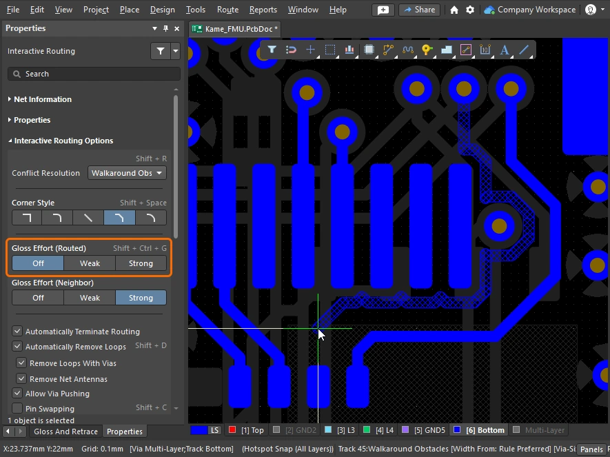
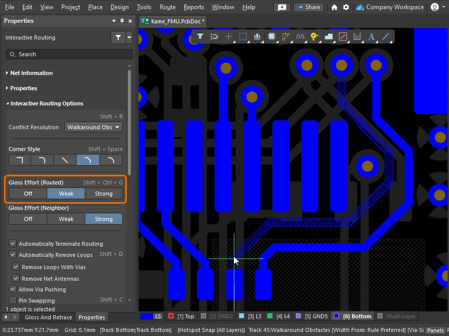
글로스 강도(라우팅 대상) 


대화형 라우팅 또는 대화형 슬라이딩과 같은 라우팅 이벤트 중에 소프트웨어는 글로싱 엔진을 실행합니다. 글로싱 엔진은 현재 라우팅 이벤트에서 배치되었거나 영향을 받은 모든 세그먼트를 지속적으로 검토하여 결과 품질을 개선하려고 시도합니다. 적용되는 작업량을 Gloss Effort라고 합니다.
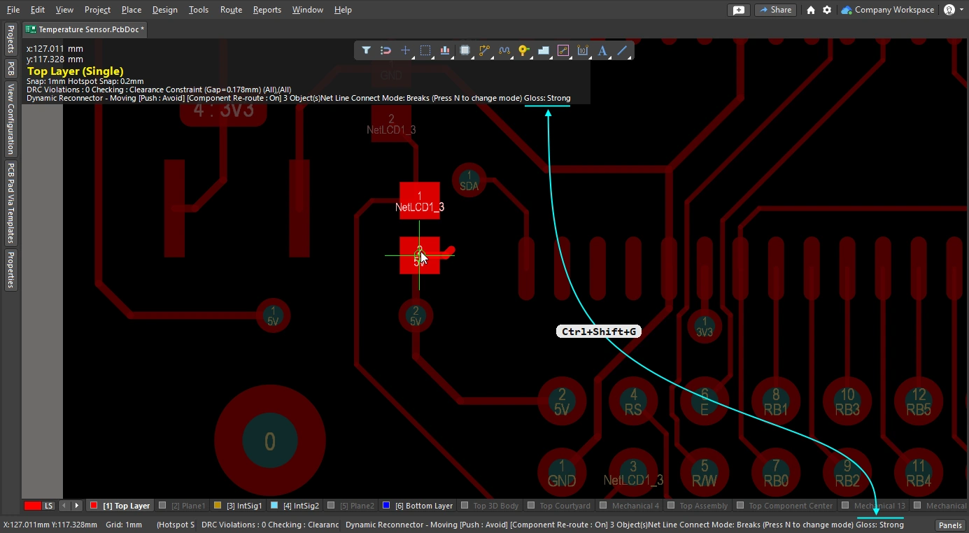
글로싱 품질의 척도에는 코너 수 감소, 세그먼트 수 감소, 예각 제거, 전체 라우트 길이 감소가 포함됩니다. 대화형 라우팅 또는 대화형 슬라이딩 중 Ctrl+Shift+G 단축키를 눌러 설정을 순환하거나, Tab를 눌러 Properties 패널을 열고 필요한 설정을 선택하십시오.
대화형 라우팅, 대화형 슬라이딩, 그리고 선택한 라우팅의 글로싱 또는 리트레이싱 중 글로스 강도에 대한 자세한 내용.
| Off | 이 모드에서는 글로싱이 사실상 비활성화됩니다. 그러나 예를 들어 겹치는 트랙 세그먼트를 제거하기 위한 정리 작업은 라우팅/드래깅 후에도 계속 수행됩니다. 이 모드는 일반적으로 보드 레이아웃의 마지막 단계에서 최고 수준의 미세 조정이 필요할 때 유용합니다(예: 트랙 수동 드래깅, 패드 진입부 정리 등). |
| Weak | 낮은 수준의 글로싱이 적용되며, Interactive Router는 현재 라우팅 중인 트랙(또는 드래그 중인 트랙/비아)에 직접 연결되었거나 그 주변 영역에 있는 트랙만 고려합니다. 이 글로싱 모드는 일반적으로 트랙 레이아웃을 미세 조정하거나 중요 라우트를 다룰 때 유용합니다. |
| Strong | 높은 수준의 글로싱이 적용되며, Interactive Router는 최단 경로를 찾고 트랙을 매끄럽게 정리하는 등의 작업을 수행합니다. 이 글로싱 모드는 일반적으로 레이아웃 프로세스의 초기 단계에서 보드의 많은 부분을 빠르게 라우팅하는 것이 목표일 때 유용합니다. |
대화형 슬라이딩 중에는 글로싱이 일시적으로 Weak로 낮아져, 설계자가 라우팅을 재배치하려는 작업을 글로싱 엔진이 방해하지 않도록 합니다.
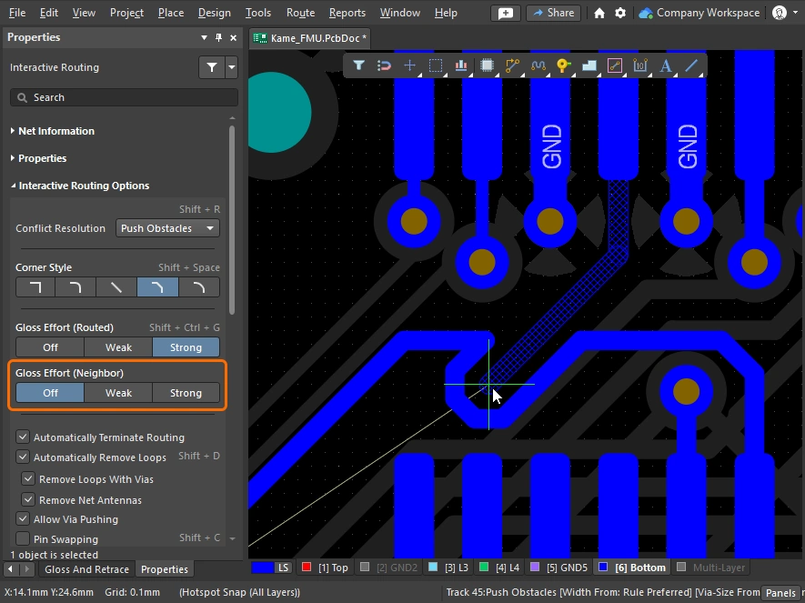
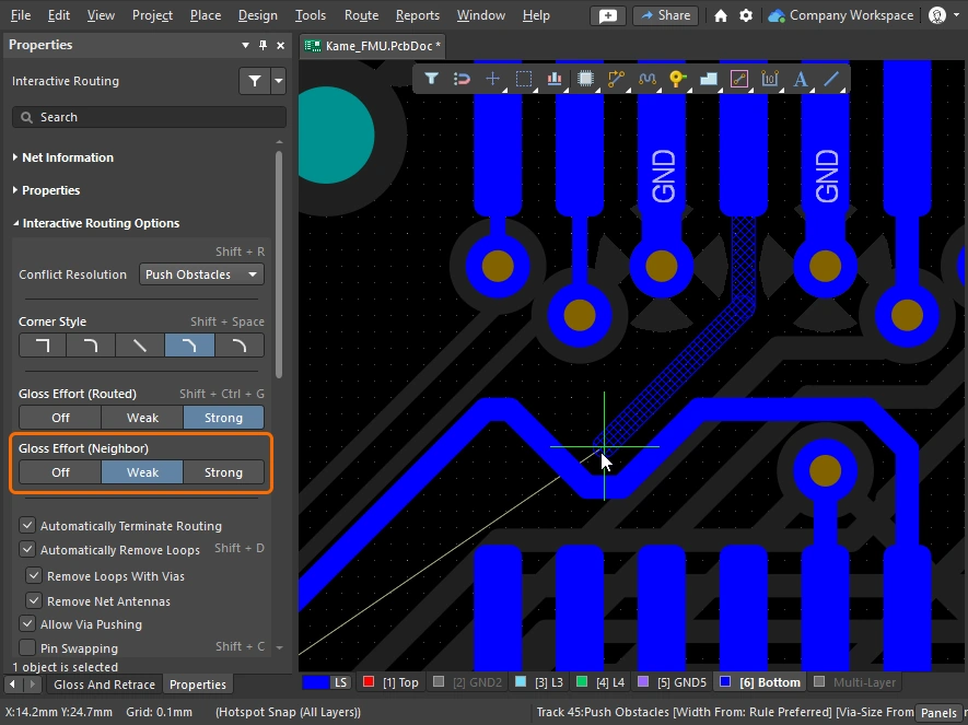
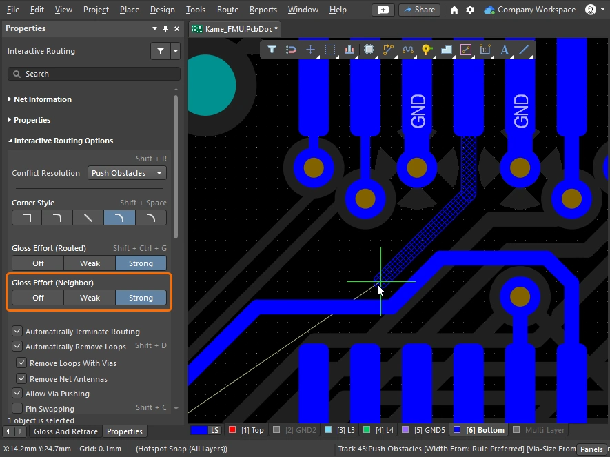
글로스 강도(인접 객체) 
Gloss Effort (Neighbor)는 현재 대화형 라우팅 또는 슬라이딩의 영향을 받는 인접 라우트에 적용되는 글로싱 양을 설정합니다. 이 역시 Off, Weak, Strong의 세 가지 설정이 있습니다.
Tab를 눌러 Properties 패널을 열고 필요한 설정을 선택하십시오.
대화형 라우팅 및 대화형 슬라이딩 중 글로스 강도에 대한 자세한 내용.
| Off | 이 모드에서는 글로싱이 사실상 비활성화됩니다. 그러나 예를 들어 겹치는 트랙 세그먼트를 제거하기 위한 정리 작업은 라우팅/드래깅 후에도 계속 수행됩니다. 이 모드는 일반적으로 보드 레이아웃의 마지막 단계에서 최고 수준의 미세 조정이 필요할 때 유용합니다(예: 트랙 수동 드래깅, 패드 진입부 정리 등). |
| Weak | 인터랙티브 라우터는 현재 라우팅 중인 트랙(또는 드래그 중인 트랙/비아)에 직접 연결되어 있거나 그 주변 영역에 있는 트랙만 고려하여 낮은 수준의 글로싱을 적용합니다. 이 글로싱 모드는 일반적으로 트랙 레이아웃을 미세 조정하거나 크리티컬 라우트를 다룰 때 유용합니다. |
| Strong | 인터랙티브 라우터가 최단 경로를 찾고, 트랙을 부드럽게 정리하는 등의 방식으로 높은 수준의 글로싱을 적용합니다. 이 글로싱 모드는 일반적으로 레이아웃 초기 단계에서 보드의 많은 부분을 빠르게 라우팅하는 것이 목표일 때 유용합니다. |
Hugging Style 


이 옵션은 인터랙티브 슬라이딩 중 코너 형상을 어떻게 처리할지를 제어하며, 슬라이드되는 트랙과 밀려나는 트랙 모두에 영향을 줍니다. 인터랙티브 슬라이딩 중 트랙 이동의 영향을 받는 기존 코너는 현재 Hugging Style에 따라 변환됩니다(45 Degree에서 Rounded로, 또는 Rounded에서 45 Degree로). 현재 Hugging Style은 선택한 라우트의 글로싱 또는 재추적 중에도 적용됩니다.
Shift+Spacebar 단축키를 사용해 세 가지 모드를 순환 전환할 수 있습니다.
인터랙티브 슬라이딩 중의 hugging 및 선택한 라우팅의 글로싱 또는 재추적 중의 hugging에 대해 자세히 알아보세요.
| 45 Degree | 슬라이딩 중 코너를 만들 때 항상 직선 직교/대각 세그먼트를 사용합니다(기존의 직교/대각 라우팅 동작에는 이 모드를 사용). |
| Mixed | 이동되거나 밀리는 대상이 직선이면 직선 트랙 세그먼트를 사용하고, 곡선이면 아크를 사용합니다. 최소 아크 크기는 Min Arc Ratio 옵션으로 제어됩니다. |
| Rounded | 이동/밀기와 관련된 각 버텍스에 아크를 사용합니다. snake routing에는 이 모드를 사용하고, 글로싱 시(인터랙티브 라우팅 및 수동 글로싱 중) 아크 + any angle 라우트를 사용하려는 경우에도 사용합니다. |
Vertex Action 

트랙이나 아크 세그먼트가 아닌 버텍스를 클릭하여 드래그할 때 적용되는 옵션입니다(버텍스는 두 세그먼트가 만나는 코너 위치입니다). 슬라이딩 중에는 Spacebar 단축키를 사용해 사용 가능한 모드를 순환 전환할 수 있습니다.
기타 라우팅 옵션
옵션에 단축키가 있으면 Properties 패널의 오른쪽에 자세히 표시됩니다. 각 설명에는 해당 옵션을 설정할 수 있는 위치를 보여주는 이미지가 포함되어 있습니다.
현재 라우팅 중인 연결이 대상 패드에 도달하면 해당 넷의 라우팅을 자동으로 중지하되, Interactive Routing 명령은 유지하여 다른 넷을 클릭해 바로 라우팅을 시작할 수 있도록 합니다. |
|
이 옵션을 활성화하면 기존 라우트에 대해 새 경로를 라우팅할 수 있으며, 새 라우트 경로가 기존 경로와 다시 만나면 중복된 루프가 자동으로 제거됩니다. |
|
| ↳ Remove Loops with Vias | 비아와 패드가 직접 연결된 경우, 루프 제거 후 더 이상 필요하지 않다고 판단되면 해당 비아는 제거됩니다. |
| ↳ Remove Net Antennas | 넷 안테나는 한쪽 끝이 종단되지 않은 라우팅 구간입니다. 현재 라우팅이 안테나가 접촉 중인 객체에 영향을 주면 이러한 구간은 자동으로 제거됩니다. |
Keep Coupled |
차동 페어에 속한 객체가 페어의 상대 트랙 또는 비아와 함께 드래그되도록 하려면 이 옵션을 선택합니다. |
Include Miters |
트랙 세그먼트를 드래그하는 동안 마이터를 포함하려면 이 옵션을 선택합니다. |
Merge Parallel |
드래그 중인 트랙 세그먼트가 기존의 고정된 세그먼트와 정렬되었을 때 서로 병합될 수 있도록 하려면 이 옵션을 선택합니다. |
| Push Obstacles 또는 HugNPush Obstacles 모드에서 비아를 밀 수 있도록 하려면 이 옵션을 선택합니다. | |
Pin Swapping |
이 넷에 대해 핀 스와핑을 활성화하려면 이 옵션을 선택합니다. 핀 스와핑 설정에 대해 자세히 알아보세요. |
현재 선택한 라우팅 폭으로는 장애물 사이를 통과할 수 없는 위치에서 라우팅이 가능하도록 라우팅 폭을 자동으로 줄이려면 이 옵션을 선택합니다. 폭은 해당 Routing Width 설계 제약이 허용하는 최소값까지 줄어들 수 있습니다. |
|
기존 객체 주변의 진입 금지 영역( |
|
| ↳ Reduce Clearance Display Area | 클리어런스 경계 표시를 현재 커서 위치 주변의 원형 영역( |
길이 게이지는 현재 라우트가 적용 가능한 Length 및 Matched Length 설계 규칙을 얼마나 잘 충족하는지 나타냅니다. Length Tuning에 대해 자세히 알아보세요. |
|
이 슬라이더는 중앙 정렬된 패드 진입을 보호하여, Glossing으로 인해 중앙 정렬된 트랙이 중심에서 벗어나는 것을 방지합니다(중앙 정렬된 트랙을 중심에 유지하지만, 중심에서 벗어난 트랙을 중앙으로 맞추지는 않습니다). 슬라이더 바를 사용해 보호 수준을 설정합니다. |
|
활성화하면 인터랙티브 라우팅 엔진이 라우트가 패드 사이를 지나가는 시점을 감지하고, 아래에 지정된 Added Clearance Ratio 를 해당 클리어런스 제약에 곱한 최대 거리까지 라우트를 중앙에 오도록 시도합니다. Adjust Vias sub-option이 활성화된 경우, 비아-비아 및 비아-패드 사이에도 트레이스 센터링을 적용할 수 있습니다. 필요한 경우 이 기능은 트랙 슬라이딩 중 비활성화할 수도 있습니다. |
|
이 옵션의 목적은 두 가지입니다:
비아를 제외하려면 Adjust Vias 옵션을 비활성화하세요. |
|
적용 가능한 클리어런스의 배수이며, 그 값이 클리어런스에 추가됩니다. 예를 들어 적용 가능한 클리어런스가 |
|
라우트를 인터랙티브 슬라이딩할 때 트레이스 센터링을 끄려면 이 옵션을 활성화합니다. 이 옵션이 활성화되면, 기본 Apply Trace Centering option이 활성화되어 있더라도 라우트의 인터랙티브 슬라이딩 중에는 트레이스 센터링이 적용되지 않습니다. |
|
Miter Ratio는 코너의 최소 조임 정도를 제어합니다. Miter Ratio에 현재 트랙 폭을 곱한 값은 해당 비율에서 라우팅 가능한 가장 좁은 U자 형상의 벽 사이 간격과 같습니다( |
|
Min Arc Ratio는 any angle 인터랙티브 라우팅 중과 Mixed Hugging Style의 인터랙티브 슬라이딩 중에 적용됩니다. 이 비율은 허용되는 최소 반경 아크를 결정하는 데 사용되며, 아크 반경이 이 최소값보다 작아지면 해당 아크는 트랙 세그먼트로 대체됩니다. 여기서:
|
|
라우팅된 PCB를 포함해 설계 프로세스의 어느 단계에서든 핀 스와핑을 지원하기 위해, PCB 편집기는 스와핑이 가능한 넷에 subnet jumper라고 하는 작은 라우팅 커넥터를 추가하거나 제거할 수 있습니다. subnet jumper는 소프트웨어가 쉽게 배치 및 제거할 수 있는 요소로 인식하는 짧은 트랙 세그먼트입니다. 이는 Add 및 Remove Subnet Jumper 명령을 Route 메뉴에서 수동으로 사용하여 처리할 수도 있고, 인터랙티브 라우팅 중 스와핑 가능한 핀으로 라우팅할 경우 라우팅 엔진이 자동으로 처리할 수도 있습니다. 이 값은 인터랙티브 라우팅 중 스와핑 가능한 넷에 추가되는 subnet jumper의 길이를 정의합니다. |


Net / Differential Pair Information 

대화형 라우팅/슬라이딩 및 차동 페어 라우팅/슬라이딩 중에는, 현재 편집 중인 넷이 Properties 패널 상단에 자세히 표시됩니다.
Name & Class |
현재 편집 중인 Net 또는 Differential Pair의 이름과, 속한 Class(있는 경우)가 표시됩니다. Name과 Class는 라이브 링크이므로, 클릭하면 관련 넷 또는 페어의 세부 정보를 표시하는 PCB 패널이 열립니다. |
Length & Delay |
Signal Length와 계산된 Delay도 표시되며, 이 값들은 최초 라우팅/슬라이딩 클릭이 발생한 시점에 유효한 값입니다. Length와 Delay 역시 라이브 링크이므로, 클릭하면 관련 넷 또는 페어의 세부 정보를 표시하는 PCB 패널이 열리며, 라우팅 또는 슬라이딩이 수행되는 동안 실시간으로 업데이트됩니다. |
Routing Properties 

대화형 라우팅 중에는 라우트 객체의 속성을 Properties 패널에서 편집할 수 있습니다.
| Layer | 멀티 라우트가 배치될 레이어입니다. 드롭다운을 사용해 다른 레이어를 선택하면 비아가 자동으로 추가됩니다. 또는 레이어 변경 단축키를 사용할 수도 있습니다. |
| Gap | 현재 라우트가 차동 페어인 경우 Gap 옵션이 표시되며, 드롭다운을 사용해 해당 차동 페어 라우팅 제약 조건에 정의된 Min/Preferred/Max 값으로 라우팅 간격을 설정할 수 있습니다. 차동 페어 라우팅에 대해 자세히 알아보세요. |
| Via Template | 배치되는 비아를 정의하는 제약 조건에서 Template Preferred 옵션이 활성화되어 있으면( 배치되는 비아를 정의하는 제약 조건에서 Min/Max Preferred 옵션이 활성화되어 있으면( 패드 및 비아 템플릿에 대해 자세히 알아보세요. |
| Via Hole Size | 사용될 비아 홀 크기를 표시합니다. 이 값은 해당 라우팅 비아 스타일 설계 제약 조건에서 허용하는 범위 내에서 직접 편집할 수 있습니다. |
| Via Diameter | 사용될 비아 직경을 표시합니다. 이 값은 해당 라우팅 비아 스타일 설계 제약 조건에서 허용하는 범위 내에서 직접 편집할 수 있습니다. |
| Width | 기존 라우트에서 클릭하여 라우팅을 시작하면, 기본 동작은 동일한 폭으로 라우팅하는 것입니다. 드롭다운을 사용해 해당 라우팅 폭 제약 조건에 정의된 Min/Preferred/Max 값으로 라우팅 폭을 설정할 수 있습니다. |
 )
) )
)Applicable Design Constraints (Rules) 
대화형/차동 페어 라우팅 중에는 현재 수행 중인 라우트에 적용되는 Routing Width 및 Routing Via Style 설계 제약 조건이 Properties 패널에 표시됩니다. 이들은 라이브 링크이므로, 필요 시 클릭하여 해당 설계 제약 조건을 열어 검토하거나 편집할 수 있습니다.
Via Constraint |
현재 라우팅 중인 넷에 적용되는 Routing Via Style 설계 제약 조건입니다. |
Width Constraint |
현재 라우팅 중인 넷에 적용되는 Routing Width 설계 제약 조건입니다. |
Dragging options
객체를 클릭한 뒤 드래그할 때 적용할 동작을 정의합니다.
| Preserve Angle When Dragging | 이 옵션을 활성화하면, 소프트웨어는 Properties 패널(
|
| Disable Trace Centering When Dragging | |
| Vertex Actions | 이 페이지 앞부분에서 자세히 설명함 |
| Unselected via/track | unselected비아 또는 트랙unselected을 드래그할 때 기본 동작을 Move 또는 Drag 작업으로 할지 정의합니다. 선택되지 않은 모드에 접근하려면 비아 또는 트랙을 클릭한 상태로 유지할 때 |
| Selected via/track | selected비아 또는 트랙selected을 드래그할 때 기본 동작을 Move 또는 Drag 작업으로 할지 정의합니다. 선택되지 않은 모드에 접근하려면 비아 또는 트랙을 클릭한 상태로 유지할 때 Ctrl 단축키를 누르십시오. |
| Component pushing | 이 필드는 설계 공간 내에서 컴포넌트를 이동할 때 현재의 Component Conflict Resolution 모드를 정의합니다. 이 기능에서는 컴포넌트가 selection bounding box로 식별됩니다. 다음 모드가 지원됩니다.
|
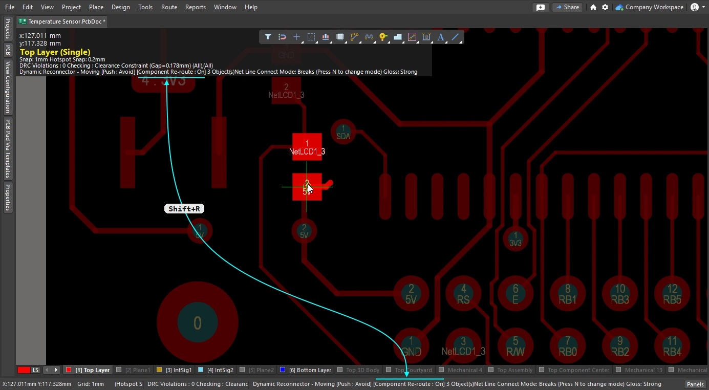
| Component re-route | 이 옵션을 활성화하면, 컴포넌트를 새 위치로 이동한 뒤 놓았을 때 소프트웨어가 끊어진 넷을 다시 연결하도록 컴포넌트 재라우팅을 시도합니다. 이동 중에는 Shift+R 단축키를 사용해 재라우팅 동작을 끄거나 켤 수 있습니다. 단, 이동된 컴포넌트가 유니온의 구성원인 경우에는 컴포넌트 재라우팅이 적용되지 않습니다. |
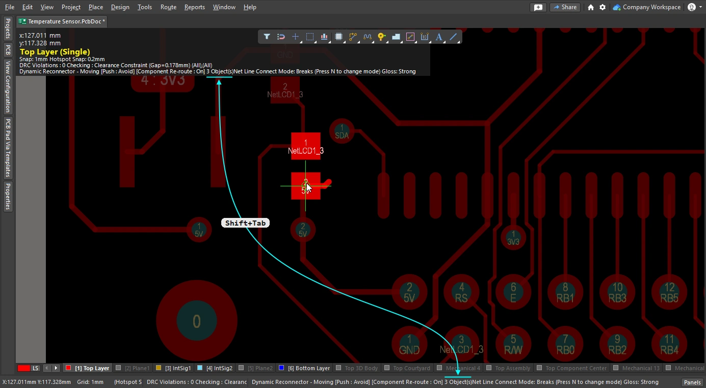
| Move component with relevant routing | 이 옵션을 활성화하면 관련 라우팅(Components +Via Fanouts +Escapes +Interconnects)을 포함한 상태로 컴포넌트 이동 작업을 시작합니다. Shift+Tab 단축키를 사용해 선택 집합을 순환할 수 있습니다. 이 옵션을 비활성화하면 컴포넌트만 선택된 상태로 이동 작업이 시작됩니다. 관련 라우팅 객체 집합은 이동 시작 전에 미리 감지되므로, 이 옵션이 비활성화된 경우에는 Shift+Tab 를 사용해 선택 집합을 순환할 수 없습니다.
|
 )
)Interactive Routing Width Source options 
대화형 라우팅 중 선택한 마지막 라우팅 폭과 비아 크기를 저장합니다. 대화형 라우팅 중에는 3 단축키를 눌러 모드를 순환할 수 있습니다.
선호 Width 옵션 
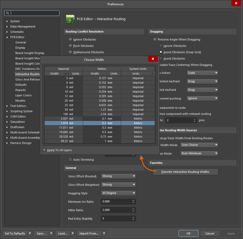
인터랙티브 라우팅 중 Shift+W 단축키를 누를 때 표시되는 사용자 정의 라우팅 폭 목록을 저장합니다( ).
).
| Favorite Interactive Routing Widths | 버튼을 클릭하면 Favorite Interactive Routing Widths 대화상자가 열리며, 여기서 인터랙티브 라우팅 중 Shift+W 단축키를 눌렀을 때 표시될 미리 정의된 폭 목록을 구성할 수 있습니다. |
 AI로 번역됨