
Простое размещение
Компонент можно перемещать, поворачивать и переворачивать в рабочем пространстве проектирования печатной платы. Для этого выберите нужный компонент в рабочем пространстве, щелкнув по нему. Выбранный компонент подсвечивается текущим цветом выделения, как показано на изображении ниже.
 Щелкните один раз, чтобы выбрать компонент.
-
Щелкните, удерживайте и перетащите, чтобы переместить выбранный компонент. Курсор перескочит в опорную точку компонента или в центр ближайшей площадки, если параметр Smart Component Snap включен на странице PCB Editor - General в диалоге Preferences. Нажмите клавишу Alt чтобы ограничить направление перемещения по горизонтальной или вертикальной оси в зависимости от начального направления движения.
-
Пока компонент перемещается вместе с курсором, нажмите Spacebar, чтобы повернуть его (Shift+Spacebar — чтобы повернуть в другую сторону). Шаг поворота по умолчанию — 90 градусов. Чтобы изменить этот параметр, используйте значение Rotation Step на странице PCB Editor - General диалога Preferences.
-
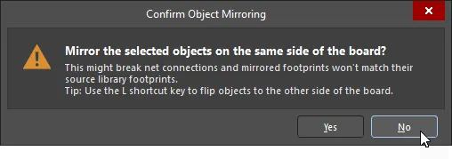
Пока компонент перемещается вместе с курсором, нажмите клавишу L, чтобы перевернуть его на другую сторону платы.
-
Нажмите Delete, чтобы удалить выбранный компонент с PCB.
 ).
).Линии соединений — отличное подспорье при размещении компонентов: они помогают находить и ориентировать компоненты, соединенные друг с другом. По мере перемещения компонента линии соединений динамически оптимизируются так, чтобы каждая линия соединения шла по кратчайшему пути к любому другому объекту с тем же именем цепи (net).

Используйте линии соединений, чтобы легче находить и ориентировать компоненты.
Чтобы уменьшить визуальную загроможденность, при перемещении компонента все линии соединений скрываются, кроме линий, подключенных к этому компоненту. Нажмите клавишу N для переключения режимов соединения линий цепей. Поддерживаются следующие режимы:
- Pad to Pad - во время перемещения линии соединений отображаются между площадками перемещаемого компонента и ближайшими площадками тех же цепей на плате.
- Breaks - во время перемещения линии соединений отображаются между площадками перемещаемого компонента и разрывами дорожек тех же цепей на плате.
- Hidden - линии соединений скрыты.
Текущий режим соединения линий цепей отображается в Status Bar и в Heads Up Display.
 Локализовано с помощью ИИ