
Подготовка производственных данных с помощью Output Jobs

Altium Essentials: Output Job File for Documentation
This content is part of the official Altium Professional Training Program. For full courses, materials and certification, visit Altium Training.
Для проекта печатной платы можно сформировать множество различных выходных данных, и у каждого типа вывода есть собственные настройки. Лучший способ управлять этим множеством — использовать файл Output Job, или, как его чаще называют, «OutJob».
OutJob — это предварительно настроенный набор выходных данных. Каждый вывод настраивается со своими параметрами и собственным форматом, например вывод в файл или на принтер. Настройки этих выводов хранятся в файле OutJob — это ASCII-файл, который становится частью проекта.
OutJob очень гибок: он может включать столько выходных данных, сколько требуется (как много, так и мало), и в проект можно добавить любое количество OutJob. Лучший подход — использовать один OutJob для настройки всех выходных данных, необходимых для каждого конкретного типа выпускаемой из проекта документации. Например, все выходные данные, необходимые для изготовления «голой» платы, помещаются в один OutJob, все выходные данные для сборки платы — во второй OutJob, и так далее.
OutJob также может содержать проверки валидационного типа, такие как отчеты ERC и DRC. Эти отчеты полезны как финальная проверка «на добро» непосредственно перед генерацией выходных данных, а затем могут храниться как подтверждение того, что проект был готов к выпуску.
Благодаря переносимости OutJob их можно повторно использовать между проектами, копируя файл Output Job из одного проекта в следующий и затем при необходимости перенастраивая источник данных (Data Source).
Подводя итог, использование OutJob дает ряд преимуществ:
-
Все выходные данные настраиваются и генерируются из одного места.
-
При необходимости несколько выходных данных можно объединить в один выходной файл — например, печать схем и печать топологии платы можно вывести в один PDF.
-
OutJob используются в проекте Workspace, что позволяет выполнять контролируемый выпуск (release) проекта.
-
Файлы OutJob можно копировать из одного проекта в другой, гарантируя, что всегда используются предпочтительные для вашей компании настройки вывода.
Добавление и определение Outjob
OutJob определяются с помощью редактора OutputJob. Создайте новый файл Output Job следующим образом:
- Используя команду File » New » Output Job File .
- Щелкнув правой кнопкой по имени проекта в панели Projects и выбрав Add New to Project » Output Job File в появившемся контекстном меню.
Файлы Output Job после добавления в проект отображаются в панели Projects в подпапке Settings\Output Job Files.
Создание Outjob в Workspace
Вы также можете воспользоваться контентом, размещенным в Workspace, и создать Output Job в подключенном Workspace:
-
Откройте вкладку Templates страницы Data Management – Templates в диалоге Preferences.
-
Выберите команду Output Job из меню кнопки Add или из контекстного меню таблицы шаблонов.

-
После выбора команды нажмите OK в открывшемся диалоге Close Preferences, чтобы закрыть диалог Preferences и открыть временный редактор OutputJob. Запланированная ревизия нового output job будет создана автоматически в папке Workspace типа
Output Jobs. -
Настройте output job по необходимости, как описано ниже на этой странице.
-
Сохраните output job в подключенный Workspace, выбрав в главном меню команду File » Save to Server. Появится диалог Edit Revision, в котором можно задать Name и Description создаваемого в Workspace output job, а также при необходимости добавить примечания к выпуску (release notes).
Сохранение существующего локального Output Job в Workspace
Если у вас уже есть файл output job (*.OutJob), вы также можете сохранить этот файл напрямую в Workspace. Процесс следующий:
-
Откройте файл output job в Altium Designer.
-
Выберите в главном меню команду File » Save to Server.
-
Появится диалог Choose Planned Item Revision. Используйте его, чтобы выбрать целевой Workspace Output Job, в следующую ревизию (или в уже существующую ревизию в состоянии
Planned) которого будет сохранен файл, затем нажмите OK. -
Появится диалог Edit Revision, в котором можно задать Name, Description и при необходимости добавить release notes.
-
После нажатия OK файл будет сохранен и помещен в ревизию Workspace Output Job.
Редактирование Workspace Output Job
На любом этапе вы можете вернуться к Output Job в Workspace и отредактировать его. На вкладке Templates страницы Data Management – Templates page диалога Preferences щелкните правой кнопкой по записи output job и выберите в контекстном меню команду Edit. Откроется временный редактор, при этом output job из последней ревизии Workspace Output Job будет открыт для редактирования. Внесите необходимые изменения, затем сохраните output job в следующую ревизию Workspace Output Job.
Добавление Workspace Output Job в проект
Workspace Output Job можно использовать в проектах разработки.
Выберите ревизию Workspace Output Job для использования на вкладке Managed OutputJobs tab диалога Project Options. Нажмите кнопку ![]() — появится диалог Select configuration item (Output Jobs), в котором перечислены последние ревизии всех Output Jobs в Workspace, доступных вам. Выберите нужный Output Job и нажмите OK.
— появится диалог Select configuration item (Output Jobs), в котором перечислены последние ревизии всех Output Jobs в Workspace, доступных вам. Выберите нужный Output Job и нажмите OK.

Ручной выбор ревизии outputjob на вкладке Managed OutputJobs диалога Project Options.
Options and Controls of the Select configuration item (Output Jobs) Dialog
Grid — доступные элементы конфигурации перечислены в разрезе Name, Description, Item Revision и Revision State. Выберите нужный элемент конфигурации из списка, затем нажмите OK, чтобы добавить выбранный элемент на вкладку Managed OutputJobs tab диалога Project Options.
Контекстное меню (правая кнопка)
-
Select Columns — нажмите, чтобы открыть диалог Select Columns и выбрать, какие столбцы отображать в диалоге.

Диалог Select Columns- Known Columns — перечисляет доступные столбцы, которые сейчас не отображаются.
- Selected Columns — перечисляет столбцы, которые отображаются в данный момент.
- Add — нажмите, чтобы добавить выбранный в данный момент Known Columns (не отображается) в область Selected Columns (отображается).
- Remove — нажмите, чтобы добавить выбранный в данный момент Selected Columns (отображается) в область Known Columns (не отображается).
-
All — нажмите, чтобы переместить все столбцы из области Selected Columns (отображается) в область Known Columns (не отображается).
Продолжайте добавлять дополнительные ревизии разных Output Jobs по мере необходимости. После нажатия OK для выхода из диалога Project Options выбранные outputjob(ы) появятся в панели Projects. Workspace OutputJob отличается в панели Projects значком ![]() .
.

Добавленные ревизии outputjob будут отражены в панели Projects.
Using a Workspace Output Job as Part of an Environment Configuration
Workspace Output Job также можно использовать как элемент конфигурационных данных в одной или нескольких определенных Environment Configurations. Конфигурация среды (environment configuration) используется для ограничения рабочей среды разработчика так, чтобы применялись только утвержденные компанией элементы проектирования. Конфигурации среды определяются и хранятся в Team Configuration Center — сервисе, предоставляемом через Workspace.
После подключения к Workspace и выбора (если применимо) из доступных вам конфигураций среды, Altium Designer будет настроен в части использования конфигураций Output Job. Если выбранная конфигурация среды содержит одну или несколько определённых ревизий outputjob, то only можно использовать эти определённые конфигурации. Если выбранная применимая к вам конфигурация среды не содержит указанных/добавленных ревизий outputjob, то они останутся доступными для ручного определения. Иными словами, вы можете вручную повторно использовать конфигурацию Output Job, размещённую в Workspace, и/или использовать локальные шаблоны. Дополнительные сведения см. в Environment Configuration Management (Altium 365 Workspace, Enterprise Server Workspace).
При принудительном применении конфигурации среды Altium Designer будет настроен в части использования Output Jobs в следующих областях.
-
Project Options Dialog – ревизии outputjob задаются для использования на вкладке Managed OutputJobs tab в диалоге Project Options, практически так же, как и при их ручном повторном использовании. Отличие при использовании под управлением конфигурации среды в том, что вы можете only добавлять те ревизии outputjob, которые определены для данной конфигурации среды.
-
Нажмите кнопку
 — появится диалог Select configuration item (Output Jobs).
- Используйте этот диалог, чтобы выбрать, какой OutJob использовать для проекта, из списка ревизий outputjob, определённых как часть текущей применённой конфигурации среды.
- При необходимости добавьте дополнительные ревизии outputjob.
- После добавления всех требуемых ревизий outputjob OK выйдите из диалога Project Options — выбранная(ые) ревизия(и) outputjob появится(ятся) на панели Projects.
-
Нажмите кнопку
- Creating a New OutJob File – хотя вы можете повторно использовать только те ревизии outputjob, которые указаны в активной конфигурации среды, при необходимости вы всё равно можете создавать новые файловые output jobs. Поэтому команды создания нового OutJob — либо с помощью команды File » New » Output Job File, либо через щелчок правой кнопкой по записи проекта на панели Projects и выбор Add New to Project » Output Job File — по-прежнему будут доступны.
- Trying to use an Existing OutJob File – при управлении конфигурацией и при наличии хотя бы одного OutJob, определённого для активной конфигурации среды, это станет невозможным. Если вы попытаетесь добавить в проект существующий файл Output Job, щёлкнув правой кнопкой по записи проекта на панели Projects, выбрав Add Existing to Project и указав этот файл, появится диалог предупреждения — он сообщит, что Output Jobs управляются применённой конфигурацией среды и что существующие файлы Output Job нельзя добавлять в проект.
Когда Workspace Output Job добавлен в проект и открыт, редактор OutputJob будет показывать, что файл является Managed OutputJob Document, с указанием ревизии элемента (Item Revision), его описания и родительского Workspace, в котором находится этот Output Job.

Редактор Output Job при просмотре Workspace Output Job.
Для Workspace Output Job любые элементы управления, которые иначе могли бы каким-либо образом повлиять на его изменение, отключены. Поэтому следующие возможности ARE NOT недоступны:
- Добавление новых Output Generators.
- Настройка существующих Output Generators.
- Вырезание, копирование, вставка, дублирование или удаление существующего Output Generator.
- Добавление новых Output Containers или Hard Copy Jobs.
- Настройка существующего Output Container или Hard Copy Job.
- Вырезание, копирование, вставка или удаление существующих Output Containers или Hard Copy Jobs.
- Переключение состояния включения Output Generator относительно допустимого Output Container или Hard Copy Job.
Однако вы по-прежнему можете определить использование вариантов (variant) для OutJob.
 Document Options dialog
Элементы OutJob
Настройка OutJob выполняется в три шага:

Составные элементы OutJob — все определяются и управляются в редакторе OutputJob.
- Add and configure the required outputs – выходные данные (outputs) группируются по функциональным категориям, таким как Assembly Outputs, Fabrication Outputs и Report Outputs. Строго говоря, выходные данные получаются путём запуска связанного Output Generator, настроенного соответствующим образом и использующего в качестве источника данных указанный документ в проекте (или сам проект).
- Add and configure the required output formats – генерация любого типа выходных данных требует сопоставления этого output с соответствующим (и применимым) форматом вывода. Это может быть либо один из поддерживаемых Output Containers (PDF, Folder Structure, Video), либо Hard Copy (вывод на печать). Несколько outputs могут быть сопоставлены одному и тому же контейнеру или hard copy, а пользователь управляет тем, где и как формируется вывод (любые параметры носителя, связанные с контейнером/hard copy).
- Set the variant choice – Altium Designer позволяет формировать выходные данные PCB‑проекта, используя базовый (без вариантов) дизайн или назначив использование определённого варианта этого дизайна. Можно выбрать вариант для каждого применимого output или один вариант, который будет применён ко всем применимым outputs в файле.
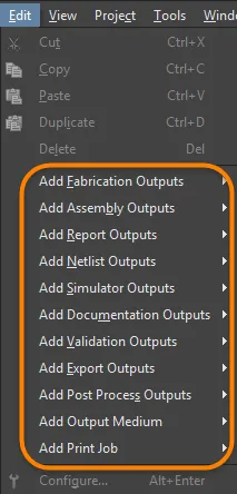
Добавление outputs в OutJob
Добавьте новый output требуемого типа, щёлкнув по соответствующему тексту Add New [type] Output внизу категории, затем выбрав нужный тип output во всплывающем меню. Либо выберите соответствующую команду в основном меню Edit .

Добавьте каждый требуемый output, выбрав соответствующий Data Source.
Типы outputs, для которых в проекте доступны соответствующие исходные данные, будут отображаться как доступные, а все остальные типы outputs — как недоступные (серым цветом).
Предоставляется второе меню, в котором можно указать Data Source, то есть какие исходные документы будут использоваться при генерации output. Для каждого output доступны только применимые источники данных, что снижает вероятность ошибок.
Data Source зависит от конкретного output. PCB‑связанные outputs, такие как PCB Prints, Gerber Files и Testpoint Reports, будут использовать документ PCB‑дизайна в качестве Data Source. Data Source для BOM может быть одним конкретным исходным документом схемы, документом PCB‑дизайна или всеми исходными документами схем. Последний вариант представлен пунктом [Project].
Для некоторых outputs список Data Source будет включать [Project Physical Documents]. Используйте этот вариант, если физический дизайн (то, как проект будет реализован на плате) должен быть аннотирован иначе, чем логический дизайн (исходные схемы). Это потребуется, если проект включает Device Sheets или использует возможности многоканальности и предпочтительна простая плоская схема аннотирования.
Максимальная повторная используемость — делаем Output Job универсальным
При настройке outputs доступен ряд инновационных функций, позволяющих сделать итоговую конфигурацию Output Job максимально универсальной. Сохраняя OutJob универсальным, вы можете эффективно повысить возможность его повторного использования в будущих проектах.
Generic Data Source Names
Многие генераторы outputs используют в качестве источника конкретный документ с заданным именем, из которого формируются соответствующие выходные данные — например, Gerber‑файлы, генерируемые из PCB‑документа FluxTriangulator.PcbDoc. Однако это «привязывает» конфигурацию Output Job и делает её полезной только для родительского проекта этого документа. Чтобы избежать привязки к конкретике, для многих генераторов outputs доступен универсальный (generic) пункт выбора для базового Data Source. В следующей таблице приведено, какие генераторы outputs поддерживаются и какие универсальные пункты (пункт(ы)) доступны.
| Категория | Тип вывода | Запись универсального источника данных |
|---|---|---|
| Выводы нетлиста | Все | [Project] |
| Выводы симулятора | Смешанное моделирование SIMetrix SIMPLIS |
[Project] |
| Выводы документации | Составной 3D-печать PCB 3D-видео PCB Печать PCB PDF3D |
[PCB Document] |
| PDF3D MBA | [MBA Document] | |
| Печать схем | [Project Physical Documents] | |
| Выводы для сборки | Все | [PCB Document] |
| Выводы для производства | Все | [PCB Document] |
| Выводы отчётов | Ведомость материалов (BOM) | [Project] [ActiveBOM Document] |
| Перекрёстная ссылка компонентов Экспорт комментариев Отчёт по иерархии проекта Отчёт по сетям с одним выводом |
[Project] | |
| Выводы проверки | Проверки BOM | [ActiveBOM Document] |
Состояния компонентов Соответствие конфигурации |
[Project] | |
| Проверка правил проектирования (DRC) Отчёт о различиях Отчёт сравнения посадочных мест |
[PCB Document] | |
| Выводы экспорта | Ansoft Neutral (AutoPCB) Ansys EDB AutoCAD dwg/dxf PCB Экспорт IDF Экспорт PARASOLID Экспорт STEP Экспорт VRML Hyperlynx (AutoPCB) MathWorks (AutoPCB) P-CAD ASCII (AutoPCB) Сохранить как/Экспорт PCB Specctra Design PCB |
[PCB Document] |
| MBA Экспорт PARASOLID MBA Экспорт STEP |
[MBA Document] | |
| AutoCAD dwg/dxf Schematic OrCAD v7 Capture Design (AutoSCH) P-CAD V16 Schematic Design (AutoSCH) Сохранить как/Экспорт схемы |
[Project] | |
| Выводы постобработки | Копировать файлы | [Project] |
Layer Classes
У вас есть возможность добавлять именованные классы слоёв в конфигурации для следующих генераторов выходных данных:
- Печать PCB
- Сборочные чертежи
- Сверловочные чертежи
- Финальные
- Файлы Gerber
- Набор масок
- Набор силовых плоскостей
Это делает эти генераторы выходных данных универсально переиспользуемыми. Например, добавьте класс «сигнальные слои» и используйте его в OutJob — любой проект, в котором есть класс «сигнальные слои», сможет использовать этот генератор выходных данных без изменений.
Настройка выходных данных
В зависимости от конкретного типа вывода могут быть доступны параметры настройки соответствующего генератора выходных данных, обеспечивающие больший контроль над формируемым результатом. Если параметры настройки доступны, к ним можно получить доступ одним из следующих способов:
- Дважды щёлкните непосредственно в строке нужного вывода.
- Щёлкните правой кнопкой мыши по нужному выводу, затем выберите Configure в контекстном меню.
- Выберите нужный вывод, затем используйте сочетание клавиш Alt+Enter.
- Выберите нужный вывод, затем выполните команду Edit » Configure.
Если выбрано несколько выводов, появится диалог настройки, связанный с последним выбранным (текущим активным) выводом.
После запуска команды появится соответствующий диалог настройки. Используйте его, чтобы задать параметры для конкретных выходных файлов, которые вы хотите сформировать. Любые заданные параметры будут использованы при следующей генерации этого вывода.

У разных генераторов выходных данных — свои уникальные диалоги, позволяющие точно настроить, что именно будет сформировано.
Доступные типы вывода
Ниже приведено краткое описание доступных типов вывода. Там, где применимо, включена ссылка на соответствующую документацию, описывающую настройку конкретного вывода.
Netlist Outputs
Нетлисты описывают логическую связность между компонентами в проекте и полезны для переноса проекта на другие платформы проектирования. Доступно большое разнообразие форматов нетлистов.
Simulator Outputs
SPICE-нетлист — это текстовое представление схемы. Чтобы добавить вывод нетлиста в активный файл OutputJob, выберите команду из подменю Edit » Add Simulator Outputs или из меню, связанных с элементом управления [Add New Simulator Output] в нижней части области Simulator Outputs в главном окне конфигурации задания.
Documentation Outputs
-
Печать PCB — настройка любого количества распечаток (страниц) с любым набором слоёв и отображением примитивов; используйте для создания печатных выходных данных, например сборочных чертежей.
-
3D-печать PCB — виды платы в трёхмерной перспективе.
-
3D-видео PCB — вывод простого видео платы на основе последовательности 3D ключевых кадров, заданных в панели PCB 3D Movie Editor редактора PCB.
-
PDF 3D — генерация 3D PDF-вида платы с полной поддержкой масштабирования, панорамирования и вращения в Adobe Acrobat®. PDF включает дерево модели, позволяющее управлять отображением сетей, компонентов и шелкографии.
-
Печать схем — схемные листы, используемые в проекте.
-
Draftsman — чертежи Draftsman, добавленные в проект.
Assembly Outputs
-
Сборочные чертежи — позиции и ориентации компонентов для каждой стороны платы.
-
Файлы Pick and Place — используются роботизированным оборудованием установки компонентов для размещения компонентов на плате. Обратите внимание, что Report Generator также можно использовать для генерации файла Pick and Place, и он обладает широкими возможностями настройки.
-
Отчёт по тестовым точкам — ASCII-файл, доступный в 3 форматах, содержащий расположение каждой площадки/переходного отверстия, назначенных в качестве тестовой точки.
-
Отчёт-таблица для wire bonding — CSV-файл, содержащий сведения о площадках кристалла и контактных площадках (bond finger pads), используемых в PCB с проволочной разваркой.
Подробнее см. на странице Preparing Assembly Data.
Fabrication Outputs
-
Отчёт по стеку платы — формирует отчёт по стеку платы, суммирующий заданные стеки слоёв и слои, используемые в stackup.
-
Составные сверловочные чертежи — позиции и размеры отверстий (с использованием символов) для платы в одном чертеже.
-
Сверловочный чертёж/направляющие — позиции и размеры отверстий (с использованием символов) для платы в отдельных чертежах.
-
Финальные печатные фотошаблоны — объединяет различные производственные выходные данные в один печатный вывод.
-
Файлы Gerber — создаёт производственные данные в формате Gerber.
-
Файлы Gerber X2 — новый стандарт, включающий высокий уровень проектной информации при обратной совместимости с исходным форматом Gerber.
-
Файл IPC-2581 — новый стандарт, включающий высокий уровень проектной информации в одном XML-файле.
-
Файлы NC Drill — создаёт производственные данные для использования на станках сверления с ЧПУ.
-
ODB++ — создаёт производственные данные в формате базы данных ODB++.
-
Печать силовых плоскостей — создаёт чертежи внутренних и разделённых плоскостей.
-
Печать паяльной/пастовой маски — создаёт чертежи паяльной маски и трафаретной (пастовой) маски.
-
Отчёт по тестовым точкам — создаёт вывод по тестовым точкам проекта в различных форматах.
Подробнее см. на странице Preparing Fabrication Data.
Report Outputs
Для проекта или одного из его документов можно подготовить ряд отчётов, таких как BOM, отчёт по иерархии проекта и PDF с комментариями проекта.
-
Ведомость материалов (BOM) — создаёт список позиций и количеств (BOM) в различных форматах, необходимых для изготовления платы.
-
Отчёт перекрёстных ссылок компонентов — создаёт список компонентов на основе схемы в проекте.
-
Report Project Hierarchy – создает список исходных документов, используемых в проекте.
-
Report Single Pin Nets – создает отчет со списком всех цепей (nets), у которых есть только одно подключение.
Подробнее см. на странице Preparing Reports .
Validation Outputs
Программное обеспечение включает ряд проверок валидации, которые можно включать в качестве выходных данных при генерации выходных материалов. Каждая из них формирует HTML-файл отчета.
Обратите внимание: настройка этих отчетов валидации хранится в OutputJob. Когда вы настраиваете проверку валидации в другом месте программы, параметры сохраняются вместе с соответствующим файлом — например, настройки проверки ошибок проекта хранятся в файле проекта, а настройки PCB DRC — в файле PCB.
Export Outputs
Программа может экспортировать данные в большое количество форматов. Доступные в этом разделе OutputJob параметры зависят от того, какие экспортеры в данный момент установлены в Altium Designer. Экспортеры предоставляются либо как базовые функции, либо как расширения.
Дополнительные сведения об изменении установленной базовой функциональности см. на странице Installing & Managing (Altium Designer Develop, Altium Designer Agile, Altium Designer).
Дополнительные сведения об управлении расширениями см. на странице Extending Your Installation (Altium Designer Develop, Altium Designer Agile, Altium Designer).
PostProcess Outputs
Этот тип выходных данных позволяет включать в состав выходных материалов файлы не родных для Altium Designer типов. Он копирует целевые файлы из структуры каталогов проекта в папку, указанную в настроенном контейнере выходных данных Folder Structure.
Подробнее см. на странице Preparing PostProcess Outputs.
Определение формата выходных данных
Добавление и настройка выходных данных для OutJob определяет, whatчто должно быть сгенерировано и howкак. Требуется определить, where куда будет записан сгенерированный результат, то есть в каком формате должны быть сформированы выходные данные. В зависимости от типа генерируемых выходных данных это выполняется с использованием комбинации Output Containers и Hard Copy.
Контейнеры выходных данных
Выходные данные (где применимо) могут записываться в три типа контейнеров выходных данных — PDF, файл выходных данных определенного формата (например, Gerber) или видео.
Новый OutJob по умолчанию будет содержать по одному контейнеру каждого из этих типов с именами PDF, Folder Structure и Video. Любое количество дополнительных контейнеров этих типов можно добавить нажав [Add New Output Container] или через подменю Edit » Add Output Medium ; имена можно редактировать для удобной идентификации.
Новый контейнер выходных данных также можно создать из одного или нескольких выбранных подходящих выходных данных, перетащив выделение в область Output Containers или Hard Copy — вне существующих, уже определенных контейнеров выходных данных. Выход(ы) будут автоматически связаны.

Контейнеры выходных данных «принимают» сгенерированный результат.
Настройка контейнера
Щелкните по контейнеру, чтобы получить доступ к дополнительным элементам управления, включая возможность настройки контейнера. После щелчка по нужному контейнеру нажмите ссылку Change, чтобы открыть диалог Settings , связанный с конкретным типом контейнера:
-
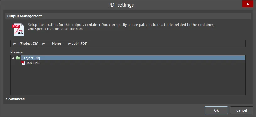
Для PDF-контейнера выходных данных появится диалог PDF Settings.

Варианты Advanced и Basic диалога PDF SettingsOptions and Controls of the PDF Settings Dialog
Управление выходными данными
Используйте эту область для задания расположения данного контейнера выходных данных. Можно указать путь, включить папку контейнера, связанную с контейнером, и задать имя файла контейнера.
- Release Managed - нажмите , чтобы открыть всплывающее окно, в котором можно настроить управление папками.
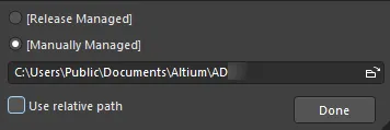
- Release Managed - выберите, чтобы сделать PDF доступным для системы выпуска PCB (PCB release system).
- Manually Managed - выберите, чтобы задать ручное управление PDF и хранение в локальной папке. По умолчанию это будет путь, указанный в поле Output Path на вкладке Options диалога Project Options.
- File Location textbox - нажмите кнопку обзора файлов, чтобы выбрать целевую папку для PDF. Этот параметр доступен только при выборе Manually Managed.
- Use relative path - включите этот параметр, чтобы использовать относительный путь в File Location textbox. Этот параметр доступен только при выборе Manually Managed.
- Done - нажмите, чтобы завершить настройку.
- None - нажмите, чтобы открыть всплывающее окно, в котором можно настроить папку контейнера для PDF.
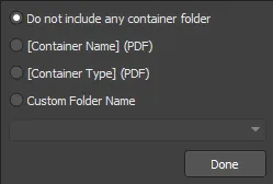
- Do not include any container folder - выберите, чтобы не включать папку контейнера.
- [Container Name] (PDF) - выберите, чтобы использовать имя контейнера в качестве имени папки контейнера.
- [Container Type] (PDF) - выберите, чтобы использовать тип контейнера в качестве типа папки контейнера.
- Custom Folder Name - выберите, чтобы настроить имя папки вручную. Нажмите стрелку раскрывающегося списка, чтобы открыть список, где можно выбрать строку именования для папки. Также можно напрямую ввести имя папки в текстовое поле.
- Done - нажмите , чтобы завершить настройку.
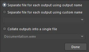
- [Filename].pdf - нажмите , чтобы открыть всплывающее окно, в котором можно настроить PDF выходные данные.
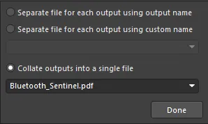
- Separate file for each output using output name - выберите, чтобы создавать отдельный файл для каждого выходного материала, используя указанное имя выходного материала.
- Separate file for each output using custom name - выберите, чтобы создавать отдельный файл для каждого выходного материала, используя пользовательское имя, заданное в текстовом поле ниже. Нажмите стрелку раскрывающегося списка, чтобы открыть список, где можно выбрать строку именования. Также можно напрямую ввести пользовательское имя в текстовое поле.
- Collate outputs into a single file - выберите, чтобы объединить выходные материалы в один файл. Нажмите стрелку раскрывающегося списка, чтобы открыть список, где можно выбрать строку именования для файла. Также можно напрямую ввести пользовательское имя в текстовое поле.
- Done - нажмите, чтобы завершить настройку.
- Preview - эта область показывает предварительный просмотр расположения PDF. По мере внесения изменений во всплывающих диалогах выше окно предварительного просмотра обновляется, чтобы вы сразу видели, как изменения влияют на структуру папок.
Расширенные команды версий
- Zoom - используйте ползунок для управления уровнем масштабирования (Far до Close) при переходе к компонентам или цепям (net).
-
Page Size And Orientation - используйте эти настройки, чтобы определить, откуда берутся размер страницы и ориентация: из диалога Page Setup dialog или из исходных документов.
- Schematic Page Size and Orientation Source - выберите Page Setup Dialog или Source Document в раскрывающемся списке, чтобы указать, какие настройки размера страницы и ориентации будут использоваться для документа схемы.
- PCB Page Size and Orientation Source - выберите Page Setup Dialog или Source Document в раскрывающемся списке, чтобы указать, какие настройки размера страницы и ориентации будут использоваться для документа PCB.
-
Output Options
- Open PDF file after export - включите, чтобы открывать PDF-файл после экспорта.
- Prompt if file already exists - включите, чтобы получать запрос, если файл уже существует.
- Generate Table of Contents - включите, чтобы сформировать оглавление в PDF-файле.
- Include Component Parameters - включите, чтобы включать параметры компонентов в PDF-файл. Параметры отображаются во всплывающем окне при щелчке по компоненту на схеме. Обратите внимание: функция всплывающего окна в Acrobat реализована с использованием JavaScript.
-
PDF/A Compliance - выберите нужный тип соответствия PDF/A в раскрывающемся списке. Если соответствие PDF/A не требуется, выберите
Disabledв раскрывающемся списке. - PDF Version - выберите нужную версию PDF в раскрывающемся списке.
-
Additional Bookmarks
-
Generate nets information - включите, чтобы добавлять информацию о цепях (net) в PDF-файл. При включении этой опции доступны следующие параметры:
- Pins - включите, чтобы добавлять в закладки Pins в PDF-файле.
- Net Labels - включите, чтобы добавлять в закладки Net Labels в PDF-файле.
- Ports - включите, чтобы добавлять в закладки Ports в PDF-файле.
- Global Bookmarks for Components and Nets - включите, чтобы создавать закладки для всех компонентов и цепей (net) в PDF-файле.
-
Generate nets information - включите, чтобы добавлять информацию о цепях (net) в PDF-файл. При включении этой опции доступны следующие параметры:
Дополнительные элементы управления
- Advanced/Basic - нажмите, чтобы переключаться между Advanced и Basic версиями диалога.
-
Для выходного контейнера Folder Structure появится диалог Folder Structure Settings.

Версии Advanced и Basic диалога Folder Structure settingsOptions and Controls of the Folder Structure Settings Dialog
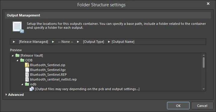
Управление выводом
Используйте эту область, чтобы настроить расположение для данного выходного контейнера. Можно указать базовый путь, добавить папку, связанную с контейнером, и задать имя файла контейнера.
- Release Managed - нажмите, чтобы открыть всплывающее окно, в котором можно настроить управление папками.
- Release Managed - выберите, чтобы сделать файл доступным для системы выпуска PCB.
- Manually Managed - выберите, чтобы файл управлялся вручную и сохранялся в локальной папке. По умолчанию это будет путь, указанный в поле Output Path на вкладке Options диалога Project Options.
- File Location textbox - нажмите значок папки, чтобы выбрать целевую папку для файла. Эта опция доступна только при выборе Manually Managed.
- Use relative path - включите эту опцию, чтобы использовать относительный путь в File Location textbox. Эта опция доступна только при выборе Manually Managed.
- Done - нажмите, чтобы завершить настройку.
- None - нажмите, чтобы открыть всплывающее окно, в котором можно настроить папку контейнера.
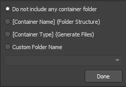
- Do not include any container folder - выберите, чтобы не добавлять папку контейнера.
- [Container Name] (Folder Structure) - выберите, чтобы использовать Folder Structure в качестве имени папки.
- [Container Type] (Generated Files) - выберите, чтобы использовать Generated Files в качестве типа папки.
- Custom Folder Name - выберите, чтобы настроить имя папки. Нажмите стрелку раскрывающегося списка, чтобы открыть список, из которого можно выбрать строку именования для папки. Также можно напрямую ввести имя папки в текстовое поле.
- Done - нажмите, чтобы завершить настройку.
- Output Type - нажмите, чтобы открыть всплывающее окно для настройки выходной папки.

- Do not include any output folder - выберите, чтобы не добавлять выходную папку.
- Output Name - выберите, чтобы использовать имя вывода в качестве имени выходной папки.
- Output Type - выберите, чтобы использовать тип вывода.
- Custom prefix_[Output Type] - выберите, чтобы указать пользовательский префикс в текстовом поле.
- Custom Folder Name - выберите, чтобы настроить имя папки. Нажмите стрелку раскрывающегося списка, чтобы открыть список, из которого можно выбрать строку именования. Также можно напрямую ввести пользовательское имя в текстовое поле.
- Done - нажмите, чтобы завершить настройку.
- Output Name - нажмите, чтобы открыть всплывающее окно, в котором можно настроить имя выходного файла.
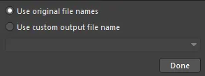
- Use standard output file name - выберите, чтобы использовать стандартное имя выходного файла.
- Use custom output file name - выберите, чтобы использовать пользовательское имя выходного файла. Нажмите стрелку раскрывающегося списка, чтобы открыть список, из которого можно выбрать строку именования. Также можно напрямую ввести пользовательское имя в текстовое поле.
- Done - нажмите, чтобы завершить настройку.
- Preview - эта область показывает предварительный просмотр структуры папок. По мере внесения изменений в указанных выше всплывающих диалогах окно предварительного просмотра обновляется, чтобы вы сразу видели, как изменения влияют на структуру папок.
Команды расширенной версии
Параметры вывода
- Open generated outputs - включите, чтобы открывать результаты вывода после генерации.
- Add generated files to project - включите, чтобы добавлять сгенерированные файлы в проект. Файлы появятся на панели Projects panel в подпапке Generated.
- Use the Output Name as the file name instead of the default - включите, чтобы использовать указанное имя вывода вместо имени по умолчанию.
- Timestamp folder - включите, чтобы создавать папку с временной меткой. Дата и время будут в том же формате, что и в системных настройках.
Параметры автозагрузки CAMtastic
Включите следующие типы вывода, если хотите автоматически загружать соответствующие результаты в CAMtastic. Включенные типы вывода будут автоматически загружаться в новый документ CAMtastic при каждом пакетном формировании.
- ODB++ Output
- Gerber Output
- NC Drill Output
- IPC-356-D Output
- Reset auto-load option after generation - включите, чтобы сбрасывать опцию автозагрузки после генерации выходных данных.
Advanced/Basic
Нажмите, чтобы переключаться между Advanced и Basic версиями диалога.
-
Для выходного контейнера Video появится диалог Video Settings.

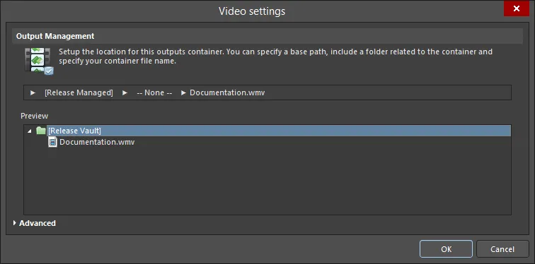
Версии Advanced и Basic диалога Video settingsOptions and Controls of the Video Settings Dialog
Управление выводом
Используйте эту область, чтобы настроить расположение для данного выходного контейнера. Можно указать базовый путь; добавить папку, связанную с контейнером, затем задать имя файла контейнера.
- Release Managed - щелкните, чтобы открыть всплывающее окно, в котором можно указать управление папками.
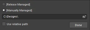
- Release Managed - выберите, чтобы сделать видео доступным для системы выпуска PCB.
- Manually Managed - выберите, чтобы задать ручное управление видео и хранение в локальной папке. По умолчанию это будет путь, указанный в поле Output Path на вкладке Options диалога Project Options.
- File location field - щелкните значок обзора, чтобы выбрать целевую папку для видео. Этот параметр доступен только когда выбрано Manually Managed .
- Use relative path - включите этот параметр, чтобы использовать относительный путь в File Location textbox. Этот параметр доступен только когда выбрано Manually Managed .
- Done - щелкните, чтобы завершить настройку.
- None - щелкните, чтобы открыть всплывающее окно, в котором можно настроить папку контейнера.
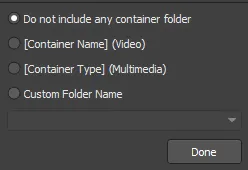
- Do not include any container folder - выберите, чтобы не включать папку контейнера.
- [Container Name] (Video) - выберите, чтобы использовать Video в качестве имени папки.
- [Container Type] (Multimedia) - выберите, чтобы использовать Multimedia в качестве типа папки.
- Custom Folder Name - выберите, чтобы настроить имя папки. Щелкните стрелку раскрывающегося списка, чтобы открыть список, в котором можно выбрать строку именования для папки. Также можно напрямую ввести имя папки в текстовое поле.
- Done - щелкните, чтобы завершить настройку.
- Output Type - щелкните, чтобы открыть всплывающее окно для настройки выходной папки.
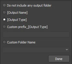
- Do not include any output folder - выберите, чтобы не включать выходную папку.
- Output Name - выберите, чтобы использовать имя вывода в качестве имени выходной папки.
- Output Type - выберите, чтобы использовать тип вывода.
- Custom prefix_[Output Type] - выберите этот параметр, чтобы указать пользовательский префикс в текстовом поле.
- Custom Folder Name - выберите, чтобы настроить имя папки. Щелкните стрелку раскрывающегося списка, чтобы открыть список, в котором можно выбрать строку именования. Также можно напрямую ввести пользовательское имя в текстовое поле.
- Done - щелкните, чтобы завершить настройку.
- Separate file for each output - щелкните, чтобы открыть всплывающее окно и указать, как настраиваются выходные файлы.
- Separate file for each output using output name - выберите, чтобы создавать отдельный файл, используя указанное имя вывода, для каждого видео.
- Separate file for each output using custom name - выберите, чтобы создавать отдельный файл, используя пользовательское имя, для каждого видео. Щелкните стрелку раскрывающегося списка, чтобы открыть список, в котором можно выбрать строку именования. Также можно напрямую ввести пользовательское имя в текстовое поле.
- Collate outputs into a single file - выберите, чтобы объединить выводы в один файл. Щелкните стрелку раскрывающегося списка, чтобы открыть список, в котором можно выбрать строку именования для файла. Также можно напрямую ввести имя файла в текстовое поле.
- Done - щелкните, чтобы завершить настройку.
Preview - эта область показывает предварительный просмотр папок. По мере внесения изменений в приведенных выше всплывающих диалогах окно предварительного просмотра обновляется, чтобы вы могли сразу видеть, как ваши изменения влияют на структуру папок.
Advanced Version Commands
Media Settings
-
Type - выберите тип носителя из раскрывающегося списка:
- Video (FFmpeg)
- Video (Windows Multimedia)
- Video (Windows Media Format)
Следующая таблица суммирует типы и форматы видео, поддерживаемые в настоящее время:
Video Type
Supported File Format(s)
Video (FFmpeg)
3GP2 (
*.3g2)
ASF (*.asf,*.wmv,*.wma)
ASF-Streaming (*.asf,*.wmv,*.wma)
AVI (*.avi)
Flash (*.swf)
FLV (*.flv)
MOV (*.mov)
MP4 (*.mp4)Video (Windows Multimedia)
Windows Video file (
*.avi)Video (Windows Media Format)
Windows Media file (
*.wmv,*.wma,*.asf)-
Format - выберите формат носителя из раскрывающегося списка. Этот параметр доступен только когда Video (FFmpeg) выбран в качестве Type.
- Video Pixels - используйте стрелки вверх и вниз (или вводите числа напрямую в текстовые поля), чтобы выбрать требуемое количество пикселей видео.
Output Options
- Open after export - включите этот параметр, чтобы открыть видео после экспорта.
- Prompt if file already exists - включите этот параметр, чтобы получать запрос, если файл уже существует.
Advanced Settings
- Video Codec - выберите параметр из раскрывающегося списка. Этот параметр доступен только когда Video (FFmpeg) или Video (Windows Media Format) выбраны в качестве Type. Следующая таблица суммирует доступные кодеки в зависимости от выбранного типа/формата видео.
Video Type/Format
Supported Codecs
FFmpeg / 3GP2
H.263 / H.263-1996
FFmpeg / ASF
MPEG-4 part 2 Microsoft variant version 2
MPEG-4 part 2 Microsoft variant version 3
raw video
Windows Media Video 7
Windows Media Video 8FFmpeg / ASF-Streaming
MPEG-4 part 2 Microsoft variant version 2
MPEG-4 part 2 Microsoft variant version 3
raw video
Windows Media Video 7
Windows Media Video 8FFmpeg / AVI
MPEG-4 part 2
MPEG-4 part 2 Microsoft variant version 2
raw videoFFmpeg / Flash
Flash Video (FLV) / Sorenson Spark / Sorenson H.263
FFmpeg / FLV
Flash Video (FLV) / Sorenson Spark / Sorenson H.263
FFmpeg / MOV
MPEG-4 part 2
FFmpeg / MP4
MPEG-4 part 2
Windows Multimedia
cvid Cinepak Codec
MSVC MS-CRAM
tscc TSCCWindows Media
Windows Media Video V7
Windows Media Video 9 Screen
Windows Media Video 9
Windows Media Video V8
Windows Media Video 9 Advanced Profile- Compression - выберите требуемую настройку сжатия из раскрывающегося списка. Этот параметр доступен только когда Video (Windows Multimedia) выбрано в качестве Type.
- Pixel Format - используйте раскрывающийся список, чтобы выбрать требуемый формат пикселей для видео. Этот параметр доступен только когда Video (Windows Multimedia) выбрано в качестве Type.
- Frames Per Second - введите требуемое количество кадров в секунду для видео. Значение по умолчанию — 25.
- Quality - используйте ползунок для задания качества видео — от минимального до максимального.
Advanced/Basic
Щелкните, чтобы переключаться между версиями диалога Advanced и Basic .
Диалог Settings изначально открывается в режиме Basic для настройки местоположения вывода, то есть где будет создан контейнер. Чтобы получить доступ к дополнительным, более расширенным параметрам, связанным с формированием вывода в контейнер, нажмите кнопку Advanced в нижней части диалога.

Откройте диалог Settings для контейнера, чтобы настроить его требуемым образом. В режиме Basic используйте диалог, чтобы определить местоположение вывода для контейнера.

Более детальные параметры доступны, когда диалог находится в режиме Advanced .
Output Location
Местоположение вывода — где будет создан контейнер — задается в области Output Management диалога настроек контейнера. Местоположение состоит из нескольких этапов, при этом каждый этап задается через соответствующее всплывающее окно, которое открывается щелчком по этому этапу.
- Base Path – этот этап используется для определения «корневого» пути контейнера вывода.

Параметры для определения базового пути местоположения вывода.
По умолчанию установлено значение [Release Managed], что означает, что процесс Board Design Release, выполняемый в Project Releaser, будет автоматически обрабатывать базовый путь.
Локальный путь вывода можно задать, переключив этот этап на [Manually Managed] и указав путь соответствующим образом (его можно сделать относительным по отношению к проекту разработки).
- Container Type Folder – этот этап используется для определения подпапки на основе типа создаваемого медиаконтейнера. Использование этой дополнительной «зонтичной» папки полностью необязательно. Если она используется, ей можно либо дать имя системой (используя имя или тип контейнера), либо при необходимости задать пользовательское имя.

Параметры для определения подпапки контейнера для местоположения вывода.
- Output Folder / Output Filename– функция этого этапа зависит от типа выходного контейнера, для которого задаётся расположение выходных данных. Для типов контейнеров PDF или Video на этом этапе требуется ввести желаемое имя файла. По умолчанию несколько выходных данных, сформированных в контейнер, будут объединены в один файл, однако при необходимости можно создать отдельный файл для каждого выходного результата.
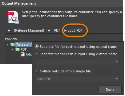

Параметры для задания имени файла и необязательной подпапки.
Для типа контейнера Folder Structure этот этап используется для указания папки для каждого сгенерированного типа выходных данных. Аналогично, папка может именоваться автоматически на основе имени или типа выхода либо может быть настроена с заданным префиксом. По мере внесения изменений на любом из этапов в расположении выходных данных окно предварительного просмотра диалога будет динамически обновляться, позволяя быстро подобрать предпочтительную структуру выходных папок. Для каждого определённого контейнера пути — как серверные (Release Managed), так и локальные (Manually Managed) — отображаются для быстрого просмотра в основной области Output Containers файла OutJob.
Правила конкатенации элементов
Пользовательское имя выходного файла формируется путём конкатенации (соединения) требуемых элементов. Процесс конкатенации подчиняется следующим правилам:
| Элемент | Функция | Пример | Возвращает |
|---|---|---|---|
| = (равно) | Указывает, что следующая строка является выражением, которое необходимо интерпретировать. | =ProjectName | DB31 для примера проекта с именем DB31.PrjPcb |
| + (плюс) | Используется для конкатенации элементов, требуемых в имени выходного файла. | =ProjectName + '-' + ProjectRevision + '.PDF' | DB31-07.PDF для примера проекта с именем DB31.PrjPcb |
| ' ' (одинарные кавычки) | Используется для вставки фиксированной строки в любом месте имени выходного файла. Недопустимые символы перечислены ниже. | ='AcmeEngineering' +_+ ProjectName + '.PDF' | AcmeEngineering_DB31.PDF для примера проекта с именем DB31.PrjPcb |
Недопустимые символы и синтаксические ошибки
Следующие символы не допускаются в пользовательских именах выходных файлов:
< > : " \ | ? *
Если в выражении есть синтаксическая ошибка, например несбалансированная кавычка, как =ProjectName+.PDF' вместо =ProjectName+'.PDF', это даст результат #NAME. Увидев это, внимательно проверьте, не отсутствуют ли кавычки и нет ли недопустимых или ошибочно введённых специальных строк.
Поддерживаемые параметры
Поддерживаются пользовательские параметры уровня проекта и параметры вариантов (variant). Параметры проекта задаются на вкладке Parameters диалога Project Options (Project » Project Options). Параметры вариантов можно определить для каждого варианта в диалоге Variant Management dialog или в Variant Manager (Project » Variants).
Имена параметров не могут содержать пробелы. Например, параметр PartNumber использовать можно, однако параметр Part Number — нельзя.
Поддерживаемые специальные строки
Special Strings — термин, используемый в Altium Designer для обозначения интерпретируемых строк. Большинство таких строк можно интерпретировать на экране, разместив текстовую строку со значением =SpecialStringName, например =CurrentDate. При генерации выходных данных они интерпретируются всегда.
В настоящее время поддерживаются следующие Special Strings, которые можно использовать в именах выходных файлов:
| Special String | Возвращает |
|---|---|
| CurrentDate | Текущую дату, полученную из операционной системы, в формате ISO 8601 yyyy-mm-dd. Пример: 2016-01-25 |
| CurrentTime | Текущее время, полученное из операционной системы, в формате hh_mm. Пример: 14_55. |
| DataSource | Источник данных (Data Source), используемый для этого выхода в файле Output Job. |
| OutputName | Пользовательское имя этого выхода в файле Output Job. Работает только когда в настройках именования выходного файла выбрана опция Separate File for Each Output . |
| ProjectName | Отображает фактическое имя проекта без расширения. |
| VariantName | Имя варианта сборки, определённого для этого проекта в Variant Management dialog или в Variant Manager. Используемое значение зависит от варианта, выбранного в Output Job для того выхода, для которого задаётся имя файла. |
| ProjectParameterName | Значение параметра проекта с именем <ProjectParameterName>. |
| VariantParameterName | Значение параметра варианта с именем <VariantParameterName>. |
Именование объединённых выходных файлов
Для объединённых (collated) выходных файлов можно использовать только те специальные строки, которые не привязаны к конкретному выходу. Например, OutputName нельзя использовать для объединённого выходного файла, поскольку он относится к конкретному выходу в файле Output Job. VariantName и DataSource также использовать нельзя. Использование одной из этих специальных строк в объединённом выходном файле приведёт к тому, что фактическая строка будет использована как имя файла.
Если выражение не удаётся проанализировать, сохраните, затем закройте и снова откройте файл Output Job, чтобы обновить механизм анализа выражений.
Hard Copy — задания печати
Некоторые выходные данные, включая печать схем (Schematic Prints), сборочные чертежи (Assembly Drawings) и BOM, также можно отправлять напрямую на печатающее устройство как Hard Copy. Чтобы определить, как обрабатывается такая печать, добавляется и настраивается Print Job.
Новый OutJob по умолчанию содержит одно задание печати (Print Job) с именем Print Job и нацелено на принтер по умолчанию, связанный с компьютером, на котором запущен экземпляр Altium Designer. Любое количество дополнительных заданий печати можно добавить щелчком по тексту [Add New Print Job] или из подменю Edit » Add Print Job ; их имена можно редактировать для удобной идентификации (например, по имени печатающего устройства, с которым связано задание).

Задания печати обрабатывают выходные данные, ориентированные на печать, или «Hard Copy».
Настройка задания печати
Щелчок по Print Job открывает доступ к дополнительным элементам управления, включая возможность настройки задания. Для этого нажмите ссылку Change, чтобы открыть диалог Printer Configuration, связанный с данным заданием. Доступ к диалогу Printer Configuration также можно получить, дважды щёлкнув запись Print Job или выделив её, щёлкнув правой кнопкой и выбрав команду Properties .

Откройте диалог Printer Configuration, чтобы настроить Print Job требуемым образом.
В диалоге Printer Configuration нажмите кнопку Properties , чтобы открыть стандартный диалог Properties для целевого принтера. В этом диалоге задайте источник бумаги и макет, а также получите доступ к расширенным настройкам свойств принтера.
Связывание выходов с выходными контейнерами и заданиями печати
После добавления и настройки выходов OutJob, а также определения требуемых Output Containers и Print Jobs, их необходимо сопоставить, то есть указать, какие выходы должны генерироваться с использованием какого контейнера и/или задания печати.
У каждого выхода есть связанное поле Enabled . Это поле управляет тем, включён ли конкретный выход (опция включена) или исключён (опция выключена) из выбранного Output Container или Print Job.
Также можно быстро включить/выключить все выбранные выходы или все выходы в активной категории, подключая их к / отключая их от текущего выбранного выходного контейнера или задания печати, щёлкнув правой кнопкой по выходу в выделении или в нужной категории выходов и выбрав Enable Selected (сочетание: Ctrl+Num +)/Disable Selected (сочетание: Ctrl+Num -), Enable All/Disable All команду в контекстном меню.
После включения зелёная линия соединит выход с выбранным контейнером/заданием печати. Один и тот же выход может быть включён во множество выходных носителей: например, BOM можно сгенерировать и вывести как PDF, как отдельный файл или отправить на принтер для немедленного получения hard copy.

Выберите контейнер или задание печати, затем включите выходы, которые должны генерироваться с использованием этого контейнера или задания печати.
На изображении выше три выхода были включены для генерации с использованием PDF-ориентированного Output Container с именем PDF. Обратите внимание, что выходы Test Point Report, Pick and Place и Gerber Files не имеют поля Enabled , поскольку эти типы выходных данных нельзя записать в PDF-файл.
По мере включения выходов им присваиваются последовательные номера. Этот порядок используется для определения последовательности, в которой выходы генерируются. Если создаётся один PDF, включающий несколько разных выходов, этот порядок определяет последовательное содержимое этих выходов внутри данного PDF.
Если выход удаляется из контейнера или задания печати, номера соответствующим образом перенумеровываются. Чтобы изменить порядок включённых выходов, либо дважды щёлкните по номеру в поле Enabled у выхода и используйте доступный элемент управления, чтобы задать нужный номер, либо заново выберите каждый выход в требуемом порядке.
При использовании команд Enable Selected/Disable Selected, Enable All/Disable All может быть полезно сначала отсортировать порядок, поскольку последовательность генерации выходов назначается по порядку выходов. Это можно сделать быстро и эффективно, щёлкнув по выходу и перетащив его на новое место внутри его категории.
Почему моя ссылка Output to Container красная?
Когда целевое назначение для применимого печатного (print-based) вывода меняется с PDF-контейнера вывода на физический принтер (задание печати), вполне возможно, что размер бумаги, заданный для генератора через соответствующее диалоговое окно свойств (правый клик, Page Setup), не поддерживается выбранным носителем. В этом случае соединительная стрелка от генератора к носителю окрашивается в красный цвет, когда вывод включен. В таком состоянии предварительный просмотр/печать будут недоступны. Вы можете либо изменить размер бумаги для генератора вывода и тем самым вернуть соединительную стрелку в зеленое состояние, прежде чем соответствующий вывод сможет быть успешно сгенерирован. Либо просто сменить целевой носитель на тот, который поддерживает выбранный размер бумаги. Если обнаружено несоответствие размеров бумаги и вы решите изменить размер бумаги для настроенного вывода, использование команды Page Setup для этого вывода вызовет информационное окно. Оно предупредит о проблеме и сообщит, что размер бумаги восстановлен к значению по умолчанию. Это означает, что выпадающий список размеров бумаги в диалоге конфигуратора будет заново заполнен стандартным набором размеров, поддерживаемых целевым принтером.

Красная связь указывает на несоответствие между настройками страницы и свойствами страницы, доступными в выбранном контейнере.
Выбор варианта
Требования к продукту могут обусловливать необходимость выпускать несколько похожих печатных плат, которые лишь немного отличаются от базового проекта. Например, стандартная и расширенная версии коммерческого электронного изделия могут различаться по функциональности: в стандартной версии используется лишь часть компонентов, применяемых в расширенной.
На уровне проекта Altium Designer позволяет определить одну или несколько вариаций конструкции платы с помощью функции Variants. Вариант — это просто альтернативно собранная «версия» исходного проекта платы.
Варианты обычно определяют применимые выходные данные для сборки — в этом и заключается суть Assembly Variant, при этом меняется только собранная плата (например, какие компоненты установлены, а какие — нет). Однако Altium Designer также позволяет вариантам управлять некоторыми выходными данными для изготовления, давая возможность изменять комментарий компонента в проекте и передавать это изменение в такие выходные данные, как Gerber, ODB++ файлы, Composite Drill Drawings, Drill Drawing/Guides и Final Artwork Prints.
Внутри OutJob у вас есть полный контроль над тем, что используется для формирования заданных выходных данных — либо базовый (без вариаций) проект, либо выбранный определенный вариант этого проекта.
Если выходные данные должны генерироваться для конкретного варианта, этот вариант необходимо указать в рамках конфигурации OutJob. Либо выберите вариант для каждого применимого вывода, либо выберите один вариант, который будет применен ко всем применимым выходным данным в файле. Эта «область применения варианта» (variant scope) задается с помощью параметров Variant Choice в верхней части файла Output Job.

Параметры Variant Choice определяют, на каком уровне используются варианты при формировании настроенных выходных данных файла Output Job.
-
Choose a single variant for the whole outputjob file – при включении этого параметра выберите один вариант, который будет использоваться для всех применимых выходных данных в файле Output Job. Укажите вариант в выпадающем поле справа. В списке отображаются все определенные варианты активного проекта, а также пункт
[No Variations]. -
Choose a different variant for each output – при включении этого параметра в область Outputs файла OutJob будет добавлен столбец Variant . Используйте это поле, чтобы указать, какой вариант применять для каждого отдельного вывода. Как и ранее, выпадающий список содержит все определенные варианты активного проекта, а также пункт
[No Variations]. При такой настройке области применения можно назначать разные варианты для формирования разных выходных данных.
Чтобы формировать выходные данные на основе базового (без вариаций) проекта, используйте пункт [No Variations].
При задании использования вариантов на уровне отдельных выходных данных, если выбранный вариант не допускает вариации выходных данных для изготовления и этот вариант указан для вывода, относящегося к изготовлению, запись варианта в OutJob будет отображаться красным цветом, а при наведении будет показана подсказка, указывающая на ситуацию. Генерация вывода с выбранным вариантом будет выполняться так, как если бы был выбран параметр [No Variations]. Иными словами, в качестве источника вывода будет использован базовый (без вариаций) проект.
Генерация выходных данных
Настроенные выходные данные в OutJob можно сгенерировать:
- Непосредственно из OutJob.
- Из Project Releaser.
Из Output Containers
Выбор Output Container предоставляет доступ к элементу управления Generate content. Этот элемент становится доступным после назначения в контейнер хотя бы одного вывода.

Сгенерировать содержимое для выбранного Output Container.
Нажмите этот элемент управления, чтобы последовательно сгенерировать в контейнер каждый вывод, включенный для генерации. Либо, при выбранном контейнере, используйте один из следующих способов генерации содержимого:
- Нажмите клавишу F9.
- Щелкните правой кнопкой мыши и выберите команду Generate в контекстном меню (Run команда для контейнера Folder Structure).
- Используйте команду Tools » Generate (типы контейнеров PDF и Video) или команду Tools » Run (тип контейнера Folder Structure).
-
Нажмите кнопку
 (тип контейнера PDF),
  (тип контейнера Video) или
  (тип контейнера Folder Structure) на панели инструментов Job Manager Toolbar.
Ход выполнения можно отслеживать в строке состояния. Сгенерированный вывод будет записан в расположение, заданное в настройках контейнера вывода. Эти настройки также определяют, будет ли вывод открыт и/или добавлен в панель Projects. Сгенерированный вывод будет открыт, если соответствующая опция включена в расширенных параметрах контейнера.
Процесса пакетной генерации для нескольких Output Container не предусмотрено; будут сгенерированы только те выходные данные, которые назначены текущему выбранному Output Container. Чтобы сгенерировать все выходные данные, по отдельности выберите каждый определенный Output Container и выполните генерацию его содержимого.
Публикация сгенерированного содержимого
Второй элемент управления — Generate and publish — позволяет сгенерировать выходные данные, назначенные выбранному Output Container, и также опубликовать этот вывод в заданное Publishing Destination.
Publishing Destinations позволяют публиковать данные в хранилище, например Box.net, Amazon S3, FTP-сервер или папку в общей сетевой локации. С точки зрения распространения и совместной работы это дает непревзойденное преимущество в современном мире, где участники общей «команды продукта» — команда разработки, команда производства и все остальные, вовлеченные в процесс превращения идеи в реальность, — часто распределены по всему миру. Все стороны получают общий (и контролируемый) доступ для просмотра, обсуждения и использования данных.
Чтобы опубликовать, нажмите команду, затем выберите пункт из списка уже определенных назначений в появившемся всплывающем меню. Сначала вывод будет сгенерирован в локальный путь назначения, затем опубликован. В процессе публикации появится запрос на выбор папки (внутри целевого Publishing Destination), в которой следует сохранить вывод. Можно выбрать существующую папку, указать новую или принять папку по умолчанию — с именем, сформированным по типу содержимого контейнера и отметке даты-времени (например, PDFs - 10-24-2011 11-32-33 AM).
Используйте команду Manage Publishing в меню, чтобы открыть страницу Data Management – Publishing Destinations диалога Preferences . Здесь можно определить новые назначения или изменить подключения к существующим.

Publishing Destinations задаются в настройках Data Management.
Для выпущенных данных, сгенерированных из проекта платы, сервер поддерживает возможность публиковать эти выпущенные документы, т.е. сгенерированный вывод из файлов Output Job, назначенных конфигурации выпуска проекта, для любой ревизии элемента (Item Revision) в заданное Publishing Destination.
Публикация данных напрямую из OutJob помещает копию сгенерированных файлов в указанную подпапку целевого расположения. Для обеспечения высокой целостности и удобства ведения надежного аудиторского следа сгенерированные данные следует публиковать после релиза — в ревизию целевого элемента (Item) на сервере. Такой вывод помечается (в имени файла) Item и Revision, что позволяет всем участникам сразу видеть, какой вывод относится к какой ревизии элемента, который будет изготавливаться (печатная плата без монтажа или плата в сборе).
Из заданий печати
Выбор задания печати открывает доступ к элементам управления «Предпросмотр» и «Печать». Эти элементы управления будут активны при условии, что для данного задания назначен хотя бы один вывод.

Элементы управления «Предпросмотр» и «Печать» для выбранного задания печати.
Предпросмотр печати
Нажмите Preview , чтобы загрузить назначенные выводы для задания печати в окно предпросмотра. Либо, при выбранном задании, используйте один из следующих способов для открытия предпросмотра печати:
- Щелкните правой кнопкой мыши и выберите Print Preview в контекстном меню.
- Используйте команду Tools » Print Preview.
-
Нажмите кнопку
 на панели инструментов Job Manager Toolbar.
- Нажмите кнопку Preview в диалоге Page Setup (File » Page Setup) для выбранного (активного) вывода. Обратите внимание: при этом будут загружены только страницы для данного конкретного вывода, а не все страницы всех выводов, назначенных заданию печати.
Исходные документы будут загружаться последовательно и в соответствии с параметрами, заданными в связанном диалоге Page Setup.
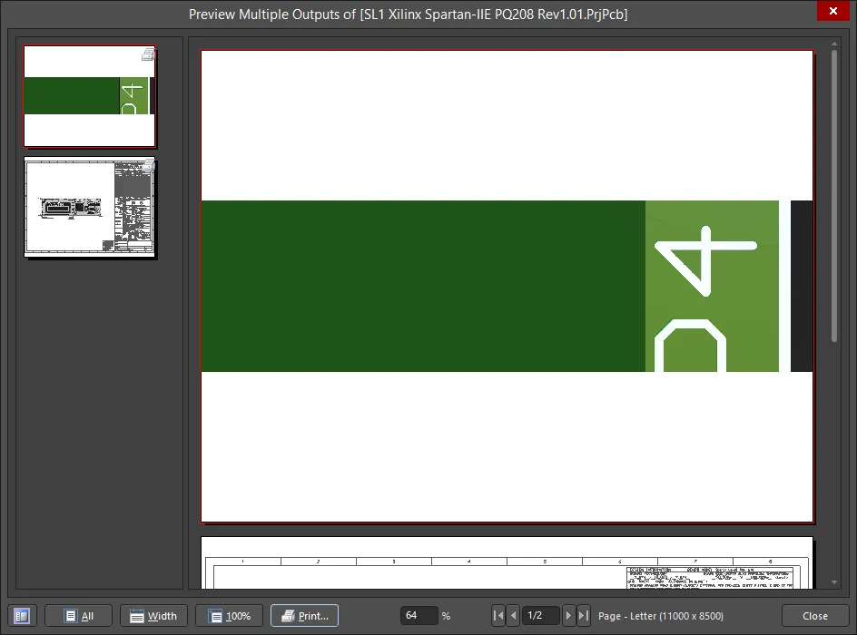
В нижней части окна предварительного просмотра отчета и в его контекстном меню (по правому щелчку) доступны элементы управления для изменения вида, доступа к диалогам настройки принтера, печати, копирования страницы в буфер обмена Windows и экспорта активной страницы в формат Windows Metafile.
Печать
Нажмите Print , чтобы отправить вывод(ы) напрямую на выбранное печатающее устройство. Либо назначенные вывод(ы) можно распечатать одним из следующих способов:
- Нажмите клавишу F9 .
- Щелкните правой кнопкой мыши и выберите команду Print в контекстном меню.
- Используйте команду Tools » Print.
- Нажмите кнопку Print в диалоге Page Setup для выбранного (активного) вывода. Обратите внимание: при этом будут распечатаны только страницы для данного конкретного вывода, а не все страницы всех выводов, назначенных заданию печати.
- Нажмите кнопку Print в диалоге Print Preview.
-
Нажмите кнопку
 на панели инструментов Job Manager Toolbar.
Элемент управления Print и первые три способа из списка выше обеспечивают прямую печать. Два последних способа — это косвенная печать через диалог Printer Configuration.
Из Project Releaser
Выводы, определенные в одном или нескольких файлах Output Job, назначенных конфигурации PCB-проекта, генерируются при выпуске (release) этой конфигурации. Генерация выполняется как часть процесса релиза с высокой целостностью, при этом данные релиза сохраняются в новой, запланированной ревизии целевого Item на сервере. Для этого используется интерфейс Project Releaser .
Доступ к Project Releaser можно получить следующими способами:
- Выберите команду Project » Project Releaser в главном меню (при открытом исходном документе нужного проекта как активном документе).
- Щелкните правой кнопкой мыши по записи нужного проекта в панели Projects panel, затем выберите команду Project Releaser в контекстном меню.
Если перед запуском Project Releaser выводы not не были определены, это можно сделать вместо этого в рамках процесса релиза.

Пример списка выводов, которые будут сгенерированы для выбранной конфигурации.
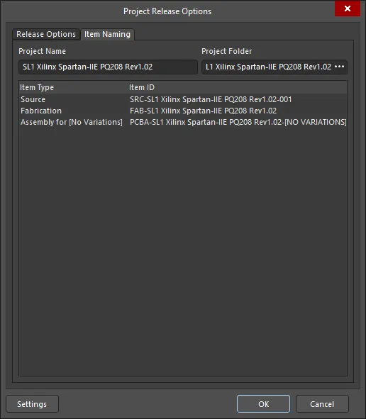
В Project Releaser нажмите кнопку Options (в левом нижнем углу), чтобы открыть диалог Project Release Options dialog. Этот диалог используется для назначения соответствующих OutJob и определения того, как именуются целевые элементы данных на сервере (чьи ревизии получают сгенерированные данные) при выпуске проекта. Вкладка Release Options содержит несколько параметров в области Output Jobs для включения нужных выходных данных.

Вкладка Release Options диалога Project Release Options.
Если в вашем проекте сейчас нет связанных файлов Output Job, Project Releaser обнаружит это и предложит добавить наборы по умолчанию. Если вы согласитесь, будет создано следующее:
-
Fabrication.OutJob - со следующими определенными выводами:
- Documentation Outputs: PCB Prints
- Fabrication Outputs: Gerber, NC Drill, and IPC-2581
- Validation Outputs: Design Rules Check, Footprint Comparison Report
- Export Outputs: Save As/Export PCB (in ASCII format)
-
Assembly.OutJob - со следующими определенными выводами:
-
Documentation Outputs: PCB 3D Print, Schematic Prints, Composite Drawing
-
Assembly Outputs: Pick and Place Report, Assembly Drawings, Test Point Report
-
Report Outputs: Bill of Materials, Component Cross Reference, GOST BOM
-
- Export Outputs: Export STEP
Дополнительные сведения о процессе релиза см. на странице Design Project Release.
 Локализовано с помощью ИИ