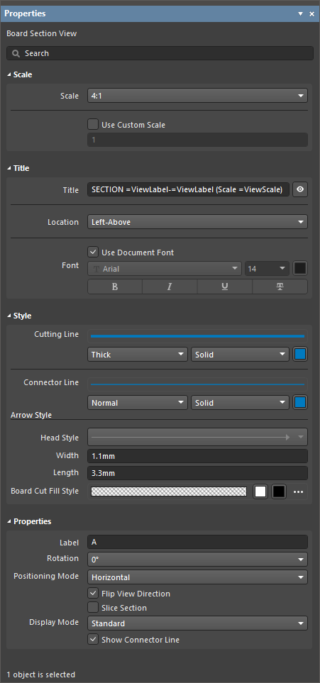
Title フィールドには、固定テキストと、特殊文字列の形式で任意のパラメータを含めることができます。タイトルにパラメータを含めるには =<ParameterName> 構文を使用します。含めたパラメータの値は、図面シート上のタイトルに表示されます。
スタイル
Cutting Line
ドロップダウンを使用して、ビューの矢印付きインジケータ線を描画する線幅と線種を選択します。利用可能なオプションは、デザインスペースで何も選択されていないときの Line Styles領域にある Properties パネルで定義されます。詳細は Setting Up a Draftsman Document ページを参照してください。 関連するカラーボタンで線の色を指定します。
Connector Line
ドロップダウンを使用して、矢印付き断面インジケータの間にある(基板アセンブリビューを横切る)カットラインを描画する線幅と線種を選択します。利用可能なオプションは、デザインスペースで何も選択されていないときの Line Styles 領域にある Properties パネルで定義されます。詳細は Setting Up a Draftsman Document ページを参照してください。 関連するカラーボタンで 線の色を指定します。
Arrow Style
提供されているオプションを使用して、断面インジケータを設定します。
Head Style – ドロップダウンメニューから、プリセットの断面インジケータスタイル(ヘッダー)を選択します。矢印に設定すると、断面の表示方向を示します。
ドロップダウンを使用して、リーダーラベル線(Display LineオプションがWith Leaderに設定されている場合)を描画する線の太さとパターン、またはソース外形とビュー本体を接続する線(Display LineオプションがConnectedに設定されている場合)を描画する線の太さとパターンを選択します。使用可能なオプションは、デザインスペースで何も選択されていないときにPropertiesパネルのLine Styles領域で定義されます。詳細は、Setting Up a Draftsman Document ページを参照してください。関連するカラーボタンを使用して線の色を指定します。
Source Border Line
ドロップダウンを使用して、ビューのソース領域外形を描画する線の太さとパターンを選択します。使用可能なオプションは、デザインスペースで何も選択されていないときにPropertiesパネルのLine Styles領域で定義されます。詳細は、Setting Up a Draftsman Document ページを参照してください。関連するカラーボタンを使用して線の色を指定します。
Detail Border Line
ドロップダウンを使用して、ビューの拡大領域外形を描画する線の太さとパターンを選択します。使用可能なオプションは、デザインスペースで何も選択されていないときにPropertiesパネルのLine Styles領域で定義されます。詳細は、Setting Up a Draftsman Document ページを参照してください。関連するカラーボタンを使用して線の色を指定します。
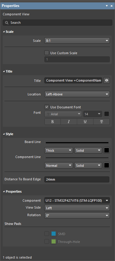
View SideがTop以外の値に設定されている場合に基板線を描画するための線の太さとパターンを、ドロップダウンで選択します。使用可能なオプションは、デザインスペースで何も選択されていないときにPropertiesパネルのLine Styles領域で定義されます。詳細は、Setting Up a Draftsman Document ページを参照してください。関連するカラーボタンを使用して線の色を指定します。
Component Line
ドロップダウンを使用して、ビュー内のコンポーネント形状を描画する線の太さとパターンを選択します。使用可能なオプションは、デザインスペースで何も選択されていないときにPropertiesパネルのLine Styles領域で定義されます。詳細は、Setting Up a Draftsman Document ページを参照してください。関連するカラーボタンを使用して線の色を指定します。
Title フィールドには、固定テキストと、特殊文字列の形式で任意のパラメータを含めることができます。=<ParameterName> 構文を使用して、タイトルにパラメータを含めます。含めたパラメータの値は、図面シート上のタイトルに表示されます。
スタイル
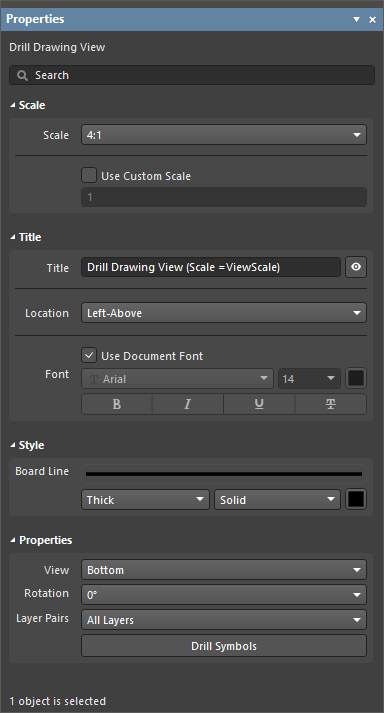
Board Line
ドロップダウンを使用して、ビューの枠線/外形をレンダリングする線の太さとパターンを選択します。利用可能なオプションは、デザインスペースで何も選択されていないときに Properties パネルの Line Styles 領域で定義されます。詳細は Setting Up a Draftsman Document ページを参照してください。関連するカラーボタンを使用して線の色を指定します。
図面ビューに表示するPCBドリル・レイヤーペアの穴を選択します。ドロップダウンメニューを使用して、ソース基板設計で利用可能なレイヤーペア(PCBエディタの Layer Stack Manager で表示・編集可能)から選択します。すべての基板設計には Top Layer から Bottom Layer のペアがあり、その他のペアは、内層/プレーン層など別のレイヤー間、または別レイヤーまで貫通するビア穴を表します。詳細は Blind, Buried & Micro Via Definition ページを参照してください。
Counterhole Bottom および Counterhole Top オプションは、PCBドキュメントに、PCBの対応する面でカウンターホール機能が有効なパッドオブジェクトが含まれている場合にのみ使用できます。詳細は Working with Pads & Vias ページを参照してください。
カウンターホールは、Counterhole Bottom および Counterhole Top 以外のレイヤーペアからは除外される点に注意してください。カウンターホールは All Layers レイヤーペアからも除外されます。
ボタンをクリックして Drill Symbol Configurations ダイアログを開きます。このダイアログでは、すべてのドリル穴データを表形式で表示し、選択可能なパラメータ(列データ)に基づいて穴スタイルをグループ化し、標準シンボルを割り当てます。また、各穴シンボルのスタイルとサイズを設定できます。
これは、ドリルテーブル用に Properties パネルから起動されるものと同じダイアログですが、この場合は利用可能なすべての列が表示されます。2つの Drill Symbol Configuration ダイアログのバージョンは同一ソースに基づくため、相互に連動する点に注意してください。ダイアログの詳細は Drill Table ページを参照してください。
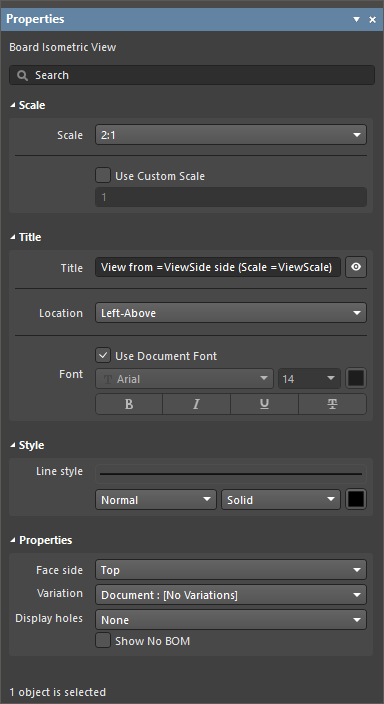
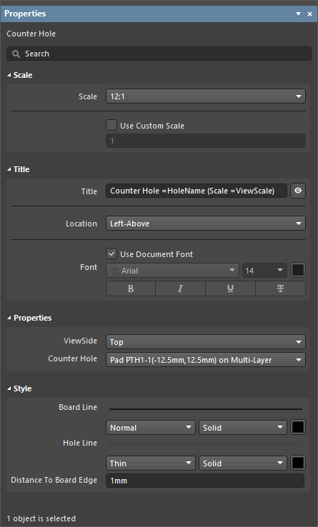
Title フィールドには、固定テキストと、特殊文字列の形式で任意のパラメータを含めることができます。=<ParameterName> 構文を使用して、タイトルにパラメータを含めます。含めたパラメータの値は、図面シート上のタイトルに表示されます。
スタイル
Line Style
ドロップダウンを使用して、ビューの基板外形およびコンポーネント形状をレンダリングする線の太さとパターンを選択します。利用可能なオプションは、デザインスペースで何も選択されていないときに Properties パネルの Line Styles 領域で定義されます。詳細は Setting Up a Draftsman Document ページを参照してください。関連するカラーボタンを使用して線の色を指定します。
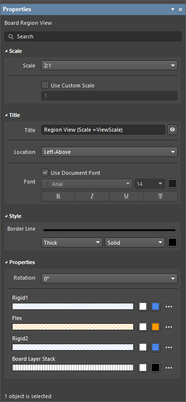
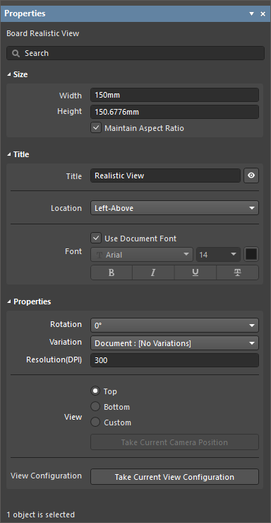
Title フィールドには、固定テキストと、特殊文字列の形式で任意のパラメータを含めることができます。タイトルにパラメータを含めるには、=<ParameterName> 構文を使用します。含めたパラメータの値は、図面シート上のタイトルに表示されます。
スタイル
Border Style
ドロップダウンを使用して、ビューの基板外形を描画するための線の太さとパターンを選択します。使用可能なオプションは、デザインスペースで何も選択されていないときに Properties パネルの Line Styles 領域で定義されています。詳細は Setting Up a Draftsman Document ページを参照してください。関連するカラーボタンを使用して線の色を指定します。
ドロップダウンを使用して、ビューの基板線を描画するための線の太さとパターンを選択します(ViewSide が Left に設定されている場合に適用)。使用可能なオプションは、デザインスペースで何も選択されていないときに Properties パネルの Line Styles 領域で定義されています。詳細は Setting Up a Draftsman Document ページを参照してください。関連するカラーボタンを使用して線の色を指定します。
Hole Line
ドロップダウンを使用して、ビューの穴形状を描画するための線の太さとパターンを選択します。使用可能なオプションは、デザインスペースで何も選択されていないときに Properties パネルの Line Styles 領域で定義されています。詳細は Setting Up a Draftsman Document ページを参照してください。関連するカラーボタンを使用して線の色を指定します。
Distance To Board Edge
ViewSide が Left に設定されている場合、穴ビューから基板エッジまでの距離を指定します。
ドロップダウンを使用して、ビューの外形線をレンダリングするための線幅とパターンを選択します。利用可能なオプションは、デザインスペースで何も選択されていないときに Properties パネルの Line Styles 領域で定義されています。詳細は Setting Up a Draftsman Document ページを参照してください。関連するカラーボタンを使用して線の色を指定します。
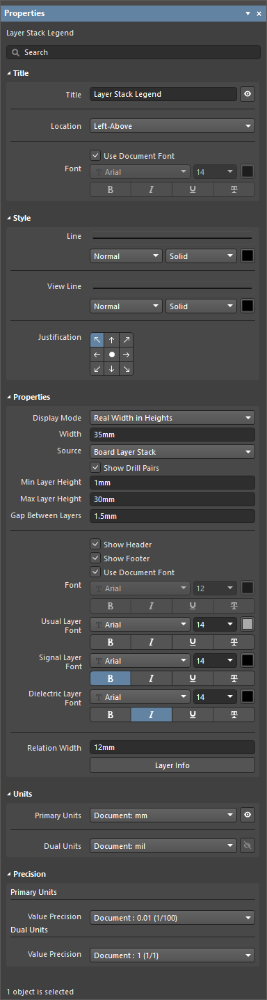
Title フィールドには、固定テキストおよび特別な文字列形式の任意のパラメータを含めることができます。タイトルにパラメータを含めるには =<ParameterName> 構文を使用します。含めたパラメータの値は、図面シート上のタイトルに表示されます。
Style
Line
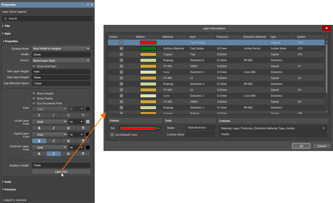
ドロップダウンを使用して、各レイヤー表現と対応する仕様テーブル行の間に描画される線の線幅とパターンを選択します。利用可能なオプションは、デザインスペースで何も選択されていないときに Properties パネルの Line Styles 領域で定義されています。詳細は Setting Up a Draftsman Document ページを参照してください。関連するカラーボタンを使用して線の色を指定します。
View Line
ドロップダウンを使用して、ビューのレイヤー表現の外形をレンダリングするための線幅とパターンを選択します。利用可能なオプションは、デザインスペースで何も選択されていないときに Properties パネルの Line Styles 領域で定義されています。詳細は Setting Up a Draftsman Document ページを参照してください。関連するカラーボタンを使用して線の色を指定します。
Justification
サイズが更新された場合に、ビューの位置を変更する基準点を選択します。
Properties
Display Mode
Min Layer Height および Max Layer Height の設定制約内で、ビューのグラフィックにおける各レイヤー表現のレンダリング高さを決定します。ドロップダウンからレイヤー高さのオプションを選択します。
Default – すべてのレイヤーを同一の標準高さでレンダリングします。
Real Width in Heights – 各ボードレイヤーの実際の厚みに比例した高さでレイヤーをレンダリングします。
任意のレイヤーの最小レンダリング高さです。この設定がグラフィックに影響するのは、Display Mode オプションが Real Width in Heights に設定されている場合のみです。
Max Layer Height
任意のレイヤーの最大レンダリング高さです。この設定がグラフィックに影響するのは、Display Mode オプションが Real Width in Heights に設定されている場合のみです。
Gap Between Layers
レイヤーグラフィック間に必要な空きスペース量を設定します。
Show Header
ビューのテーブル内の列ヘッダーキャプションを有効/無効にします。
Show Footer
ビューのテーブル下部に表示される基板総厚の読み取り表示を有効/無効にします。
Font
ビューのテーブルで使用するヘッダーおよびフッターのフォントを設定します。
Use Document Font オプションが有効な場合、使用されるフォントは document options で定義されたものになります(デザインスペースで何も選択されていないときの Properties パネルの General タブの General 領域にある Document Font エントリ)。
Use Document Font オプションが無効な場合、用意されたオプションを使用して、希望するフォント種類、サイズ、色、文字属性を選択します。
Document : <Units> オプションが Primary Units として選択されている場合、ドキュメントで指定された主単位がビューに適用されます。ドキュメントレベルの主単位は、デザインスペースで何も選択されていないときに Properties パネルの General タブの Units 領域にある Primary Units ドロップダウンで選択します。詳細は Setting Up a Draftsman Document ページを参照してください。
Document : <Units> オプションが Dual Units として選択されている場合、ドキュメントで指定されたデュアル単位がビューに適用されます。ドキュメントレベルのデュアル単位は、デザインスペースで何も選択されていないときに Properties パネルの General タブの Units 領域にある Dual Units ドロップダウンで選択します。詳細は Setting Up a Draftsman Document ページを参照してください。
Precision
Primary Units
Value Precision ドロップダウンメニューを使用して、主レイヤー寸法テーブル項目の精度定義(小数点以下最大 5 桁、最終桁は丸め)を設定します。
Dual Units
Value Precision ドロップダウンメニューを使用して、(有効な場合)デュアルレイヤー寸法テーブル項目の精度定義(小数点以下最大 5 桁、最終桁は丸め)を設定します。


 )。
)。
 )。
)。 )。
)。 )にアクセスします。
")
 に変わります)、次に
  に変わります)、次に
 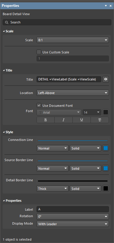 )でビューを選択すると、
 )を選択します。
 )を定義するプロパティ設定も提供されます。
 )。それぞれ有効にすると、ボンドワイヤ投影とダイパッドが描画されます。関連するカラーボタンを選択して、オブジェクト表示色を指定します。

 )。
)。

 )。
)。

 )。
)。
 )にアクセスします。

 )。
)。
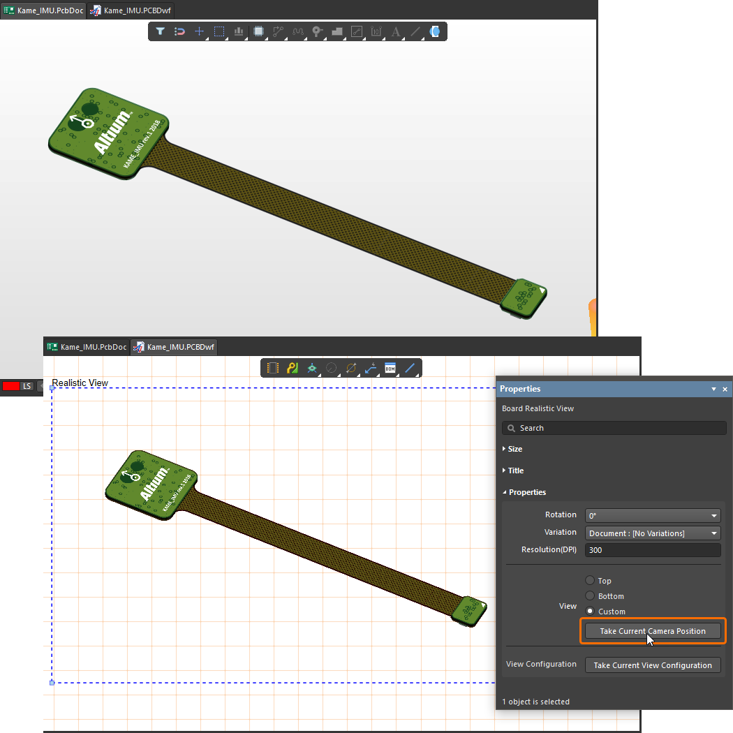 )を採用します。
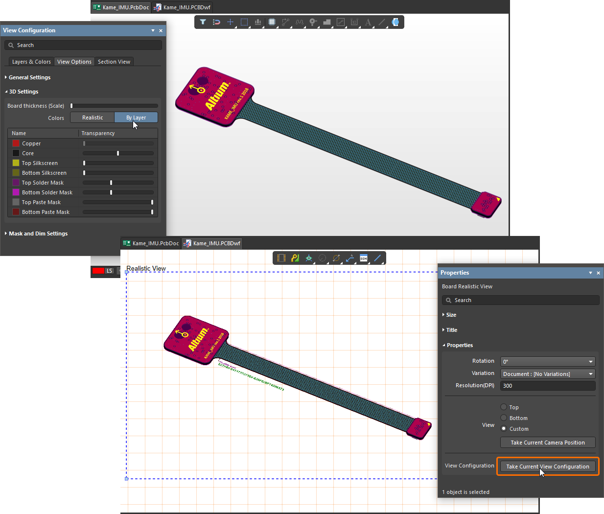 )で定義され、現在 PCB エディタの 3D ビューに適用されている表示設定を採用するようになります。

 )。
)。
を示す配置済みビアタイプビュー")
 )。
)。


 )に
)に 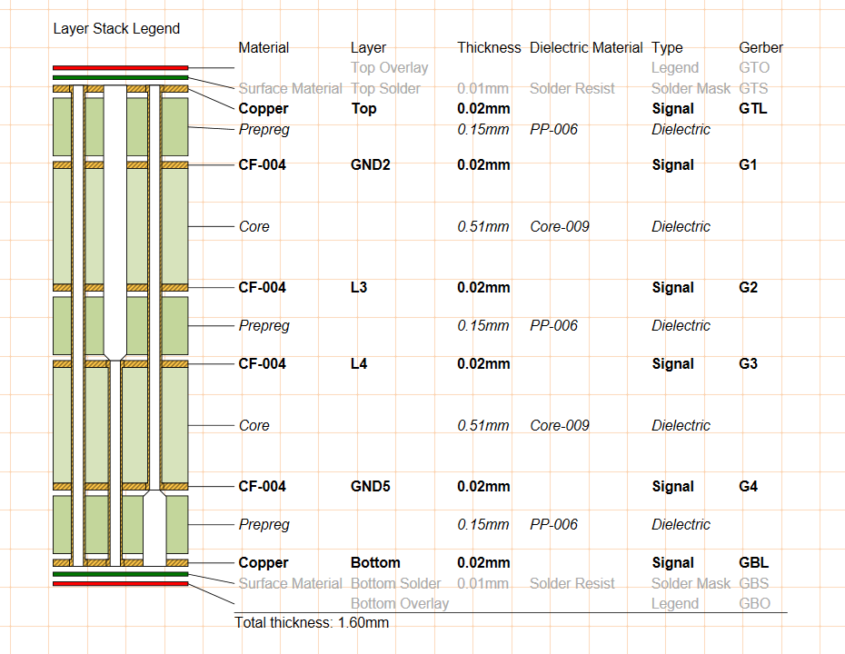 )。バックドリルの詳細は
 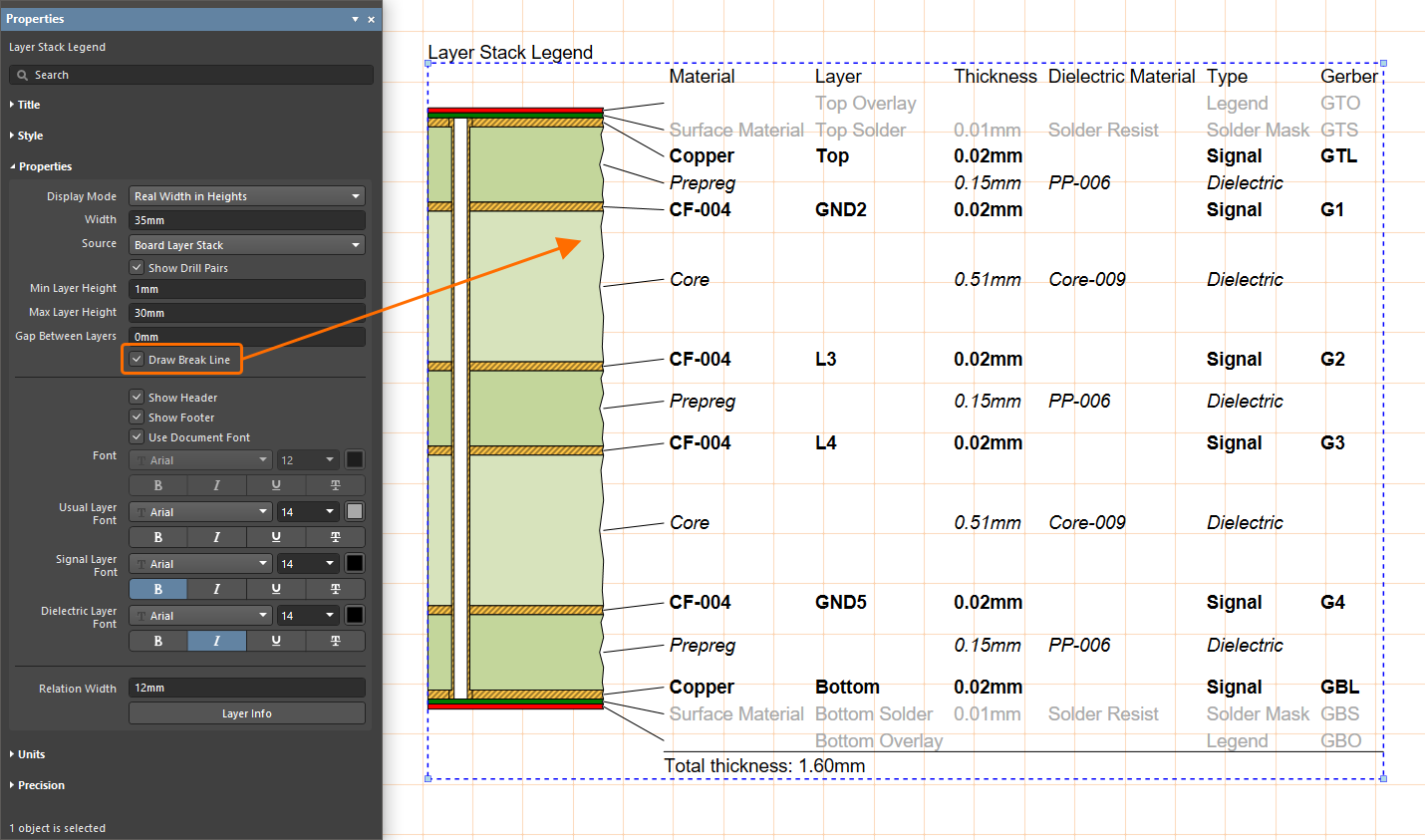 )として表示されます。
 )を選択できます。用意されているオプションは次のとおりです。
 )の
)の  AI で翻訳