デザイン・ディレクティブ(Design Directives)は、設計キャプチャ中に回路図へ配置するオブジェクトで、ソフトウェアの他の機能へ渡す指示を指定するための手段です。さまざまなデザイン・ディレクティブが用意されており、主に次の2つの用途で使用します。
-
ソース回路図ドキュメントの自動コンパイルに関連するディレクティブ。
-
回路図シート上で定義した情報をPCBへ渡すために使用するディレクティブ。
以降のセクションでは、これらの領域と関連するディレクティブについて詳しく説明します。
コンパイル関連ディレクティブ
設計は時間とともに進化し、段階的にキャプチャされます。各段階が固まるたびに、設計全体から切り離してその段階だけを単独で確認したいことは珍しくありません。キャプチャ工程の途中段階で個別の回路図ドキュメント(またはプロジェクト全体)をコンパイルすると、まだキャプチャされていない回路や、回路断片間のインターフェース配線が未完成であることに起因する多数のエラーメッセージが出ることがよくあります。こうしたメッセージは実質的な価値がなく、重要な情報の周りにノイズを増やすだけです。これらのコンパイルエラーを抑制する最も手早く簡単な方法は、No ERC または Compile Mask ディレクティブを配置することです。
No ERC ディレクティブ
No ERC ディレクティブは回路のノード上に配置し、回路図プロジェクトの検証時に検出される Electrical Rule Check の警告および/またはエラー違反条件 の報告をすべて抑制します。詳細は Validating Your Design Project ページを参照してください。
Compile Mask ディレクティブ
No ERC ディレクティブは、設計内の違反しているピン、ポート、シートエントリ、ネットの数が少ない場合の抑制に適しています。しかし場合によっては、コンポーネントを含む設計の一部セクション全体を除外したいことがあります。Compile Mask ディレクティブ(Place » Directives » Compile Mask コマンド)を使用するか、Active Bar のディレクティブ・ドロップダウンにある Compile Mask ボタン( )をクリックすると、含まれる設計領域をコンパイラから効果的に隠し、未完成でコンパイルエラーを生成すると分かっている回路に対するエラーチェックを手動で防止できます。これは、アクティブなドキュメントまたはプロジェクトをコンパイルして他の特定領域の設計整合性を確認したい一方で、未完成部分に関連するコンパイラ生成メッセージの「ノイズ」を避けたい場合に非常に有用です。
名前が示すとおり、このディレクティブは、定義したマスクの境界内に入るオブジェクトをコンパイラが無視するよう指示します。マスクは、ノートや矩形オブジェクトと同様に配置します。
次の画像の例では、LCD1 デバイスへの配線がまだ未完成です。この回路図(Project » Validate PCB Project)だけをコンパイルすると、未完成回路に起因する多数の違反メッセージ(下図)が表示されます。画像にカーソルを合わせると、未完成回路の周囲に Compile Mask ディレクティブを配置した場合の効果を確認できます。これらの違反はコンパイラにより無視され、完全に配線されている回路図上の残りの回路はチェックされます。なお、真にマスクされるオブジェクト(マスクの外接矩形内に完全に収まるもの)はグレー表示になります。

画像にカーソルを合わせると、未完成回路によるコンパイラ違反を隠すために Compile Mask ディレクティブを使用した効果が表示されます。
Compile Mask は、展開(フルフレーム)または折りたたみ(小さな三角形)のいずれかのモードで表示できます。これらのモードは、それぞれマスクが有効/無効である状態に対応します。配置済み Compile Mask の左上隅をクリックして表示モードを切り替えます。この機能は、設計フローの一部としてシミュレーションを含む場合に役立ちます:
learn more。
Compile Mask は回転や X/Y 軸方向のミラーが可能ですが、内部の設計回路の向きには影響しません。
Compile Mask
 上記回路図の左側に配置された Compile Mask。
概要
Compile Mask は、Project » Validate Project command を使用して検証を行う際に、含まれる設計領域をコンパイラから効果的に隠すためのデザイン・ディレクティブです。未完成で検証エラーを生成する回路に対して、エラーチェックを手動で防止する手段を提供します。Compile Mask は、プロジェクトを検証して他の特定領域の設計整合性を確認する必要がある一方で、未完成部分に関連するコンパイラ生成メッセージの煩雑さを避けたい状況で有用です。
「Compile Mask」という名称ですが、このディレクティブはコンパイル行為そのものには関連しません。コンパイルは Altium Designer の Dynamic Compilation 機能により、各ユーザー操作の後に自動的に実行されます。Compile Mask が効いてくるのは、ユーザーが手動でプロジェクトの検証を実行する場合で、これはコンパイルとは別個のプロセスであり、ユーザーが明示的に開始する必要があります。検証では、
Project Options ダイアログの
Error Reporting および
Connection Matrix タブで定義された設定と連動して、プロジェクト内の回路図ドキュメントに対する電気的/作図上のエラーをチェックします。
利用可能範囲
Compile Mask は、Schematic Editor のみで配置できます。Compile Mask を配置するには次のいずれかを行います。
-
メインメニューから Place » Directives » Compile Mask command をクリックします。
-
デザインスペース上部にある Active Bar のディレクティブ・ドロップダウンで Compile Mask ボタン(
 )をクリックします。関連コマンドにアクセスするには Active Bar ボタンをクリックして保持します。コマンドを一度使用すると、そのコマンドが Active Bar の該当セクションの最上位項目になります。
-
回路図エディタ内で右クリックし、Place » Directives » Compile Mask をクリックします。
配置
コマンドを起動すると、カーソルが十字カーソルに変わり、Compile Mask の配置モードになります。配置は次の手順で行います。
-
カーソルを位置決めし、クリックまたは Enter を押してマスクの最初の角を固定します。
-
カーソルを移動してマスクのサイズを調整し、コンパイラから隠したい設計領域を完全に囲むようにしたら、クリックまたは Enter を押して対角の角を固定し、マスクの配置を完了します。マスク境界内に完全に収まる設計オブジェクトはグレー表示になります。
-
さらに Compile Mask を配置し続けるか、右クリックまたは Esc を押して配置モードを終了します。
グラフィカル編集
この編集方法では、デザインスペース上で配置済み Compile Mask オブジェクトを直接選択し、サイズ、形状、位置をグラフィカルに変更できます。
Compile Mask は、アクティブ(フルフレーム)または折りたたみ(枠付き三角形)のいずれかのモードで表示できます。これらはそれぞれ、マスクが有効/無効である状態に対応します。配置済み Compile Mask の左上隅にある ▲ または ▼ アイコンをクリックして表示モードを切り替えます。
します。") 左上隅の三角形をクリックして Compile Mask を折りたたみ(無効化)します。
左上隅の三角形をクリックして Compile Mask を折りたたみ(無効化)します。
アクティブ(展開)状態の Compile Mask オブジェクトを選択すると、次の編集ハンドルが使用できます。
。") 選択された Compile Mask(アクティブ時)。
選択された Compile Mask(アクティブ時)。
-
A をクリックしてドラッグすると、縦横方向を同時にリサイズできます。
-
B をクリックしてドラッグすると、縦方向と横方向を個別にリサイズできます。
-
編集ハンドルから離れた Compile Mask 上の任意の場所をクリックしてドラッグすると、位置を移動できます。ドラッグ中に Compile Mask を回転(Spacebar/Shift+Spacebar)またはミラー(X 軸/Y 軸方向のミラーはそれぞれ X または Y キー)できます。
Compile Mask が折りたたみ状態の場合、ドラッグして新しい位置へ移動することで位置のみをグラフィカルに変更できます。
Locked プロパティが有効なオブジェクトをグラフィカルに変更しようとすると、編集を続行するか確認するダイアログが表示されます。Preferences ダイアログの Schematic – Graphical Editing ページで Protect Locked Objects オプションが有効で、かつその設計オブジェクトの Locked オプションも有効な場合、そのオブジェクトは選択もグラフィカル編集もできません。ロックされたオブジェクトをクリックして選択し、List panel で Locked プロパティを無効にするか、Protect Locked Objects オプションを無効にしてオブジェクトをグラフィカルに編集してください。
非グラフィカル編集
次の非グラフィカル編集方法が利用できます。
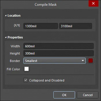
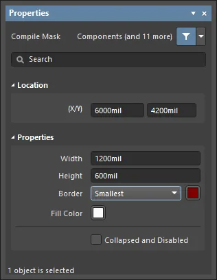
Compile Mask ダイアログまたは Properties パネルによる編集
Panel page: Compile Mask Propertiesこの編集方法では、関連する Compile Mask ダイアログおよび Properties パネルモードを使用して、Compile Mask オブジェクトのプロパティを変更します。
配置後、Compile Mask ダイアログは次の方法で開けます。
-
配置済み Compile Mask オブジェクトをダブルクリックします。
-
Compile Mask オブジェクトを選択し、右クリックしてコンテキストメニューから Properties を選択します。
配置中は、Properties パネルの Compile Mask モードを Tab キーで開けます。Compile Mask を配置すると、すべてのオプションが表示されます。
配置後は、Properties パネルの Compile Mask モードを次のいずれかの方法で開けます。
-
すでに Properties パネルがアクティブな場合は、Compile Mask オブジェクトを選択します。
-
Compile Mask オブジェクトを選択した後、デザインスペース右下の Panels ボタンから Properties panel を選択するか、メインメニューから View » Panels » Properties を選択します。
ダイアログとパネルで利用できるオプション自体は同じですが、オプションの並び順や配置がわずかに異なる場合があります。
複数オブジェクトの編集
Propertiesパネルは複数オブジェクト編集に対応しており、現在選択されているすべてのオブジェクトで共通(同一)となっているプロパティ設定を変更できます。同一タイプのオブジェクトを、手動で複数選択した場合、Find Similar Objects dialog()で選択した場合、またはFilter()やList()パネルを通じて選択した場合、Propertiesパネルのフィールドでアスタリスク(*)表示になっていない項目は、選択中のすべてのオブジェクトに対して編集できます。
リストパネルによる編集
Panel pages: List Panels、SCH Filter
A List パネルは、1つ以上のドキュメントに含まれる設計オブジェクト種別を表形式で表示し、オブジェクト属性の迅速な確認と変更を可能にします。適切なフィルタリング(パネルのIncludeオプションでオブジェクト種別を選択する、該当するFilter パネルまたはFind Similar Objects dialog()を使用する等)と組み合わせることで、アクティブなフィルタの範囲に該当するオブジェクトだけを表示できます。その後、一覧表示されたオブジェクトのプロパティはListパネル上で直接編集できます。
Compile Mask Properties
Schematic Editorのオブジェクトプロパティは、配置されたオブジェクトの見た目(ビジュアルスタイル)、内容、動作を指定するための設定オプションです。各オブジェクトタイプのプロパティ設定は、次のように定義されています。
ダイアログとパネルで利用できるオプション自体は同じですが、オプションの並び順や配置がわずかに異なる場合があります。
位置
-
(X/Y)
-
X (第1フィールド)- 現在の設計スペース原点に対する、オブジェクト参照点の現在のX(水平)座標です。編集してオブジェクトのX位置を変更します。値はメートル法/ヤード・ポンド法のいずれでも入力でき、現在のデフォルト単位と異なる単位で入力する場合は単位を付けてください。
-
Y (第2フィールド)- 現在の原点に対する、オブジェクト参照点の現在のY(垂直)座標です。編集してオブジェクトのY位置を変更します。値はメートル法/ヤード・ポンド法のいずれでも入力でき、現在のデフォルト単位と異なる単位で入力する場合は単位を付けてください。
プロパティ
-
Width - オブジェクトの幅を入力します。
-
Height - オブジェクトの高さを入力します。
-
Border - ドロップダウンから希望する枠線を選択します。
-
Fill Color - カラーボックスをクリックして、オブジェクトの希望する色を選択します。
-
Collapsed and Disabled - チェックすると、オブジェクトを折りたたんで無効化します。
PCB関連ディレクティブ
統合設計環境として、Altium Designerでは基板レイアウト前にPCB要件を定義できます。これは、回路図シート上に配置したオブジェクトにパラメータを追加し、指定することで実現します。
コンポーネント、シートシンボル、ポートなどの特定の回路図設計オブジェクトでは、該当するパラメータをそのオブジェクトのプロパティの一部として追加します。一方、ワイヤやバスなどのネットオブジェクトでは、ワイヤ/バスのプロパティとして直接パラメータを追加できません。代わりに、必要な情報を保持するためのパラメータは、専用の設計ディレクティブを使って指定します。
ディレクティブを使用して次の情報を指定でき、設計同期時に適切なPCB側の定義へ転送されます。
回路図内に設計ディレクティブを含めることで、設計エンジニアは明示的な設計制約を指定でき、回路図が設計のマスターレコードであり続けることが保証されます。設計の修正は回路図側のみで行い、PCBへ反映(プッシュ)します。これは、複数人が設計に関わる場合、特に地理的に離れて作業している場合に重要になります。メールのやり取りや電話連絡の連鎖で相互に伝達しようとするのではなく、設計をキャプチャしている担当者が、レイアウト段階で特定の制約が確実に適用されるようにできます。
この機能の中核となるのが、Parameter Set directive()です。
これは本質的にユーザー定義のParameter Setオブジェクトで、回路図設計内のネットオブジェクトに関連付けられます。ワイヤ、バス、またはシグナルハーネス上にPCB Layoutディレクティブを配置し、関連するネットに対して1つ以上の設計制約を定義します。回路図からPCBを作成する際、PCB layoutディレクティブ内の情報は、関連するPCB設計ルールの作成に使用されます。PCB Layoutディレクティブで指定した情報は、そのディレクティブが接続されているネット(またはネットの集合)にのみ適用されます。

Parameter Setディレクティブ。
これは、Parameter Setディレクティブが接続されているネットを対象とする任意数のパラメータを格納するコンテナとして機能します。パラメータを持たないデフォルトのParameter Setディレクティブを配置(Place » Directives » Parameter Set)し、必要なパラメータを後から追加することもできます。以降のセクションでは、これらのパラメータベースのディレクティブの使用方法を詳しく見ていきます。ユーザー定義(Parameter Set)と、事前定義(Differential Pair)のパラメータセットディレクティブの両方が利用可能です。空のパラメータセットと事前定義パラメータセットの違いは、事前定義パラメータセットには後述するパラメータが含まれている点だけです。
Moving from Directives to the Constraint Manager
設計要件を定義する従来の方法は、回路図エディタとPCBエディタで別々に扱うことでした。回路図エディタではディレクティブで定義し、PCBエディタではDesign Rules()で定義します。この分離は、設計要件を定義するための独立したエディタであるConstraint Manager()の導入により解消され、設計プロセスのどの段階でも設定・編集できるようになりました。1つのプロジェクトで使用できるアプローチはどちらか一方のみです。簡単な確認方法は、DesignメニューにConstraint Manager項目があるかを見ることです。もし無く(代わりにPCBエディタのDesignメニューにRules項目がある場合)、そのプロジェクトは旧来のDesign Rules方式を使用しています。
Constraint Managerが使用されている場合、Parameter SetおよびDifferential Pairディレクティブで定義されたネットクラス、差動ペア、差動ペアクラス、およびルールは、回路図からPCBを更新する際にnot検出され転送されます。転送されるのは、Constraint Managerで定義されたネットクラス、差動ペア、差動ペアクラス、およびルールのみです。
また、回路図に配置されたディレクティブから、ルール、ネットクラス、差動ペア、および差動ペアクラスを、回路図からアクセスしたConstraint ManagerのPhysicalまたはElectricalビューの右クリックメニューにあるImport from Directivesコマンドを使ってインポートできます(learn more)。ディレクティブからConstraint Managerへデータをインポートして変更を保存すると、インポートされたディレクティブは回路図設計スペース上で青色(やや異なるシンボル)で区別表示されます。これは、ディレクティブからConstraint Managerへの一方向の移行が行われたことを示し、青色のディレクティブは読み取り専用オブジェクト(以後編集不可)になります。
Parameter Set

Parameter Set
概要
パラメータセットは、回路図設計内のネットタイプのオブジェクトに設計仕様を関連付けるための設計ディレクティブです。たとえば、パラメータセットを使用して2つのネットが差動ペアのメンバーであることを宣言できます。ソフトウェアは、パラメータセット内に特定の名前のパラメータが存在することをもとに、配置している設計ディレクティブの種類を判定します。
利用可能範囲
パラメータセットは回路図エディタでのみ配置できます。デフォルト(空)と事前定義(Differential Pair)の両方のパラメータセットディレクティブが利用可能です。空のパラメータセットと事前定義パラメータセットの違いは、事前定義パラメータセットには下記のとおりパラメータが含まれている点だけです。
対応するコマンドは、メインのPlaceメニューから次のようにアクセスします。
| • |
Place » Directives » Parameter Set |
 |
| • |
Place » Directives » Differential Pair |
 |
配置
パラメータセットは、次の対象にパラメータを付与するために使用できます。
コマンドを起動すると、カーソルが十字に変わり、設計ディレクティブ配置モードに入ります。 配置は次の操作で行います。
-
カーソルをワイヤまたは他のネットオブジェクト上に合わせ、クリックするかEnterを押して配置します。
-
続けてディレクティブを配置するか、右クリックまたはEscを押して配置モードを終了します。
配置中(パラメータセットがカーソルに追従して浮いている間)に実行できる追加操作は次のとおりです。
-
Tabキーを押して配置を一時停止し、PropertiesパネルのParameter Set mode()にアクセスします。ここからプロパティをその場で変更できます。配置を再開するには、設計スペースの一時停止ボタンのオーバーレイ( )をクリックします。
-
移動の初期方向に応じて、移動方向を水平軸または垂直軸に制限するには、Alt キーを押します。
-
円弧を反時計回りに回転するには Spacebar、時計回りに回転するには Shift+Spacebar を押します。この操作はオブジェクトをドラッグ中にも実行できます。回転は 90° 刻みです。
-
配置モード中に X または Y キーを押すと、パラメータセットを X 軸または Y 軸に沿って反転できます。
配置中に属性を変更することは可能です(
Tab で
Properties パネルを表示)。ただし、
Schematic – Defaults page の
Permanent オプションが
Preferences ダイアログで有効になっていない限り、これらは以降の配置に対するデフォルト設定になります。このオプションが有効な場合、変更は配置中のオブジェクトと、同一の配置セッション中に続けて配置するオブジェクトにのみ影響します。
グラフィカル編集
この編集方法では、配置済みのパラメータセット・ディレクティブを設計領域で直接選択し、位置や向きをグラフィカルに変更できます。
設計領域でパラメータセット・ディレクティブを選択すると、ディレクティブの周囲に破線のボックスが表示されます。このボックスはディレクティブが占有する領域のみを囲みます。セット内の各メンバーパラメータのうち可視化が有効なものについては、パラメータのテキストフィールドとディレクティブ本体を結ぶ破線が表示され、関連付けを示します。
破線ボックス内の任意の場所をクリックしてドラッグし、必要に応じてパラメータセットを再配置します。ドラッグ中に、パラメータセットは回転(Spacebar/Shift+Spacebar)またはミラー(X 軸または Y 軸に沿ってミラーするには X または Y キー)できます。
パラメータセットの テキストフィールド(親ディレクティブとは独立してグラフィカル編集可能)は、Preferences ダイアログの Schematic – Defaults page にある Style オプションを変更することでサイズに関してのみ調整できます。そのため、これらのオブジェクトを選択しても編集ハンドルは利用できません。
破線ボックス内の任意の場所をクリックしてドラッグし、必要に応じてテキストオブジェクトを再配置します。ドラッグ中に、テキストオブジェクトは回転(Spacebar/Shift+Spacebar)またはミラー(X 軸または Y 軸に沿ってミラーするには X または Y キー)できます。
Preferences ダイアログの Schematic – General page で Enable In-Place Editing オプションが有効な場合、(ルールとして追加されたパラメータを除き)設計領域でパラメータ値を直接編集できます。テキストオブジェクトを選択し、さらに 1 回クリックして機能を呼び出します。必要に応じて新しい値を入力し、テキストオブジェクトの外側をクリックするか Enter を押して変更を反映します。
Locked プロパティが有効なオブジェクトをグラフィカルに変更しようとすると、編集を続行するか確認するダイアログが表示されます。Preferences ダイアログの Schematic – Graphical Editing ページで Protect Locked Objects オプションが有効で、さらにその設計オブジェクトの Locked オプションも有効な場合、そのオブジェクトは選択もグラフィカル編集もできません。ロックされたオブジェクトをクリックして選択し、List パネルで Locked プロパティを無効にするか、Protect Locked Objects オプションを無効にしてグラフィカル編集できるようにします。
非グラフィカル編集
以下の非グラフィカル編集方法が利用できます。
Parameter Set ダイアログまたは Properties パネルによる編集
Panel page: Parameter Set Properties
この編集方法では、関連する Parameter Set ダイアログと、Properties パネルモードを使用して、パラメータセット・オブジェクトのプロパティを変更します。

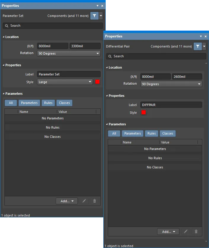
1 枚目の画像の Parameter Set dialog と、2 枚目の画像の Properties パネルの Parameter Set mode
配置後、Parameter Set ダイアログは次の方法で開けます。
-
配置済みのパラメータセット・オブジェクトをダブルクリックする。
-
パラメータセット・オブジェクト上にカーソルを置き、右クリックしてコンテキストメニューから Properties を選択する。
配置中は、Properties パネルの Parameter Set モードを Tab キーで開けます。パラメータセットを配置すると、すべてのオプションが表示されます。
配置後、Properties パネルの Parameter Set モードは次のいずれかの方法で開けます。
-
Properties パネルがすでにアクティブな場合は、パラメータセット・オブジェクトを選択する。
-
パラメータセット・オブジェクトを選択した後、設計領域右下の Panels ボタンから Properties パネルを選択するか、メインメニューから View » Panels » Properties を選択する。
Preferences dialog の
Schematic – Graphical Editing page で
Double Click Runs Interactive Properties オプションが無効(デフォルト)の場合、プリミティブをダブルクリックするか、選択したプリミティブを右クリックして
Properties を選ぶとダイアログが開きます。
Double Click Runs Interactive Properties オプションが有効な場合は、
Properties panel が開きます。
Parameter Set のプロパティは、配置モードに入る前に
Preferences ダイアログの
Schematic – Defaults page からアクセスできます。これにより、オブジェクトのデフォルトプロパティを変更でき、以降に配置するオブジェクトに適用されます。
複数オブジェクトの編集
Properties パネルは複数オブジェクト編集をサポートしており、現在選択されているすべてのオブジェクトで同一のプロパティ設定を変更できます。同一タイプのオブジェクトを手動で複数選択するか、Find Similar Objects dialog、または Filter/List パネルを通じて選択した場合、アスタリスク(*)表示になっていない Properties パネルのフィールド項目は、選択中のすべてのオブジェクトに対して編集できます。
List パネルによる編集
Panel pages: List Panels、SCH Filter
List パネルでは、1 つ以上のドキュメントに含まれる設計オブジェクトを表形式で表示でき、オブジェクト属性の迅速な確認と変更が可能です。適切なフィルタリング(該当する Filter panel、または Find Similar Objects dialog を使用)と組み合わせることで、アクティブなフィルタの範囲に該当するオブジェクトのみを表示でき、より高い精度と効率で複数の設計オブジェクトを対象に編集できます。
注記
Parameter Set Properties
回路図エディタのオブジェクトプロパティは、配置されたオブジェクトの表示スタイル、内容、動作を指定する定義可能なオプションです。
各オブジェクトタイプのプロパティ設定は、2 つの異なる方法で定義されます。
-
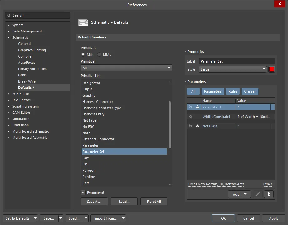
Pre-placement settings– ほとんどの Parameter Set オブジェクトのプロパティ(または論理的に事前定義できるもの)は、Preferences dialog(デザインスペース右上の  ボタンからアクセス)内の Schematic – Defaults page で編集可能なデフォルト設定として用意されています。Primitive List 内でオブジェクトを選択すると、右側にそのオプションが表示されます。
-
Post-placement settings – Parameter Set オブジェクトのすべてのプロパティは、デザインスペースで Parameter Set を選択しているときに、 Parameter Set dialogs および Properties panel で編集できます。
Double Click Runs Interactive Properties オプションが
Preferences dialog の
Schematic – Graphical Editing page で無効(デフォルト)の場合、プリミティブをダブルクリックするか、選択中のプリミティブを右クリックして
Properties を選ぶと、ダイアログが開きます。
Double Click Runs Interactive Properties オプションが有効の場合は、
Properties panel が開きます。
ダイアログとパネルでオプション自体は同じですが、並び順や配置が多少異なる場合があります。
以下のプロパティ一覧では、 Preferences dialog でデフォルト設定として利用できないオプションは「Properties panel only」と注記しています。
Location
-
(X/Y)
-
X (first field) – 現在のデザインスペース原点に対する、オブジェクト参照点の現在の X(水平)座標です。編集してオブジェクトの X 位置を変更します。値はメートル法/ヤード・ポンド法のどちらでも入力でき、現在のデフォルト単位と異なる単位で入力する場合は単位を付けてください。
-
Y (second field) – 現在の原点に対する、オブジェクト参照点の現在の Y(垂直)座標です。編集してオブジェクトの Y 位置を変更します。値はメートル法/ヤード・ポンド法のどちらでも入力でき、現在のデフォルト単位と異なる単位で入力する場合は単位を付けてください。
-
Rotation – ドロップダウンで回転を選択します。
Properties
-
Label – パラメータセットのラベルです。必要に応じて編集します。
-
Style – ドロップダウンでスタイルを選択します。カラーボックスをクリックするとドロップダウンが開き、デフォルト色を選択できます。
Parameters
-
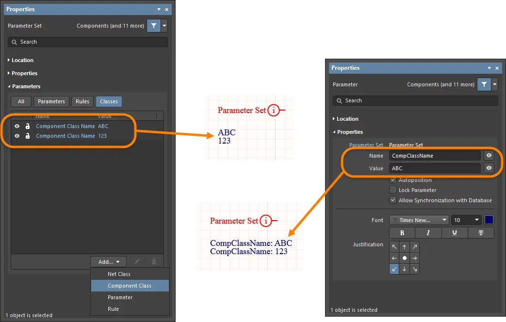
Grid – 現在選択されているパラメータに関連付けられたパラメータの Name と Value を一覧表示します。追加後は Name と Value フィールドを編集できます。Value はフィールドをクリックして任意のテキストを入力することで名前を付けられます。Name フィールドは、Parameter Set オブジェクトの Properties panel モードで Ctrl+Click を使用した場合にのみ変更できます。この方法では Properties panel の Parameter モードが開き、Name フィールドに希望の名前を入力できます。ロックアイコン(
 )で一覧内パラメータのロック/ロック解除を行います。目のアイコンでパラメータの表示/非表示を切り替えます。All と各パラメータボタンを切り替えることで、この領域に「すべて/個別/なし」を表示できます。各ボタンがグレーのときは無効、青のときは有効です。
-
Add – ドロップダウンを使用してクラスの種類を追加します:
-
Net Class – 新しいネットクラスを追加する場合に選択します。
-
Component Class – 新しいコンポーネントクラスを追加する場合に選択します。このオプションは、Parameter Set dialog または Properties panel の Parameter Set 反復でのみ利用できます。
ブランケット内のコンポーネントに対してパラメータを設定するために、新しいクラス Component Class Name を追加できます。Component Class Name をコンポーネント(またはコンポーネント群)に関連付けると、ネットクラスの場合と同様に、コンポーネントクラス、その名前、およびメンバーに関する情報が PCB に送信されます。
-
Diff. Pair Net Class – 新しい差動ペアのネットクラスを追加する場合に選択します。このオプションは、Parameter Set dialog または Properties panel の Differential Pair 反復でのみ利用できます。
-
Parameter – 新しいパラメータを追加する場合に選択します。
-
Rule – クリックすると
![]() Choose Design Rule Type dialog が開き、新しいルールを選択できます。新しいルールを選択して OK をクリックすると、Edit PCB Rule (From Schematic) dialog が開き、必要に応じて新しいルールを編集できます。
Choose Design Rule Type dialog が開き、新しいルールを選択できます。新しいルールを選択して OK をクリックすると、Edit PCB Rule (From Schematic) dialog が開き、必要に応じて新しいルールを編集できます。
ディレクティブから Constraint Manager へデータをインポートして同期し、
Constraint Manager で変更を保存した後は、対応するディレクティブの
Properties panel で、新規追加や既存のネットクラス/差動ペアクラス/コンポーネントクラス/ルールの編集・削除を行うコントロールがグレーアウトします。
Constraint Manager にインポートされたエントリは、ディレクティブのプロパティでは基本的に読み取り専用となり、
Properties panel の
Parameters 領域上部にある
Constraint Manager ボタンでフィルタして除外できます。
鉛筆( )アイコンをクリックすると Edit PCB Rule (From Schematic) dialog が開き、選択項目を編集できます。
 をクリックすると選択項目を削除します。
-
Font Settings – 表示されているフォントをクリックしてフォントスタイルを変更します。このオプションは、ネットクラス/差動ペアネットクラス/パラメータ/ルールのいずれかを追加した後にのみ利用できます。
-
Other – ネットクラス/差動ペアネットクラス/パラメータ/ルールが追加されている場合、クリックしてドロップダウンを開き、追加オプションを変更します:
-
Show Parameter Name – 有効にするとパラメータ名を表示します。
-
Allow Synchronization with Database – 有効にするとデータベースと同期します。
-
X/Y – X および Y 座標を入力します。
-
Rotation – ドロップダウンで回転を選択します。
-
Autoposition – チェックすると自動配置を有効にします。
Placing Parameter Set Directives
この種類のディレクティブは、メインメニューから Place » Directives » Parameter Set コマンドを選ぶか、デザインスペース内で右クリックしたときに配置できます。デフォルトの parameter set ディレクティブを配置する場合、既存のパラメータはありません。parameter set は、回路図設計内のネットタイプのオブジェクトに設計仕様を関連付けるための設計ディレクティブです。たとえば、parameter set を使用して 2 本のネットを差動ペアのメンバーとして宣言できます。ソフトウェアは、parameter set 内に特定の名前のパラメータが存在することによって、配置している設計ディレクティブを判別します。
ユーザー定義のパラメータディレクティブに加えて、ルールベースのパラメータディレクティブは Choose Design Rule Type dialog から定義します。これは、パラメータに関連付けられた Properties panel モードからアクセスできます。手順は次のとおりです:
-
Parameter Set を配置する前に Tab を押すか、すでに配置済みの Parameter Set ディレクティブをダブルクリックして、Parameter Set mode of the Properties panel を表示します。
-
次に、Properties panel の Parameter Set mode の Parameters セクションにある Add ボタンをクリックし、ドロップダウンから Rule を選択して Choose Design Rule Type dialog でルールを選びます。

Editing the value for a rule.
Choose Design Rule Type dialog を使用して、ディレクティブにルールパラメータとして追加したいルールを選択します。ルールタイプをダブルクリックすると、関連する Edit PCB Rule (From Schematic) dialog にアクセスでき、ルールの制約を定義できます。
Edit PCB Rule (From Schematic) dialog に表示される具体的なプロパティは、選択した設計ルールに依存し、PCB エディタでそのルールに定義されているプロパティと同一になります。
たとえば、下の画像は Max-Min Width Rule 用の Edit PCB Rule (From Schematic) dialog を示しており、次のことができます: 全レイヤーの Min/Preferred/Max 設定を構成する、各レイヤーの幅設定を手動で定義する、または Impedance Profile を使用するよう選択する。インピーダンスプロファイルを選択する際に、実際の基板構造がすでに PCB エディタで定義されている場合は、Load the PCB Layer Stack and calculate the track width values するためのボードファイルも選択できます。
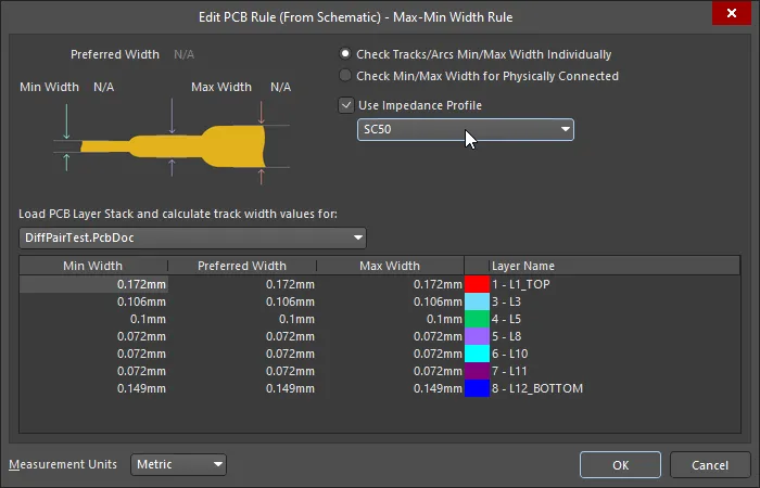 PCB が存在し、レイヤースタックが定義されている場合、計算された幅を回路図に読み込めます。
上に示したルールはネットのクラスに適用されました。これは、ネットをクラスにグループ化し、そのクラスに Max-Min Width Rule を適用するために、PCB Routing Directive を付加した Blanket Directive を配置することで実現しています(show image![]() )。
)。
各 PCB Design Rules と制約の詳細については、here をクリックしてください。
Measurement Units ドロップダウンフィールドを使用して、Metric または Imperial 単位を選択します。

選択したルールの制約を指定します。
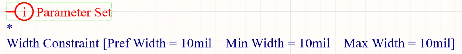
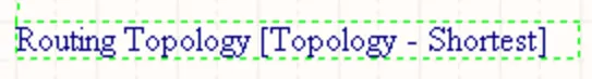
Parameters領域のエントリには、選択したルールタイプと指定した制約が表示されます。次の画像は、Parameter Setディレクティブに対して定義された幅制約ルールのパラメータを示しています。設計空間内にルールを表示するには、Rules領域内の可視性( )アイコンをクリックします。

Parameter Setディレクティブにより、特定のネットに対して複数のルール制約が定義されている例。
同期プロセスを通じて設計をPCBへ転送すると、ディレクティブに含まれる情報に基づいて、関連するデザインルールが作成されます。生成される各ルール名には、ルールの生成元を区別するために Schematic という語が使用されます。

PCB側で生成されたデザインルール。
同じParameter Setディレクティブに複数のパラメータを追加できるため、回路図をよりすっきりとまとめられることを覚えておいてください。
Net Classディレクティブの配置
Net Classディレクティブを使用すると、回路図上でユーザー定義のネットクラスを作成できます。Net Classディレクティブは、メインメニューから Place » Directives » Parameter Set コマンドを選択し、コマンドページのTip #2に記載されているとおり、パラメータセットをネットクラスディレクティブとして定義することで配置できます。回路図からPCBを作成する際、Net Classディレクティブ内の情報はPCB上の対応するNet Classを作成するために使用されます。ネットをネットクラスのメンバーにするには、該当するワイヤ、バス、またはシグナルハーネスにNet Classディレクティブをアタッチし、ディレクティブの ClassName パラメータを目的のクラス名に設定します。この機能を使用するには、Project OptionsダイアログのClass Generationタブの にある Generate Net Classes オプション(User-Defined Classes用)を有効にする必要があります。
ネットに対してNet Classディレクティブが定義されている場合、そのパラメータセットオブジェクトによって作成されるPCBデザインルールは、設計をPCBエディタへ転送した際にルールスコープがNet Classになります。Net Classディレクティブは、配置済みのParameter Setディレクティブにクラスを追加し、その値を必要なPCB Net Classに設定することで作成できます。
Net ClassはPCBエディタ内から作成することもできますが、ネットの論理的な機能やグルーピングは通常回路図の方がはるかに明確です。そのため、回路図側からプロセスを駆動する方が理にかなっています。
同期プロセスを通じて設計をPCBへ転送すると、ディレクティブに含まれる情報に基づいて、関連するネットクラスが作成されます。
Net Classディレクティブを
Blanket object にアタッチすると、そのBlanketでカバーされる個々のネットをメンバーとするネットクラスを作成できます。さらにPCB LayoutディレクティブもそのBlanketにアタッチされている場合、PCB Layoutディレクティブのルールパラメータは各個別ネットではなく、そのネットクラスを対象にします。変更をPCBドキュメントへインポートすると、(パラメータごとに)単一のデザインルールが作成され、スコープはネットクラスを対象とするように設定されます。
Blanketディレクティブの配置
Parameter Setディレクティブは、アタッチされた特定のネットのみを対象にできますが、Blanketディレクティブと組み合わせることで、スコープをBlanket内のすべてのネットに拡張できます。
このタイプのディレクティブは、メインメニューから Place » Directives » Blanket コマンドを選択して配置します。Blanketを配置する際は、単純な長方形形状または多角形形状を定義できます。後者は、シート上で必要なネットオブジェクトのカバー範囲をより精密に制御できます。
Blanketは対象となるネットを識別します。これらのネットに設計要件を適用するには、Blanketのエッジ上の任意の場所に Parameter Set ディレクティブを配置します。Blanketディレクティブの下にあるネットへ周辺(perimeter)ディレクティブを適用するには、そのネットに関連付けられたオブジェクト(ピン、ポート、ネットラベル、電源ポート、ワイヤ/バス/ハーネスのセグメント(両端を含む))がBlanketの境界内に入っている必要があります。ネットラベルなどのネット識別子については、ホットスポットがBlanket内にある必要がある点に注意してください。メンバーネットが期待どおりPCB Parameter Setへ渡らない場合は、Blanketの領域を適宜調整してみてください。
Blanketディレクティブがどのネットに適用されるかを確認するには、
Net Colors 機能を使用してハイライトします。
View » Set Net Colors メニューから必要な色を選択し、目的のBlanketディレクティブの外周をクリックします。特定のネットのハイライトを解除するには、
View » Set Net Colors » Clear Net Color コマンドを使用し、色を解除したいネットをクリックします。すべての回路図シートからネットの色付けを解除するには、
View » Set Net Colors » Clear All Net Colors コマンドを使用します。

Blanketディレクティブを使用して、Blanket内のネットにParameter Setディレクティブを適用する例。
Blanketディレクティブの使用例には、次のようなものがあります。
-
Parameter SetディレクティブをBlanketオブジェクトにアタッチし、そのルールパラメータをBlanketでカバーされる各個別ネットに適用する。
-
Parameter SetディレクティブをBlanketオブジェクトにアタッチし、Blanketでカバーされる個々のネットをメンバーとするParameter Setを作成する。
-
Differential PairディレクティブをBlanketオブジェクトにアタッチし、そのBlanketの範囲内にある差動ネットに基づいて差動ペアオブジェクトを作成する。
Parameter Setディレクティブを
Blanket object にアタッチすると、そのBlanketでカバーされる各個別ネットにルールパラメータを適用できます。さらにParameter SetディレクティブもそのBlanketにアタッチされており、かつParameter SetにNet Classパラメータが含まれている場合、Parameter Setディレクティブのルールパラメータは各個別ネットではなく、そのネットクラスを対象にします。変更をPCBドキュメントへインポートすると、(パラメータごとに)単一のデザインルールが作成され、スコープはネットクラスを対象とするように設定されます。
周辺(perimeter)のParameter Setディレクティブをコピーして別のBlanketディレクティブ、あるいは個別のワイヤ、バス、ハーネスにアタッチすることもできます。その結果、同じParameter Setディレクティブに関連付けられた追加のネットがすべて、同じ生成済みPCB Net Classに追加されます。
Blanketは、Parameter Setディレクティブと組み合わせることで、Blanketで定義された領域内に完全に含まれるコンポーネントに対して、コンポーネントクラスやコンポーネントパラメータを適用する用途にも使用できます。これを行うには、BlanketにアタッチされたParameter Setディレクティブのプロパティにある Add ボタンのドロップダウンから Component Class および Parameter オプションを使用します。コンポーネントクラスとパラメータに関する情報は、PCBを更新する際のECOプロセス中にプロジェクトPCBドキュメントへ転送されます。
Blanket
")
長方形のBlanketと多角形のBlanket(いずれもBlanketディレクティブがアタッチされている)
概要
Blanketは、ネットおよび/またはコンポーネントの集合の上に配置する、長方形または多角形形状のグループディレクティブオブジェクトです。Blanketに適用されたディレクティブ(Parameter Set オブジェクト)は、Blanketがカバーするすべてのネットとコンポーネントに適用されます。Blanketを配置する際は、単純な長方形形状または多角形形状を定義できます。後者は、シート上で必要なネットオブジェクトのカバー範囲をより精密に制御できます。
Blanketは、次の条件を満たすすべてのネットに適用されます。
-
Blanketで定義された領域内に完全に含まれている、または
-
Blanketの下にあるワイヤ/バス/ハーネスの、接続された端点(頂点)が少なくとも1つある、または
-
ワイヤ/バス/ハーネスにネットラベルがアタッチされており、そのネットラベルがBlanketの下にある。
コンポーネントについては、BlanketはBlanketで定義された領域内のすべてのコンポーネントに適用されます。
Blanketの外周に適用されるディレクティブ(Place » Directive)— たとえばNo ERC、Differential Pair、または特定のルール/クラスParameter Set — は、Blanketオブジェクトによって登録されたすべてのネットとコンポーネントに適用されます。Blanketは 無効化および非表示 にできます。
利用可能範囲
Blanketは回路図エディタでのみ配置できます。Blanketを配置するには:
-
メインメニューから Place » Directives » Blanket をクリックします。
-
設計空間の上部にある Active Bar のディレクティブドロップダウン内で、Blanketボタン(
 )をクリックします。Active Bar ボタンをクリックして保持すると、他の関連コマンドにアクセスできます。いったんコマンドを使用すると、そのコマンドは Active Bar の該当セクションの最上位項目になります。
-
回路図エディタ内で右クリックし、Place » Directives » Blanket をクリックします。
配置
長方形のBlanketを配置するには:
-
上記の手順に従ってコマンドを起動します。
-
カーソルを合わせてクリックするか、 Enter を押して、左上コーナーを配置します。
-
カーソルを合わせてクリックするか、 Enter を押して、右下コーナーを配置します。
-
右クリックするか、 Enter を押して配置を完了します。
-
続けてBlanketを配置するか、右クリックするか、 Esc を押して配置モードを終了します。
多角形形状のBlanketを配置するには:
-
配置コマンドを起動します。
-
カーソルを合わせてクリックするか、 Enter を押して、Blanketの開始点を固定します。
-
カーソルを合わせてクリックするか、 Enter を押して、Blanketの形状を定義する一連のセグメントを固定します。
-
最後のセグメントを配置したら、右クリックするか、 Esc を押して配置を完了します。ポリゴンを「閉じる」必要はありません。ソフトウェアが開始点と最後に配置したセグメントを接続するために必要なセグメントを追加し、自動的に形状を完成させます。
-
続けてBlanketを配置するか、右クリックするか、 Esc を押して配置モードを終了します。
Blanketのセグメント配置中に実行できる追加操作は次のとおりです:
-
Tabキーを押すと配置を一時停止し、PropertiesパネルのBlanketモードにアクセスできます。ここから線のプロパティをその場で変更できます。配置を再開するには、デザインスペースの一時停止ボタンのオーバーレイ(
 )をクリックします。
-
Spacebar を押して、未確定セグメントのコーナー方向を変更します。
-
Backspace を押して、Blanketの多角形形状を定義している際に、直前に確定したセグメントを削除します。 Backspace を続けて使用すると、順に前のセグメントが削除されます。
配置モードは、より細い点線で表示されます。これは多角形形状のBlanketを定義する際に特に有用です。追加のセグメントを確定する前に、Blanket全体の形状がどのようになるかを確認できます。複雑な形状/自己交差する多角形形状はサポートされていません。ソフトウェアがそのような形状の生成を防止します。
グラフィカル編集
この編集方法では、デザインスペース上で配置済みのBlanketオブジェクトを直接選択し、サイズ、形状、または位置をグラフィカルに変更できます。Blanketオブジェクトを選択すると、次の編集ハンドルが使用できます:
。") 選択された長方形および多角形のBlanket(グラフィカル編集ハンドル表示)。
選択された長方形および多角形のBlanket(グラフィカル編集ハンドル表示)。
セグメント中央の編集ハンドルをクリックしてドラッグすると、その辺を移動できます。
長方形のBlanketでは、コーナーの編集ハンドルをクリックしてドラッグすると、縦横方向を同時にリサイズできます。
編集ハンドルから離れたBlanketの外形線上をクリックしてドラッグすると、再配置できます。ドラッグ中にBlanketを回転または反転できます:
-
Spacebar を押すと、カーソル位置を中心にBlanketを反時計回りに回転します。Shift+Spacebarはカーソルを中心に時計回りに回転します。回転は90°刻みです。
-
X または Y キーを押すと、カーソル位置を基準にX軸またはY軸方向にBlanketを反転します。
多角形Blanketの形状変更は、複雑な形状/自己交差する形状になる場合は防止されます。
Locked プロパティが有効なオブジェクトをグラフィカルに変更しようとすると、編集を続行するか確認するダイアログが表示されます。
Preferences ダイアログの
Schematic – Graphical Editing ページで
Protect Locked Objects オプションが有効で、さらにそのデザインオブジェクトの
Locked オプションも有効な場合、そのオブジェクトは選択もグラフィカル編集もできません。ロックされたオブジェクトをクリックして選択し、
List パネルで
Locked プロパティを無効にするか、
Protect Locked Objects オプションを無効にして、オブジェクトをグラフィカルに編集してください。
非グラフィカル編集
次の非グラフィカル編集方法が利用できます。
BlanketダイアログまたはPropertiesパネルによる編集
Panel page: Blanketのプロパティ
この編集方法では、関連するBlanket ダイアログモードおよびPropertiesパネルモードを使用して、blanketオブジェクトのプロパティを変更します。
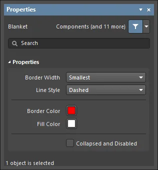 左がBlanket ダイアログ、右がPropertiesパネルのBlanketモード
配置後、Blanket ダイアログは次の方法で開けます:
-
配置済みblanketオブジェクトをダブルクリックする。
-
blanketオブジェクト上にカーソルを置き、右クリックしてコンテキストメニューからPropertiesを選択する。
配置中は、Tabキーを押すことでPropertiesパネルのBlanket モードにアクセスできます。blanketを配置すると、すべてのオプションが表示されます。
配置後、PropertiesパネルのBlanket モードは次のいずれかの方法で開けます:
-
Propertiesパネルがすでにアクティブな場合は、blanketオブジェクトを選択する。
-
blanketオブジェクトを選択した後、デザインスペース右下のPanels ボタンからProperties パネルを選択するか、メインメニューからView » Panels » Propertiesを選択する。
Preferences ダイアログの
Schematic – Graphical Editing pageで
Double Click Runs Interactive Properties オプションが有効(デフォルト)な場合、プリミティブをダブルクリックするか、選択したプリミティブを右クリックして
Propertiesを選ぶと、
Properties パネルが開きます。
Double Click Runs Interactive Properties オプションが無効の場合は、ダイアログが開きます。
ダイアログとパネルでオプションは同じですが、並び順や配置が多少異なる場合があります。
複数オブジェクトの編集
Propertiesパネルは複数オブジェクト編集に対応しており、現在選択されているすべてのオブジェクトで共通のプロパティ設定を変更できます。同一タイプのオブジェクトを手動で複数選択した場合、Find Similar Objects dialogを使用した場合、またはFilter/Listパネルを通じて選択した場合、アスタリスク(*)表示になっていないProperties パネルのフィールドは、選択中のすべてのオブジェクトに対して編集できます。
Listパネルによる編集
Panel pages: List Panels、SCH Filter
List パネルは、1つ以上のドキュメントに含まれる設計オブジェクト種別を表形式で表示し、オブジェクト属性の迅速な確認と変更を可能にします。適切なフィルタリング(パネルのIncludeオプションでオブジェクト種別を選択、または該当するFilter パネル/Find Similar Objects dialogを使用)と組み合わせることで、アクティブなフィルタの範囲に該当するオブジェクトのみを表示できます。その後、一覧表示されたオブジェクトのプロパティをList パネル上で直接編集できます。
フィルタリングのサポート
論理クエリ式でBlanketオブジェクトを対象にする際に、特に有用なキーワードが2つ用意されています。これらは、Blanketのプロパティに基づいて対象を絞り込む他のキーワード群を補完します。
-
Collapsed – オブジェクトが折りたたまれている(Compile Masksを対象にする場合にも有用)。このキーワードは、Query Helper使用時にSCH Functions - Fieldsカテゴリで見つかります。
-
IsBlanket – オブジェクトがBlanketであるかをテストします。このキーワードは、Query Helper使用時にSCH Functions - Object Type Checksカテゴリで見つかります。
必要に応じて、設計内のBlanketを対象として返すためのクエリ用論理式を作成します。Blanketを対象にした論理クエリ式の例:
IsBlanket And Collapsed – 現在折りたたまれているすべてのBlanketオブジェクトを対象にします。
IsBlanket And Not Collapsed – 現在折りたたまれていないすべてのBlanketオブジェクトを対象にします。
Blanketの無効化
配置後、左上の小さな三角形( )をクリックすると、Blanketを一時的に無効化できます。1回クリックで無効化して非表示にし、もう一度クリックすると再有効化します。これにより、設計から完全に削除しなくてもBlanketの影響を制御できる便利な方法になります。
Blanketは、
Propertiesパネルで
Collapsed and Disabled オプションを有効にするか、
SCH List パネルで編集する際に
Collapsed オプションを有効にしても無効化できます。
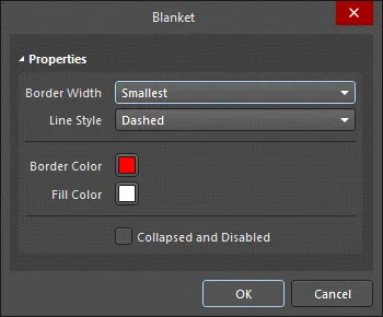
Blanket Properties
Schematic Editorのオブジェクトプロパティは、配置されたオブジェクトの表示スタイル、内容、動作を指定する定義可能なオプションです。各オブジェクト種別のプロパティ設定は、次の2つの方法で定義されます:
-
Pre-placement settings – ほとんどの Blanket オブジェクトプロパティ、または論理的に事前定義できるものは、Preferences ダイアログのSchematic - Defaults ページで編集可能なデフォルト設定として用意されています(デザインスペース右上の ボタンからアクセス)。Primitive List でオブジェクトを選択すると、右側にそのオプションが表示されます。
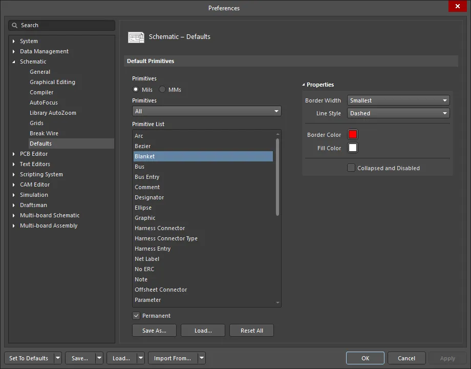
-
Post-placement settings – すべてのBlanket オブジェクトプロパティは、配置済みのBlanketをデザインスペースで選択すると、Blanket dialogおよびProperties panelで編集できます。
Schematic - Graphical Editing page(
Preferences dialog内)の
Double Click Runs Interactive Propertiesオプションが無効(デフォルト)の場合、プリミティブをダブルクリックするか、選択したプリミティブを右クリックして
Propertiesを選ぶと、dialogが開きます。
Double Click Runs Interactive Propertiesオプションが有効の場合は、
Properties panelが開きます。
dialogとpanelでオプション自体は同じですが、オプションの並び順や配置がわずかに異なる場合があります。
以下のオプション一覧では、Preferences dialogのデフォルト設定として利用できないオプションは「Properties panel only」として注記しています。
Properties
-
Border Width - ドロップダウンから希望するボーダー幅を選択します。
-
Line Style - ドロップダウンから希望する線種を選択します。
-
Border Color - カラーボックスをクリックして、ボーダーの色を選択します。
-
Fill Color - カラーボックスをクリックして、塗りつぶし色を選択します。
-
Collapsed and Disabled - チェックすると、Blanketを折りたたんで無効化します。
Indirect (Parameter-based) Directives
Parameter Set directivesは、パラメータを保持できない回路図上の設計オブジェクトをターゲットにする場合に必要ですが、パラメータを保持できるオブジェクトであれば、該当する回路図オブジェクトにパラメータとして追加(および定義)することで、設計ディレクティブを間接的に適用できます。要するに、これらはparameter-based directivesです。
パラメータベースのディレクティブの使用例としては、特定コンポーネントの高さ制限や、設計内のすべてのオブジェクトを対象とするクリアランス制約の追加などが挙げられます。制約を定義するために必要なパラメータは、ルールとしてオブジェクトに追加されます。
PCBと同期すると、回路図上のオブジェクトに追加されたパラメータベースのディレクティブはPCB設計ルールになります。対応するPCB設計ルールのスコープは、最初にそのパラメータが割り当てられたオブジェクトの性質によって決まります。次の表は、サポートされている「回路図パラメータ → PCBルールスコープ」オプションをまとめたものです。
いずれの場合も、ルールベースのパラメータを追加する方法は同じです。該当するタブまたはdialogから、次を実行します。
-
ルールとしてパラメータを追加します。
-
使用するルールタイプを選択します。
-
選択したルールタイプの制約を設定します。
回路図上のオブジェクトに設計ルールパラメータを追加すると、各ルールパラメータに一意のIDが付与されます。同じIDが、PCB上に作成される対応する設計ルールにも付与されます。この一意IDにより、ルールの制約は回路図側またはPCB側のどちらからでも編集でき、同期時に変更を反映できます。
コンポーネントクラスの指定
同様に、ターゲットとなるコンポーネントにClassNameパラメータを追加し、その値を希望するクラス名に設定することで、回路図上でコンポーネントクラスを定義できます。設計をPCBへ転送すると、定義したコンポーネントクラスが作成されます。
回路図で定義したComponent ClassesがPCBへ伝播するようにするには、Project Options dialogで次のオプションを設定する必要があります。
-
dialogのClass Generation tabにあるUser-Defined Classes region内のGenerate Component Classesオプションを有効にします。
-
dialogのComparator tabで、Differences Associated with Components » Extra Component Classes Mode設定を
Find Differencesにします。
上記のClass Generation tabオプションは、以下の画像に表示されています。画像にカーソルを合わせると、Comparator tabオプション設定を確認できます。

Component ClassesをPCBへ伝播するには、Class Generation tabのGenerate Component Classesオプションを有効にします。画像にカーソルを合わせると、Extra Component Classes Mode設定をFind Differencesにする必要があるComparator tabが表示されます。
定義後、クラスは各コンポーネントプロパティのProperties panel内Properties regionでロックできます。
PCBエディタでは、1つのコンポーネントが複数のComponent Classesに属することができます。これを回路図で定義するには、回路図コンポーネントのパラメータ値で、各PCB Component Class名をカンマで区切ります(show image![]() )。
)。
ディレクティブの印刷制御
デフォルトでは、すべての設計ディレクティブが回路図シートの印刷に含まれます。ただし、次の方法で変更できます。

必要に応じてディレクティブの印刷を制御してください。No ERCディレクティブについては、特定のシンボルスタイルは印刷し、他は除外するといった選択が可能です。


 AI で翻訳