Параметры — это текстовые строки общего назначения, которые являются дочерними объектами родительского объекта. Они идентифицируют родительский объект и добавляют к нему дополнительную информацию; доступ к ним осуществляется напрямую в панели Properties при выборе на листе схемы.
Например, компоненты на схеме активно используют параметры. Параметры компонента общего назначения могут применяться для самых разных задач, включая сведения о компоненте (например, мощность, напряжение и т. п.), сведения о поставщике (включая имя поставщика и номер детали), сведения о библиотечном компоненте (например, номер ревизии символа) и сведения для документации (например, URL со ссылкой на даташит компонента).
Параметры также можно задавать на уровне листа схемы (документа) и на уровне проекта. Параметры уровня документа используются для определения таких полей, как заголовок и номер документа, а параметры уровня проекта идеально подходят для определения таких полей, как разработчик или имя проекта.
 Параметры используются для объектов, документов и проектов, чтобы добавлять в проект детальную информацию. На изображении выше показан компонент.
Параметры добавляются или автоматически включаются как свойства родительского объекта и не размещаются независимо, как текстовая строка. Доступные типы параметров в целом можно разделить на системные и пользовательские; последние добавляются вручную.
Идентификатор и системные параметры
Объекты, размещаемые на схеме, автоматически получают набор ключевых системных параметров. Они предоставляют базовую информацию об объекте, которую система использует, чтобы различать имя, тип и источник данных родительского объекта. Встроенные системные параметры объектов включают, помимо прочего, свойства Comment, Description и Design Item ID (Library Reference). Системные параметры объекта доступны в разделе General панели Properties (на вкладке General), когда выбран родительский объект ( ). Если отдельный параметр видим и выбран в рабочей области, доступ к нему осуществляется через соответствующий режим панели Properties, как описано ниже(
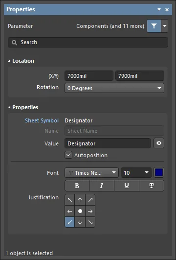 ).
).
Некоторые системные параметры нельзя сделать видимыми (и выбираемыми) на листе схемы, поэтому они недоступны в панели Properties. Для объектов-компонентов это Description, Design Item ID, Footprint, ссылки на модели, и т. д. Другие системные параметры, к которым нельзя получить прямой доступ на схеме, включают параметры документа (листа) и проекта.
Пользовательские параметры
Параметры можно добавлять к любым из следующих объектов проекта.
| Component |
Добавляйте пользовательские параметры в области Parameters панели Properties, когда выбран объект компонента (part), либо при определении компонента в редакторе Schematic Library. Системные параметры, такие как designator и comment, для объекта компонента присутствуют всегда, как описано выше. Доступ к панели Properties осуществляется двойным щелчком по объекту или щелчком правой кнопкой по объекту с выбором Properties в контекстном меню. Если панель Properties уже активна, выберите объект в рабочей области. |
| Part |
В области Parameters панели Properties , когда выбран объект Part. |
| Pin |
На вкладке Parameters панели Properties , когда выбран объект Pin внутри файла *.SchLib. |
| Port |
На вкладке Parameters панели Properties, когда выбран объект Port. |
| Sheet Symbol |
На вкладке Parameters панели Properties, когда выбран объект Sheet Symbol. |
| Document |
На вкладке Parameters панели Properties, когда включен режим Document Options (снимите выделение со всех объектов схемы или щелкните по свободному месту на листе документа). Ряд параметров по умолчанию автоматически включается в новый лист схемы в соответствии с примененным/шаблоном листа по умолчанию. |
| Project |
В диалоговом окне Project Options dialog (Project » Project Options). Параметры уровня проекта перечисляются и добавляются на вкладке Parameters этого диалога. |
Пользовательские параметры доступны в области Parameters панели Properties или в модальном диалоговом окне, когда выбран родительский объект. Параметры можно как добавлять, так и редактировать. Исключения — параметры проекта (через Project Options dialog) и параметры выводов компонента (через Pin Properties или модальный вид диалога Pin dialog). Если отдельный параметр видим и выбран в рабочей области, доступ к нему осуществляется через соответствующий режим панели Properties или модального диалога, как описано ниже.
. Второе: отдельный системный параметр в панели Properties.")
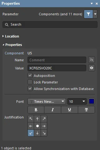 Первое: пользовательские параметры компонента в панели Properties (область Parameters). Второе: отдельный системный параметр в панели Properties.
Параметры, добавленные к родительскому объекту во время его размещения (см. выше), станут параметрами по умолчанию для последующих размещений этого родительского объекта, если для этого объекта не включена опция
Permanent на странице
Schematic – Default Primitives диалога
Preferences.
Когда эта опция включена, параметры, добавленные к размещаемому объекту, будут также добавляться к последующим объектам, размещаемым в рамках той же сессии размещения, но не будут переноситься на следующие сессии размещения для этого объекта.
Графическое редактирование
Видимые строки параметров можно редактировать графически прямо в рабочей области.
Щелкните и перетащите параметр, чтобы изменить его положение. Чтобы отредактировать строку параметра на месте:
-
Обведите курсором мыши объект параметра, удерживая нажатой кнопку мыши.
-
После выбора объект будет подсвечен зеленой рамкой.
-
Выберите Enter , чтобы начать редактирование текста.
-
После завершения редактирования снова нажмите Enter или щелкните вне строки, чтобы выйти из режима редактирования на месте.
 Строку параметра можно выбрать и редактировать непосредственно в рабочей области. Выделите всю строку, чтобы ввести текст поверх нее.
Параметры, которые видимы и выбираемы в рабочей области, можно перетаскивать на новое место и при этом поворачивать. Щелкните и перетащите строку параметра, используйте клавиши Spacebar и Shift+Spacebar для поворота с шагом 90°, затем щелкните, чтобы подтвердить новое положение/ориентацию.
См. Parameter String Positioning ниже для информации о параметре компонента Autopositioning и связанных опциях панели Properties.
Заблокированные параметры
Параметр, являющийся дочерним для Component Part, можно заблокировать — в этом случае его строки Name и Value нельзя редактировать. Это можно сделать так:
-
переключить значок замка ( ), связанный с его записью в области Parameters панели Properties или модального диалога для его родительского объекта, либо
-
установить флажок Lock Parameter в панели Properties, когда параметр выбран непосредственно в рабочей области.
После блокировки строку параметра нельзя редактировать в панели Properties, модальном диалоге (в разделе Parameters для родительского объекта) или в рабочей области с использованием редактирования на месте.
Параметры компонентов
Параметры компонентов — самые очевидные и наиболее часто используемые параметры схемы — включают дополнительные наборы специализированных параметров и функций, расширяющих возможности определения объектов компонентов.
Определение параметров в Schematic Library
Дочерние параметры родительского объекта компонента можно определить в исходнике библиотеки компонентов до егоo размещения на схеме. Панель Properties используется для редактирования и добавления параметров к записи компонента в редакторе Schematic Library так же, как и при работе с параметрами в редакторе Schematic .
При открытом документе библиотеки компонентов схемы выберите запись компонента в панели SCH Library, чтобы получить доступ к его свойствам параметров в панели Properties.
 Откройте свойства библиотечного компонента, выбрав его запись в панели SCH Library.
Designator и Comment библиотечного компонента по умолчанию не отображаются в рабочей области редактора Schematic Library, но их можно включить, установив опцию Show Comment/Designator в режиме Library Options панели Properties (Tools » Document Options) — доступно, когда в рабочей области не выбрано ни одного объекта.
Параметры, принадлежащие библиотечному компоненту, определяются и редактируются тем же процессом, что и для размещенных на схеме компонентов. Клавишу Tab можно использовать для создания или редактирования параметров «на лету» во время размещения объекта в рабочей области. Доступ к параметрам осуществляется через панель Properties или модальный диалог: основные системные параметры доступны на вкладке General панели, а пользовательские параметры добавляются/редактируются в раскрывающемся списке Parameters панели.
Чтобы добавить параметр, например, к выводу компонента, выберите объект
Pin object в рабочей области, затем откройте раскрывающийся список
Parameters в панели
Properties или модальном диалоге. Нажмите кнопку
Add, чтобы вставить в список новую пару Name/Value. Параметры, относящиеся ко всему компоненту, добавляются, как описано выше.
Параметр Designator
В редакторе Schematic Library параметру компонента Designator обычно задают подходящий префикс, за которым следует знак вопроса. Когда компонент размещается на схеме из библиотеки, знак вопроса распознается инструментом аннотирования Annotation tool редактора Schematic и заменяется подходящим числовым суффиксом при аннотировании проекта.
Редактор схем также включает простую функцию автоинкремента позиционного обозначения, которую можно использовать при размещении нескольких экземпляров одного и того же компонента. Чтобы воспользоваться ею, нажмите Tab, пока первый компонент «плавает» на курсоре, чтобы приостановить размещение, а затем введите подходящее обозначение в панели Properties; например, R1. Последующие компоненты будут обозначены как R2, R3 и т. д.
При размещении многосекционных компонентов и назначении исходного обозначения таким способом суффикс секции будет добавлен автоматически, например U3A, U3B и т. д. Если исходное обозначение не назначено, все секции будут иметь один и тот же суффикс. Это можно исправить с помощью функции аннотирования в редакторе схем. Суффикс секции может быть буквенным или числовым — в соответствии с параметром Alpha Numeric Suffix на странице Schematic - General диалога Preferences.
Позиционирование строк параметров
Поведение по умолчанию для строки параметра компонента — автоматически перепозиционировать её (т. е. сохранять ориентацию) при повороте компонента во время или после размещения. Если такое поведение не требуется, отключите параметр Autoposition для записи параметра компонента в области Parameters панели Properties. Чтобы получить доступ к этой опции, выберите параметр в списке и затем нажмите Other. Обратите внимание: во время размещения компонента для поворота используются клавиши Spacebar и Shift+Spacebar. Размещённый объект компонента можно повернуть через меню Rotation в области Location панели Properties или выбрав компонент и нажав Spacebar либо Shift+Spacebar.
Щёлкните и перетащите видимый параметр, чтобы вручную изменить его положение на схеме; будут применяться стандартные горячие клавиши ориентации. Если для этого параметра отключена опция Autoposition and и на странице Schematic - Graphical Editing диалога Preferences включена опция Mark Manual Parameters, параметры, перемещённые вручную, будут помечаться точкой в левом нижнем углу их рамки выделения.
Параметры компонентов специального назначения
Параметры компонентов специального назначения доступны для связывания с соответствующими URL-адресами или документацией на основе файлов. Для выбранного компонента они добавляются нажатием Add в области Parameters панели Properties с последующим выбором Link из выпадающего списка, либо на вкладке Parameters — для специализированных ссылок справки, которые активируются клавишей F1.
Параметры ссылок
Функция ссылок позволяет задавать и отображать именованные ссылки на любое количество справочных URL-адресов или документов.
Чтобы добавить справочную ссылку для компонента, выберите компонент в рабочей области, затем нажмите Links в области Parameters панели Properties. Выберите Link в выпадающем меню Add в нижней части области Parameters . Введите Name ссылки и Value (целевой URL или путь к файлу) в таблице. После этого ссылка будет доступна через щелчок правой кнопкой по компоненту в рабочей области и выбор ссылки <name> из подменю References.


Ссылки компонента, как они представлены в панели и в рабочей области, внутренне основаны на парах Имя/Значение в формате ComponentLinknDescription/ComponentLinknURL (где n — номер ссылки в списке, определяемый порядком создания). См. запись Parameter Table Editor для этого компонента, чтобы узнать подробности.
Параметр HelpURL
Аналогично параметру ссылки, параметр HelpURL позволяет определить ссылку от компонента на внешний документ, например PDF, или URL веб-страницы. Когда он добавлен как параметр компонента, ссылка активируется при нажатии клавиши F1 над компонентом на листе схемы или когда компонент выбран в панели Libraries. Обратите внимание: это действие переопределит обычную функцию клавиши F1, которая ведёт на соответствующую страницу онлайн-документации Altium.
Ссылка Help добавляется как пользовательский параметр в панели Properties, когда компонент выбран в рабочей области. Нажмите Parameters в области Parameters панели Properties, затем выберите Parameter из выпадающего меню Add в нижней части области Parameters . Введите "HelpURL" в качестве Name параметра и целевой путь/URL в качестве Value параметра.

При задании значения параметра это может быть URL, абсолютный путь к документу или просто имя документа. Когда нажимается F1 при наведении курсора на размещённый объект компонента или используется опция References » Help из контекстного меню, поиск справочной ссылки выполняется следующим образом:
-
Если указан путь, сначала выполняется поиск в этом расположении.
-
Если документ не найден в этом расположении или путь не указан, выполняется поиск в папке
\Help установки ПО.
-
Если цель — URL, веб-страница будет открыта во встроенном браузере ПО или во внешнем браузере — в зависимости от состояния опции Open internet links in external Web browser на странице System - View диалога Preferences.
Косвенная подстановка — параметр как строковое значение
Большинство параметров компонента можно отображать на листе схемы, включив значок видимости ( ) (где доступно) в панели Properties. Идентификаторы и системные параметры доступны на вкладке General панели, а пользовательские параметры — в области Parameters панели.
Однако другие параметры, такие как параметры документа и проекта, нельзя напрямую отображать на листе схемы, но их можно вставить в стандартный текстовый объект с помощью приёма, известного как String Indirection. Косвенная подстановка — это когда запись Value у строкового объекта является именем доступного параметра (например, параметра документа или проекта), перед которым стоит знак равенства, например, =Title.
ПО автоматически обнаруживает такие строки и проверяет наличие доступного имени параметра, совпадающего со значением Value у размещённого текстового объекта. Пример Title находится как параметр документа, из-за чего текстовая строка интерпретирует и отображает значение параметра title, например, MyDocument. Имя параметра можно направить в значение выбранной текстовой строки через редактирование на месте (т. е. ввод =Title) или, что более информативно, используя выпадающее меню Text в панели Properties panel, чтобы выбрать из доступных строк параметров.

Специальные строки
Строки параметров, доступные как косвенные строки (см. выше), называются special strings. Значение, отображаемое этими строками, активно выводится из шаблонов или системных и исходных данных, поэтому, например, специальная строка =Time определит и покажет текущее системное время, а =DocumentName покажет текущее имя файла документа схемы (например, MySchematic.SchDoc).
Доступно большое количество предопределённых специальных строк. Обратитесь к странице Working with Text Objects on a Schematic , чтобы узнать больше об этих специальных строках. Любой пользовательский параметр документа или проекта также может использоваться как специальная строка и быть «косвенно подставлен» в текстовую строку на листе схемы.
Косвенно подставленные строки всегда интерпретируются и отображаются при формировании выходных данных, например при печати листов схемы. Многие также интерпретируются и отображаются непосредственно на экране.
Специальные строки используются для определения полей в основной надписи, где функция косвенной подстановки строк гарантирует, что корректная информация для активной схемы будет извлечена из параметров документа и отображена соответствующим образом.
Параметры имеют иерархию, то есть вы можете создать параметр с одним и тем же именем на разных уровнях проекта, и у каждого будут разные значения. Для параметра компонента Altium Designer разрешает это следующим образом:
-
Параметр компонента (наивысший приоритет)
-
Вариант
-
Документ схемы
-
Символ листа (чтобы увидеть значение параметра символа листа уровнем выше, выберите вкладку Compiled в нижней части рабочей области)
-
Проект

Большинство параметров/элементов управления этой панели очевидны и не требуют дополнительных пояснений. Один из них описан ниже.
-
Allow Synchronization with Database (только диалог Preferences ) — включите, чтобы синхронизировать с базой данных. Эта опция управляет тем, может ли обновляться комментарий. По умолчанию эти опции включены, чтобы всегда разрешать синхронизацию с исходной библиотекой/базой данных. Вы можете отключить эту опцию, чтобы предотвратить включение этого комментария в процесс обновления.
Использование Parameter Manager
Пользовательские атрибуты проекта добавляются в ваш проект с помощью параметров. Параметры можно добавлять и редактировать по отдельности, либо можно использовать диалог Parameter Table Editor (Tools » Parameter Manager) для добавления и редактирования параметров по всему проекту или по всей библиотеке. Это параметры, «принадлежащие» различным типам объектов в исходных документах схем активного проекта или компонентам в активной библиотеке. Это обеспечивает быстрый и эффективный способ собрать все параметры в одном месте для редактирования, с возможностью создать Engineering Change Order для внедрения любых внесённых вами изменений параметров непосредственно в каждый затронутый объект-«владельца» в проекте.
Когда вы открываете диалог, он собирает все данные параметров для всего проекта и отображает их в виде табличной сетки. Если диалог запускается из схемы, открывается диалог Parameter Editor Options. Выберите тип параметров, которые нужно загрузить в диалог Parameter Table Editor. Например, если вы работаете с параметрами компонентов, отключите все параметры в области Include Parameters Owned By , кроме Parts. Дополнительно можно уточнить область включаемых объектов с помощью выпадающего поля в центре диалога. Выберите: включать все объекты, только объекты с существующими параметрами или только объекты с существующими параметрами, которые действительно используются.
Другой пример: если вы работаете с параметрами документа, включите только опцию Documents. Обратите внимание, что опция Exclude System Parameters включает такие вещи, как настройки моделей компонентов, параметры документа, заданные в шаблоне, и т. п. Изучайте эту опцию, когда лучше освоите управление параметрами.
Если вы хотите редактировать параметры только для определённых объектов в проекте, выделите нужные объекты и включите опцию Selected Objects Only. Включены будут только объекты из вашего выделения — при условии, что соответствующий тип объекта включён в области Include Parameters Owned By диалога.

После выбора нужных опций нажмите OK, чтобы открыть диалог Parameter Table Editor.

Большинство опций/полей в диалоге понятны без пояснений. Пояснения для тех, которые не очевидны, приведены ниже.
-
Remove Columns — нажмите, чтобы удалить столбцы. Эта опция доступна только для столбцов со статической информацией.
-
Add Column — нажмите, чтобы добавить столбец. Откроется диалог Add Parameter, в котором можно задать имя параметра.
-
Reset Column Order — нажмите, чтобы отсортировать столбцы по алфавиту.
-
Accept Changes (Create ECO) — чтобы применить эти изменения к компонентам, необходимо сгенерировать ECO (Engineering Change Order). Нажмите, чтобы открыть диалог Engineering Change Order.
Контекстное меню (правый клик)
-
Revert — нажмите, чтобы отменить правки для выбранных ячеек.
-
Add — нажмите, чтобы добавить информацию в выбранную ячейку. Используйте появившийся выпадающий список, чтобы выбрать нужные данные.
-
Rename Column — нажмите, чтобы открыть диалог Rename Existing Parameter dialog, где можно переименовать существующий параметр.
-
Remove Columns — нажмите, чтобы удалить выбранный столбец.
-
Report — нажмите, чтобы открыть диалог Report Preview для формирования отчёта.
-
Cross Probe — нажмите, чтобы выполнить кросс-пробинг выбранного объекта. Выбранный объект будет подсвечен на листе схемы.
Параметры Object Type, Document и Identifier нельзя редактировать или удалять через контекстное меню.
Примечания
-
Вы можете перетаскивать столбцы в области сетки, чтобы изменить порядок их отображения. Новый порядок сохраняется в файле проекта, поэтому он будет восстановлен при следующем открытии диалога.
-
Обновление параметров может быть запрещено следующими способами:
-
На уровне параметров отдельного компонента включите опцию Lock Parameter в режиме Component панели Properties (для доступа дважды щёлкните по компоненту). Опция Allow Synchronization With Database также используется для управления тем, можно ли обновлять комментарий. По умолчанию эта опция включена, чтобы всегда разрешать синхронизацию с исходной библиотекой/базой данных. Вы можете отключить эту опцию, чтобы предотвратить включение комментария в процесс обновления.
-
На уровне связи с базой данных — область Field Mapping соответствующего документа связи с БД (файл *.DbLink, *.DbLib или *.SvnDbLib) содержит ряд опций, которые управляют тем, можно ли обновлять параметры, включая Update Values, Add to Design и Remove from Design.
Используйте этот диалог для добавления, редактирования и удаления параметров по всему проекту. Диалог можно использовать для прямого редактирования существующих параметров в проекте или для настройки обновления параметров из связанной базы данных (связанной через файл DbLink, DbLib или SvnDbLib). Обратите внимание, что эти файлы типа «связь с библиотекой БД» содержат опции, определяющие, должен ли параметр обновляться или нет. Затем изменения внедряются через Engineering Change Order, который вы создаёте из этого диалога.
Добавление параметра
Чтобы добавить новый параметр, нажмите кнопку (или щёлкните правой кнопкой мыши в любом месте основной сетки и выберите команду Add Column в контекстном меню). Откроется диалог Add Parameter. Чтобы просто создать новый параметр и не назначать значения ни одному объекту, введите требуемое имя и нажмите OK. Если вы хотите добавить параметр ко всем объектам вместе с конкретным значением, включите опцию Add to all objects, введите нужное значение, затем нажмите OK. Столбец нового параметра будет добавлен в конец существующих столбцов (в самый правый край списка).
Переименование параметра
Чтобы переименовать параметр, щёлкните правой кнопкой мыши по ячейке в столбце, который нужно переименовать, затем выберите Rename Column в выпадающем меню. Откроется диалог Rename Existing Parameter. Введите новое имя в поле Enter the new name for the parameter, затем нажмите OK. Обратите внимание: заголовок столбца изменится, и рядом с именем появится маленький синий треугольник. Этот значок указывает, что значение этой ячейки было изменено.

Диалог Rename Existing Parameter
Добавление параметра к выбранным компонентам
Чтобы добавить параметр к компонентам, выделите ячейки в редакторе диалога Parameter Table Editor, используя сочетания клавиш Shift+Click или Ctrl+Click, щёлкните правой кнопкой мыши и затем выберите Add в выпадающем меню. После выбора Add в каждой ячейке появится маленький зелёный символ «плюс». Это означает, что добавлен новый параметр.

После добавления параметра вы можете задать тип компонента для каждого компонента. Диалог Parameter Table Editor поддерживает стандартные сочетания клавиш для редактирования таблиц. Можно нажать F2, чтобы отредактировать ячейку, затем нажать Enter , чтобы применить правку. Несколько ячеек можно отредактировать, выделив их, затем щёлкнув правой кнопкой мыши и выбрав Edit в меню. Введите новое значение, затем нажмите Enter , чтобы применить правку ко всем выбранным ячейкам.
Применение изменений параметров
Выполненные правки параметров сейчас находятся в диалоге Parameter Table Editor и ещё не применены к компонентам на листах схемы. Чтобы применить эти изменения к компонентам, нужно сгенерировать ECO и затем применить ECO к проекту. В диалоге Parameter Table Editor нажмите кнопку Accept Changes (Create ECO) . Диалог Parameter Editor Table закроется, и откроется диалог Engineering Change Order.

Нажмите кнопку Validate Changes, чтобы проверить, что изменения можно применить. Если они корректны, в столбце Check будет показана зелёная галочка.

Нажмите Execute Changes, чтобы применить изменения параметров к компонентам. После применения изменений закройте диалог Engineering Change Order .

 Локализовано с помощью ИИ