
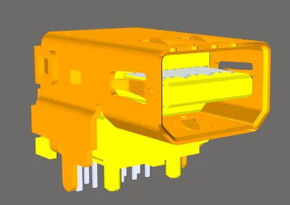
一个完成了3D实体的PCB组件印制板图。
3D实体是一种原始设计对象,用作容器,可以导入标准格式的通用3D模型,以表示安装在组装好的PCB上的物理组件的三维形状。当编辑器切换到3D显示模式时(点击查看 » 3D布局模式或按3快捷键),将显示实际的3D形状。
许多组件制造商和社区网站提供3D模型。支持以下文件格式:
- STEP –
*.Stp 和 *.Step
- SolidWorks 零件 –
*.SldPrt
- Parasolid 模型 –
*.x_t 和 *.x_b
放置 3D 实体对象以定义组件的形状,可以让你真实感受到组件在组装板上的排列。除了能够看到完成的板子会是什么样子,还可以进行实时的 3D 间隙检查,允许在设计阶段检测到组件与组件之间以及组件与外壳之间的碰撞。
3D 实体通常作为 PCB 脚印的一部分放置在 PCB 脚印编辑器中。脚印定义了连接点和组件占用的板面积,这是板设计所必需的最小要求。3D 实体是可选的;它可以添加到脚印上以定义安装在该脚印上的组件的外形尺寸。
3D 模型支持不仅限于组件。它还可以用来导入其他机械细节,如支架或成品外壳。直接将外壳导入到 PCB 编辑器中。
虽然使用通用3D模型是使用3D实体对象的推荐方式,因为这提供了PCB上准确和详细的组件表示,并且在PCB编辑器中提供了更准确的3D碰撞测试,但3D实体对象也可以用于放置挤出的多边形、圆柱形和球形3D实体形状,无论是在PCB编辑器中还是在PCB库组件的足迹中。有关使用这些对象的信息,请参见
在Altium Designer中使用挤出的、球形和圆柱形3D实体页面。
3D实体对象放置
通用模型,例如STEP格式的组件模型,是通过在3D实体对象中链接或嵌入来放置的。
要在PCB足迹或PCB文档内嵌入放置通用模型:
- 从主菜单选择放置» 3D实体命令,或使用活动栏上的3D实体命令(
 )。
)。
- 启动3D实体放置命令后,会出现标准Windows 打开对话框,在下拉菜单中选择所需的文件类型,然后浏览并定位所需的模型文件,点击打开。光标将变为十字形,选定的3D模型将浮动在其上。
- 按Tab键暂停放置,并在3D实体模式下显示属性面板。暂停按钮覆盖层(
 )将出现在设计空间中,表明您可以访问属性面板的字段。面板中将选择通用3D模型类型,以及嵌入模型作为3D实体源(意味着3D模型文件将嵌入到PCB库或PCB文件中)。
- 如果需要,可以覆盖默认模型颜色。在面板的显示部分,启用覆盖颜色复选框,然后根据需要设置颜色和不透明度。
- 面板编辑完成后,点击暂停按钮覆盖层返回到设计空间。
- 模型将浮动在光标上;定位它,然后点击放置。
- 软件的默认行为是保持在放置模式。如果需要,定位更多模型,或右键点击退出模型放置模式。
- 通用模型很可能需要重新定向;参考定向和定位3D模型部分,了解更多信息。
要放置使用除了
嵌入模型(
服务器或
链接到模型)之外的源的通用模型:
- 从主菜单选择放置» 拉伸3D实体命令,或点击活动栏上的
 图标。光标将变为十字形,您将进入默认的放置模式,放置一个拉伸3D实体对象。
- 按Tab键暂停放置,并在3D实体模式下显示属性面板。暂停按钮覆盖层()将出现在设计空间中,表明您可以访问属性面板的字段。
- 在属性面板的3D模型类型区域,点击通用按钮。
- 在属性面板的来源部分,点击设置来源为:
- 服务器 – 3D模型将从工作区检索。然后点击选择按钮打开选择项目对话框,在其中您可以访问连接的工作区中的内容。请参阅下面的引用基于工作区的3D模型部分以了解更多信息。
- 链接到模型 – 3D模型文件链接到PCB,此选项在PCB库编辑器中不可用。然后点击选择按钮打开
![]() 选择模型对话框,在其中您可以选择所需的模型。如果所需模型位置未在选择模型对话框中列出,请参阅下面的使用链接模型部分以了解更多信息。
选择模型对话框,在其中您可以选择所需的模型。如果所需模型位置未在选择模型对话框中列出,请参阅下面的使用链接模型部分以了解更多信息。
- 您将返回到属性面板,所选模型信息将被显示。
提供准确和详细的组件模型。
- 3D模型被导入到一个3D实体对象中。如果你在PCB库编辑器中点击选择一个MCAD模型,属性面板将显示包含该MCAD模型的3D实体对象的属性。
- 在放置3D实体之前,你可以为将包含3D实体的
3D Body类型分配一个组件层对。参考使用机械层页面了解更多关于机械层和组件层对的信息。
- 有多种选项可用于检查组件之间的间隙,包括一种模式,允许一个3D模型适配进另一个3D模型内。参考组件间隙设计规则了解更多信息。
如果在 PCB 或 PCB 脚印编辑器中看不到 3D 实体,请按
L 打开
查看配置面板,并确保在
查看选项标签页的
常规设置区域中将
显示 3D 实体选项设置为
开启(快捷键:
Shift+Z)。
使用链接模型
通常,此功能用于链接到大型的MCAD模型,例如您想要放置在PCB编辑器中以检查装载板是否适配的产品外壳。链接模型的优势在于,如果软件检测到外部链接的模型文件已更新,它将在文件打开时发出警告,允许刷新链接的模型。
链接的模型必须存储在在PCB编辑器 - 模型页面的首选项对话框中定义的位置。如果在选择模型对话框中未列出所需位置,请点击添加目录按钮以打开首选项对话框。
要在PCB编辑器 - 模型首选项页面中添加新位置:
- 要么输入完整路径,要么点击模型搜索路径字段右侧的按钮(
 )打开Windows浏览文件夹对话框。
- 在定位到所需文件夹并在对话框中点击确定后,你将返回到首选项对话框。点击添加按钮,将此位置包含在可用模型搜索路径的列表中。
- 请注意,只有指定的文件夹会被搜索模型文件;子文件夹不会被搜索。
- 一旦指定了所需位置,点击确定关闭首选项对话框并返回到选择模型对话框。
引用基于工作区的3D模型
要引用存储在连接的工作区中的3D模型:
- 在3D Body模式的Source区域选择服务器。
- 点击Item Revision字段右侧的选择按钮。
- 选择项目对话框将打开;使用此对话框浏览并选择所需工作区3D模型的修订版。
- 点击确定后,将在3D Body和目标工作区3D模型的修订版之间创建链接。在属性面板中可以看到此链接的证据。注意,3D体的标识符字段将填充为链接的工作区3D模型的项目-修订ID。
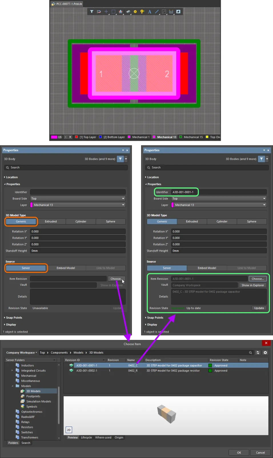
将3D实体对象链接到工作区3D模型的修订版
图形编辑
图形编辑方法允许您直接在设计空间中选择一个放置的3D体对象,并以图形方式更改其位置。
点击3D体,然后拖动以重新定位。拖动时,可以旋转或镜像3D体:
- 按空格键使3D体逆时针旋转,或按Shift+空格键使其顺时针旋转。旋转步长大小在PCB编辑器 – 通用页面的首选项对话框中定义。
- 按X键或Y键沿X轴或Y轴镜像3D体。
非图形编辑
这种编辑方法使用关联的属性面板模式来修改3D实体对象的属性。

属性面板的3D实体模式。
位置
此区域右侧的

(锁定)图标必须显示为

(解锁)才能访问下面的字段。切换锁定/解锁图标以更改其锁定状态。
- (X/Y)
- X(第一个字段)- 3D实体参考点的当前X(水平)坐标,相对于当前设计空间原点。编辑以更改3D实体的X位置。值可以以公制或英制输入,输入非当前默认单位的值时请包括单位。
- Y(第二个字段)- 3D实体参考点的当前Y(垂直)坐标,相对于当前原点。编辑以更改3D实体的Y位置。值可以以公制或英制输入,输入非当前默认单位的值时请包括单位。
属性
- 组件 - 仅当选中的3D实体是PCB组件的组成部分时,在PCB编辑器中显示此字段,并显示父PCB组件的指示器。选择可点击的组件链接以打开父组件的属性面板的组件模式。
- 标识符 - 输入用于识别3D实体对象的人类可读名称。标识符对于在PCB面板中选择3D实体很有用。
- 板侧 - 使用下拉菜单选择3D实体将从哪一侧的板上突出。如果3D实体对象作为组件翻转到板的另一侧,此设置将自动更改。
- 层 - 使用下拉菜单选择3D实体存在的层。仅可用当前启用的层。如果选择的层是配对的,则当实体作为其组件的一部分翻转到板的另一侧时,它也将移动到配对的层。
3D模型类型
从可用选项中选择3D实体对象的模型类型:通用、挤出、圆柱或球体。每种类型的选项不同,并提供在3D设计空间中调整大小和定位所需的控件。
- 通用 - 选择此选项时,3D实体对象充当其容器,并自动调整大小以包含所选模型。
- 旋转X° - 3D模型绕X轴的角度旋转(以度为单位)。点击 +/- 按钮以90°
增量更改角度旋转或手动输入值。
- 旋转Y° - 3D模型绕Y轴的角度旋转(以度为单位)。点击 +/- 按钮以90°
增量更改角度旋转或手动输入值。
- 旋转Z° - 3D模型绕Z轴的角度旋转(以度为单位)。点击 +/- 按钮以90°
增量更改角度旋转或手动输入值。
- 支撑高度 - 从板面到3D模型底部的距离。点击 +/- 按钮增加或减少值,或手动输入值。对于必须穿过PCB的模型,请使用负值。
- 来源
- 服务器
- 项目修订版 - 所需3D模型项目的修订版。点击项目修订版字段右侧的选择按钮以打开选择项目对话框。使用此对话框浏览并选择所需的修订版。点击确定后,将在3D实体和目标3D模型项目修订版之间创建链接。
- 库 - 显示目标服务器。使用在资源管理器中显示按钮打开资源管理器面板。
- 详情 - 显示修订详情。
- 修订状态 - 显示链接的3D模型项目的状态。
- 更新 - 如果链接的项目有更新的修订版可用,点击以使用最新的修订版。
- 嵌入模型 - 用于选择要嵌入的3D模型(STEP, Parasolid, SolidWorks部件)。
- 链接到模型 - 用于链接到3D模型。
- 路径 - 点击选择搜索并选择模型的路径。点击
 刷新路径。
刷新路径。
- 挤出
- 整体高度 - 从板面到挤出体顶部的距离。
- 支撑高度 - 从板面到挤出体底部的距离。点击 +/- 按钮增加或减少值,或手动输入值。对于必须穿过PCB的挤出体,请使用负值。
- 纹理
- 纹理文件 - 定义要显示在挤出体顶部表面的图像。接受的文件格式有
*.bmp、*.dds、*.dib、*.hdr、*.jpg、*.pfm、*.png、*.ppm和*.tga。点击
