
Altium Designer でのボード設計における機械層の取り扱い
最もシンプルな基板であっても、回路を実装するトラックやパッド以外に、設計の詳細が必要です。それは基板の寸法や製造の詳細かもしれませんし、コンポーネントのコートヤードや3Dコンポーネントモデルかもしれません。Altium Designerでは、このような追加情報は機械層に詳細が記載されます。
機械層を使用する方法は2つあります。それは:
- 基板のアウトラインなど、特定の基板の面に適用されないタスクに使用される個別の機械層、または
- コンポーネントのコートヤードなど、特定の面に適用される詳細に対して、一対の層として。コンポーネント関連の詳細に対してペアが使用されるため、これらはコンポーネント層ペアと呼ばれます。
これらの個別/層ペアは、必要に応じて印刷物や製造出力に含めることができます。
設計に機械層を追加する
機械層はView Configurationパネルで追加、編集、削除されます。その表示状態もパネルで設定されます。デザインスペースの右下にある![]() ボタンを使用してView Configurationを選択するか、Lショートカットキーを押してパネルを表示します。
ボタンを使用してView Configurationを選択するか、Lショートカットキーを押してパネルを表示します。
パネルのLayers領域のどこかを右クリックすると、コンテキストメニューが表示され、Add Component Layer Pair(2つの機械層のペアリング)およびAdd Mechanical Layerのコマンドが提供されます。

コンポーネント層ペアまたは機械層の設定は、Edit Layers Pair / Edit Layerダイアログを使用して行われます。このダイアログを使用してLayer Pair Name / Layer Nameを入力し、Layer Number(s)を定義し、層タイプを割り当てます。


-
コンポーネント層ペアまたは機械層が追加されたとき、Layer Pair Name / Layer Nameが編集されない場合、ソフトウェアは割り当てられたLayer Typeに基づいて名前を自動的に定義します。
-
Layer Pair Name / Layer Nameが改名されると、Layer Typeがユーザー定義の名前の隣に括弧内に表示されます(View Configurationパネル上)。
-
Layer Number(s)を指定する際、希望する層番号が既に使用されている場合は、選択した層番号の隣に警告アイコンが表示され(例:
 )、別の層番号を割り当てる必要があります。
既存のコンポーネント層ペアまたは機械層を編集するには、View Configurationパネルのそのエントリを直接ダブルクリックするか(または、希望するエントリを右クリックしてコンテキストメニューからEdit Layerを選択します)。必要に応じてEdit Layers Pair / Edit Layerダイアログで変更を加えます。
層を削除するには、希望する層を右クリックしてDelete Layerを選択します。層の使用方法によっては、次の3つのオプションが表示されます:
-
層が削除できない場合(削除できないコンポーネントプリミティブが含まれている場合)、エラーポップアップが表示され、アクションを完了できないことを警告します。
-
層が削除できるプリミティブと関連付けられている場合、削除の確認を求めるポップアップが表示されます。
-
層がプリミティブと関連付けられていない場合、Delete Layerをクリックすると、確認なしに直ちに削除されます。
層タイプ
コンポーネントレイヤーペアと個々のメカニカルレイヤーの2つのレイヤータイプのセットがあります。レイヤータイプは、Edit LayerダイアログのLayer Typeドロップダウンを使用して設定されます。利用可能なレイヤータイプは以下の通りです。
コンポーネントレイヤーペア
-
Assembly - コンポーネントの組み立てデータを描画/詳細に使用されます。このレイヤーはドラフトマンボードアセンブリビューに含めることができ、ドラフトマンのコンポーネント表示プロパティダイアログでコンポーネントのGeometry Sourceとして選択できます。ドラフトマンについてもっと学ぶ。
-
Coating - 保護コーティングが必要なコンポーネント領域を定義するために使用されます。
-
Component Center - コンポーネントの重心を示し、組み立て文書内のコンポーネント配置機械が使用する位置の視覚的な参照を提供します。
-
Component Outline - コンポーネント本体のアウトラインを定義し、ボード上でコンポーネントが占める領域を表します。
-
Courtyard - コンポーネントに必要な配置スペースを定義します。通常、コートヤードはコンポーネントとパッドをアウトラインし、適切なクリアランスバッファーを持ちます(画像を表示 - 緑のアウトラインがコートヤードです)。カスタムフットプリント作成についてもっと学ぶ。コートヤードレイヤーで定義された形状は、コンポーネント選択、コンポーネント領域の定義、およびコンポーネントに3Dボディが含まれていない場合の衝突検出にも使用されます。
-
Designator -
.Designator特別な文字列を配置するためにこのレイヤーを使用します。このレイヤーペアは、コンポーネントのデザインエータを表示する必要がある組み立て図面に含めることができます。特別な文字列についてもっと学ぶ。 -
Dimensions - コンポーネントに必要な寸法の詳細を定義するために使用されます。
-
Glue Points - コンポーネントのグルードットを定義するために使用されます。
-
Gold Plating - コンポーネントの選択的な金メッキ要件を定義するために使用されます。
-
Value -
.Comment特別な文字列を配置するためにこのレイヤーを使用します。このレイヤーペアは、コンポーネントの値を表示する必要がある組み立て図面に含めることができます。特別な文字列についてもっと学ぶ。 -
3D Body - コンポーネントの3Dモデル用にこのレイヤーを使用します。
-
Die - チップオンボードコンポーネントを作成する際のダイパッドとダイ3Dボディ用にこのレイヤーを使用します。ワイヤーボンディングページを参照してもっと学ぶ。
-
Wire Bonding - チップオンボードコンポーネントを作成する際、またはPCBドキュメント内で直接、ボンドワイヤー用にこのレイヤーを使用します。ワイヤーボンディングページを参照してもっと学ぶ。

メカニカルレイヤー
-
Assembly Notes - コンポーネントのロード順序および/または重要な組み立て指示の詳細に使用されます。
-
Board - ボード関連の指示または詳細にこのレイヤーを使用します。
-
Board Shape - 全体のボードアウトライン(ボード形状)にこのレイヤーを使用します。
-
Route Tool Path - 機械的なルーティング情報を含むレイヤーを示すために使用します。このレイヤータイプを使用する場合、ユーザー定義の名前は許可されていません(画像を表示)。
-
Sheet - このレイヤーを使用して、外部ドキュメントの図面テンプレートの境界を定義します。下記のシート表現と設定セクションで詳細を確認してください。
-
V Cut - Vカットの詳細を定義するために使用します。Vカットは、基板の上部と下部に「v」の溝を切り、基板のパネルを一緒に保持するために最小限の材料を残すことによって、回路基板を分割するために使用されます。
機械レイヤーの表示
-
レイヤー名の横にある表示アイコン(
 )をクリックして、その機械レイヤーの表示をオンまたはオフに切り替えるか、レイヤー名を選択してSpacebarを押します(これにより、コンポーネントレイヤーペアの両方のレイヤーの表示が切り替わります)。
-
機械レイヤーには、シングルレイヤーモードでの表示が有効になっている場合に表示されるという追加の表示機能があります。機械レイヤーの表示アイコンをCtrlを押しながらクリックして、Display in Single Layer Mode機能を有効にします。表示アイコンがこのレイヤーにこの機能が有効であることを示すように変わります(
 )、Ctrl+クリックをもう一度行うとこのモードが無効になります。
-
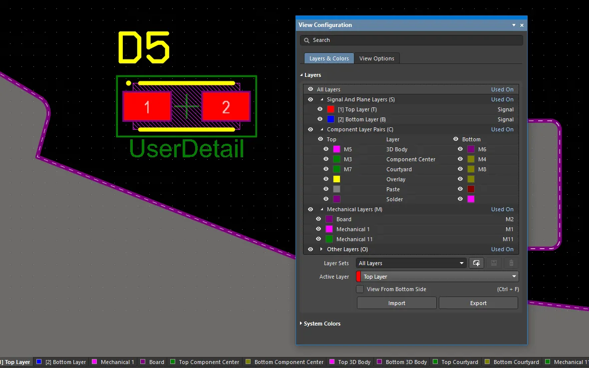
機械レイヤーは、3D設定がColors - By Layerを使用している場合、3D表示にも含まれます。現在表示に設定されている機械レイヤーが、下の画像に示されているように表示されます。以下のスライドショーの2番目の画像は、ビューオプション設定を示しています。


機械レイヤーのエクスポートとインポート
PCBに追加された機械レイヤーとコンポーネントレイヤーペアの構造は、ソースPCBドキュメントからそのセットをファイルにエクスポートし、そのファイルをターゲットPCBドキュメントにインポートすることによって、別のPCBに複製することができます。
-
必要な機械レイヤーとコンポーネントレイヤーペアの構造が追加されたソースPCBドキュメントでは、メインメニューからTools » Export Mechanical Layersコマンドを使用します。開いたExport Mechanical Layersダイアログで、機械レイヤー構造に関するデータを含む
*.stackupファイルの名前とディレクトリを定義します。 -
ターゲットPCBドキュメントでは、メインメニューからTools » Import Mechanical Layersコマンドを使用し、開いたImport Mechanical Layersダイアログで、保存された
*.stackupファイルを選択します。追加された機械レイヤーとコンポーネントレイヤーペアの構造は、View Configurationパネルで確認できます。
機械層とコンポーネント層ペア
ある状況では、機械層に含まれる追加の詳細が一度だけ必要になることがあります。例えば、コンポーネントの積載順序と重要な組み立て指示を詳述する組み立てノートです。この状況では、標準の機械層が追加され、名前が付けられ、可能であればそのレイヤータイプが割り当てられます(以下で詳述)。
コンポーネントに追加の詳細が必要な場合、例えば、コンポーネントのコートヤードのアウトラインの場合、2つの機械層が割り当てられる必要があります:一つはコンポーネントがボードの表側に配置されたときにコートヤードの詳細を保持する層、もう一つはコンポーネントがボードの裏側にフリップされた場合に同じコートヤードの詳細を保持する機械層です。
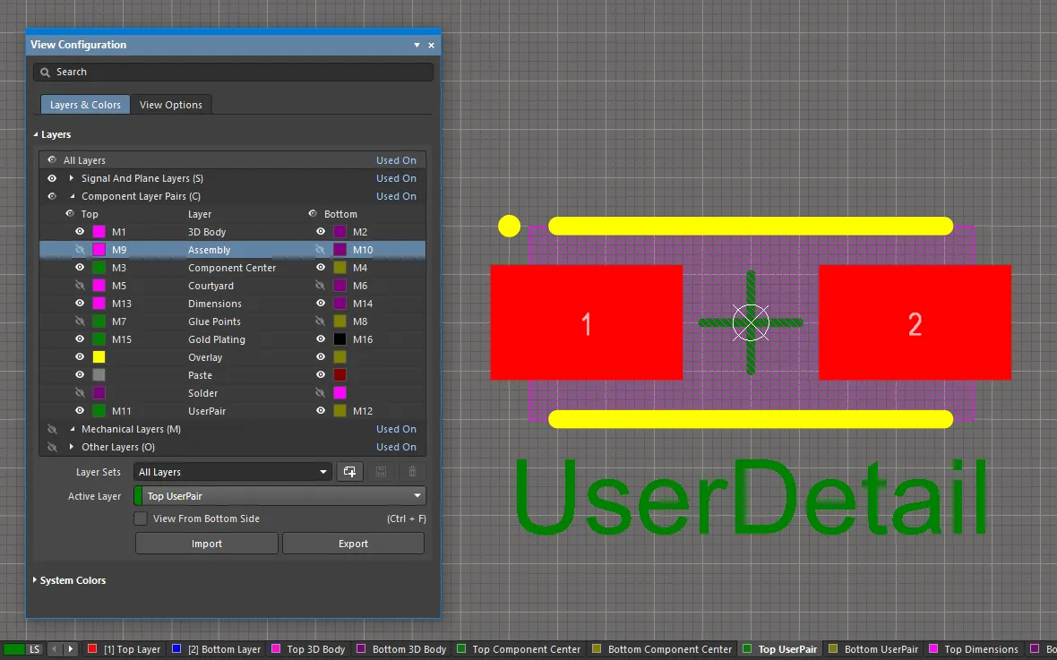
この状況では、コンポーネント層ペアとして一対の機械層が追加されます。機械層がコンポーネント層ペアとして追加されると、以下に示すようにView ConfigurationパネルのComponent Layer Pairsセクションに表示されます。

ユーザー定義のコンポーネント層ペアがいくつか追加されました。
-
任意の数のコンポーネント層ペアを定義できます。
-
層ペアにはレイヤータイプも割り当てることができます。
-
設計スペースでは、ペア内の2つの層がTop <LayerPairName>およびBottom <LayerPairName>(画像を表示)という名前で別々のレイヤータブに表示されます。
-
PCBライブラリエディタでは、コンポーネントフットプリントに必要な追加の設計オブジェクトが上部ペア層に配置されます。コンポーネントがボードの裏側にフリップされると(L ショートカットを使用してコンポーネントを移動中)、ペア内の上層の内容が自動的に下層にミラーリングされます。
-
PCBライブラリで定義されたコンポーネント層ペアにレイヤータイプが割り当てられている場合、その層を使用するコンポーネントが配置されると、そのレイヤーペアはPCB上に自動的に作成されます。PCBにそのレイヤータイプのコンポーネント層ペアが既にある場合、それらの層の内容は適切にマッピングされます。
-
ライブラリでレイヤータイプが割り当てられていないPCBライブラリで定義されたコンポーネント層ペアの場合、個々の機械層がPCB上に作成されます。この状況では、コンポーネントを配置する前にPCBでコンポーネント層ペアを同じレイヤー番号を使用して事前に定義します。ソフトウェアがレイヤータイプでのマッチングに失敗した場合、レイヤー番号でのマッチングにフォールバックします。

レイヤータイプを割り当てる利点
機械層の使用を管理する一般的なアプローチは、必要な機械層機能ごとに専用のレイヤー番号を割り当てることです。このアプローチは、すべての設計者が同じレイヤー割り当ておよび番号付けスキームに従うことを要求します。また、同じ割り当ておよび番号付けスキームに従わない他のソースからコンポーネントを取得した場合、問題を引き起こす可能性があります。異なるスキームが使用されている場合、設計オブジェクトは現在の機械層からその機能に割り当てられた機械層に移動する必要があります。
Layer Typeプロパティの導入により、この問題が解決されます。コンポーネントがライブラリからPCBエディタに配置されるか、あるいはライブラリ間でコピーされるか、またはIPC Footprint Wizardによって作成された場合、既存のレイヤータイプ割り当ては、それらのレイヤータイプに割り当てられた機械層番号に関係なく自動的にマッチングされます。オブジェクトは、そのレイヤータイプに従って正しい層に配置されます。ソフトウェアがレイヤータイプでマッチングできない場合、レイヤー番号でのマッチングにフォールバックします。
個々の 機械レイヤーと構成部品レイヤーペアの両方で、定義済みのタイプのリストからレイヤータイプを選択できます。以下の画像は、使用可能なレイヤー タイプのリストを示しています。以下に示すダイアログにアクセスするには、個々のレイヤーを右クリックし、メニューからEdit LayerまたはAdd Component Layerコマンドを選択します。
 事前定義されたタイプのリストからレイヤータイプを選択します。個々の機械レイヤーは左側に示されています。コンポーネントレイヤーペアが中央に表示され、新しいコンポーネントレイヤーが右側に表示されます。
レイヤータイプが割り当てられたレイヤーの命名
レイヤータイプが割り当てられると、レイヤーの名前プロパティは自動的にレイヤータイプと同じ名前に変更されます。必要に応じて、ユーザー定義の名前を入力して上書きすることができます。レイヤーにユーザー定義の名前とレイヤータイプが割り当てられている場合、両方が表示され、レイヤータイプは括弧内に表示されます。以下のレイヤーペアGP (Gold Plating)のように表示されます。

ルートツールパスレイヤータイプ
レイヤータイプが割り当てられた場合の命名動作には一つ例外があります - Layer TypeがRoute Tool Pathに設定されている場合、ユーザー定義の名前は許可されません。これは、ソフトウェアの古いバージョンがルート情報(ルート情報とも呼ばれる)を含むレイヤーを識別するためにルートツールパスレイヤーの名前を使用するためです。このレイヤーの命名を固定することで、古いバージョンでも設計が正しく機能し続けることが保証されます。
ルートツールパスレイヤータイプは、機械的なルーティング情報を含むレイヤーを示すために使用されます。このレイヤーを使用する一般的なアプローチは、ボードの形状の外側にトラックとアークを配置して加工パスと幅を定義し、ボードをパネル内で保持するために固体部分を残し、その後、各固体部分に小さな穴を配置して穿孔(通常はマウスバイトと呼ばれる)を作り、組み立てプロセスが完了したらボードをパネルから抜き出せるようにします。
ボードが3Dモードで表示されると、ルートツールパスレイヤー上で検出されたオブジェクトは、以下に示すように、ボードのルーティングスロットとして表示されます。

ルートツールパスレイヤー上で検出されたオブジェクトは、3D表示モードでルーティングされたボードを視覚化するために使用されます。
Line/Arc Primitives from Board Shapeダイアログを使用して、ボード形状の外側をトラックとアークでトレースします。Route Tool Outlineオプションをダイアログで有効にすると、オブジェクトがボード形状の端に沿って中央に配置されるのではなく、ボード形状の外側に配置されます。一部の設計者は、実際のボードファイルにこの詳細を含めるのではなく、埋め込みボードアレイ機能を使用して組み立てパネルを作成するときに製造情報を追加することを好みます。

► ボードパネル化とルートツールパスの定義についてもっと学ぶ
番号付き機械レイヤーからレイヤータイプへの移行
可能な限り、ソースライブラリを編集してレイヤータイプを割り当てることを推奨します。コンポーネントのフットプリントがライブラリから配置(またはコピー)されると、それらのレイヤータイプの機械レイヤーやコンポーネントレイヤーペアは、対象のボード(またはライブラリ)に存在しない場合、自動的に作成されます。それらのレイヤータイプが対象のボード(またはライブラリ)に既に存在する場合、レイヤーの内容は自動的に正しいレイヤーにマッピングされます。
|
レイヤータイプが割り当てられたユーザーレイヤーは、コンポーネントがボードに配置されると自動的に作成またはマッピングされます。 ボード上のコンポーネント。 |
シートプレゼンテーションと設定
Sheetタイプの機械レイヤーを追加して、外部ドキュメント描画テンプレートの境界を定義します。

Sheet Settingsは、そのPropertiesパネルのBoardモードでカスタマイズできます。シートの左下隅のX/Y値、Width、およびHeightに関してです。 Get Size From Sheet Layerオプションが有効になっている場合、シートの背景はSheet機械レイヤーに配置されたオブジェクトのセットの境界矩形から自動的に計算されます。

シートの背景の色と表示設定はView ConfigurationパネルのSystem Colorsセクションで設定します。色ボタンをクリックして、Sheet LineとArea Colorを変更します。 ![]() /
/![]() でシートの表示/非表示を切り替えます。
でシートの表示/非表示を切り替えます。

出力へのメカニカルレイヤーの組み込み
メカニカルレイヤーは、ボードの設計、製造、組み立て、および製品文書化中に使用される詳細な情報を含む、さまざまなタスクに使用されます。これらすべての要件をサポートするために、印刷や出力ファイルの生成など、あらゆる形式のレイヤーベースの出力生成でメカニカルレイヤーを除外または含めることができます。
印刷出力
設計に存在するレイヤーは、機械層を含むすべて、PCB印刷の仕様に含めることができます。印刷物は、必要なレイヤーを追加し、Printダイアログでその順序を設定することによって構成されます。

機械層にオブジェクトを配置することで、非常に詳細な製造および組立図面を作成することができます。
►2D印刷ベースのPCB出力の準備についてもっと知る
生成された出力
GerberやODB++などの製造タイプの出力は、機械層をプロットする出力レイヤーとして含めることができるほか、プロットされるすべてのレイヤーに詳細を追加することもできます。出力は、OutputJob設定ファイル(*.OutJob)でODB出力ジェネレータを使用して設定された出力ジェネレータが実行されると生成されます。

機械層はプロットされることも、必要に応じてすべてのプロットに追加されることもあります。
►製造のためのデザインの準備についてもっと知る