회로도는 단순한 그림 그 이상으로, 회로의 전기적 연결(Connectivity) 정보를 담고 있습니다. 이러한 연결 인지 기능을 활용해 설계를 검증할 수 있습니다.
회로도 검증 및 검증 옵션 구성
설계를 검증하려면 메인 Project 메뉴에서 Validate PCB Project <ProjectName> 명령을 선택합니다. Projects 패널에서 포커스된 프로젝트를 검증하려면, 프로젝트 항목을 마우스 오른쪽 버튼으로 클릭했을 때의 메뉴에서 Validate Project 명령을 사용하거나, 패널 상단의  컨트롤을 사용할 수도 있습니다.

Validate PCB Project <ProjectName> 명령을 사용해 설계를 검증합니다.
소프트웨어는 Unified Data Model과 프로젝트 검사 설정 간의 논리적, 전기적, 드래프팅(도면) 오류를 확인합니다. 회로도에 검증 오류 및 경고를 표시하도록 설정되어 있으면(Preferences 대화상자의 Schematic – Compiler page에서 활성화), 문제가 있는 객체 아래에 색상 물결선이 표시됩니다. 객체 위에 마우스를 올리면 위반 내용을 요약한 팝업 힌트가 표시됩니다. 또한 Messages 패널에도 알림이 표시됩니다.
객체 힌트(
Mouse Hover 및/또는
Alt+Double Click)의 표시(실행) 방식을 결정하려면,
Preferences 대화상자의
System – Design Insight page에 있는
Connectivity Insight Options 영역의
Object Hints 항목과 관련된 컨트롤을 사용합니다.
검증된 설계에 대해 수행할 수 있는 드래프팅 및 전기적 체크 항목은 매우 많습니다. 이는 프로젝트 옵션의 일부로 구성됩니다. 메인 메뉴에서 Project » Project Options 명령을 선택하여 Project Options 대화상자를 여십시오. 기본 설정은 모든 설계에 적합하지 않으므로, 옵션과 이를 설계에 맞게 구성하는 방법을 숙지하는 것이 중요합니다.
Workspace 프로젝트로 작업할 때는 Workspace의 Web Viewer에 현재 프로젝트에 대한 Electrical Rule Check 보고서가 포함되어 있다는 점에 유의하십시오. 이를 통해 Altium Designer에서 설계를 열지 않고도 ERC 위반 사항을 편리하게 검토할 수 있습니다. Web Viewer의 DRC 및 ERC 보고서에 대해 더 알아보기(
Altium 365 Workspace,
Enterprise Server Workspace).
드래프팅 체크
검증 중에는 Project Options 대화상자의 Error Reporting tab 설정에 따라 일반적인 드래프팅 및 편집 오류가 검사됩니다. 오류 체크는 예를 들어 Violations Associated with Nets, Violations Associated with Components 등과 같이 그룹으로 구성됩니다. 그룹은 대화상자에서 알파벳순으로 나열됩니다. 각 위반 항목의 Report Mode은 클릭한 뒤 드롭다운에서 원하는 값을 선택하여 네 가지 값 중 하나로 변경할 수 있습니다.

Project Options 대화상자의 Error Reporting 탭에서 필요한 오류 체크를 구성합니다. 특정 위반 항목에 대해 변경하려면 해당 위반의 Report Mode 셀을 클릭하십시오.
일반적으로는 먼저 기본 설정으로 설계를 검증하고 경고를 확인하는 것이 좋습니다. 현재 설계에서 문제가 되지 않는 경고에 대해서는 보고 레벨을 변경할 수 있습니다.
각 오류 체크에 대한 자세한 정보는 아래의 PCB Design Violation Types 섹션을 참조하십시오.
연결성 체크
전기적 연결성은 Project Options 대화상자의 Connection Matrix tab 설정에 따라 검사됩니다.

Connection Matrix는 어떤 전기적 조건이 허용되는지, 어떤 조건이 허용되지 않는지를 정의합니다.
이 매트릭스는 컴포넌트 핀과 Port, Sheet Entry 같은 넷 식별자 간의 연결 규칙을 설정하는 메커니즘을 제공합니다. 또한 경고 또는 오류로 보고할 논리적/전기적 조건을 정의합니다. 예를 들어 출력 핀이 다른 출력 핀에 연결되는 것은 일반적으로 오류로 간주되지만, 서로 연결된 두 개의 패시브 핀은 그렇지 않습니다.
매트릭스의 작은 사각형을 클릭하여 특정 규칙을 변경합니다. 각 규칙은 주어진 핀/넷 식별자 조합에 대한 보고 레벨을 결정합니다. 각 규칙에는 Fatal Error, Error, Warning, No Report의 네 가지 가능한 값이 있습니다.
Error Reporting 및 Connection Matrix 설정은 현재 프로젝트의 요구사항에 맞게 검토하고 설정해야 합니다.
메시지 해석 및 오류 위치 찾기
프로젝트를 검증하면 경고 또는 오류를 생성하는 모든 조건이 Messages 패널에 나열됩니다. Messages 패널은 Error 또는 Fatal Error 조건이 하나 이상 있을 때만 자동으로 열린다는 점에 유의하십시오. Warning를 확인하려면, 디자인 스페이스 오른쪽 하단의 Panels 버튼을 클릭한 다음 Messages를 선택하여 패널을 수동으로 열어야 합니다. 프로젝트가 검증되면 패널에 감지된 모든 경고와 오류가 표시됩니다.

Messages 패널에는 프로젝트에서 감지된 경고와 오류가 표시됩니다.
Messages 패널은 위반 사항을 표시하는 ‘중앙 제어’ 역할을 합니다. 알아두어야 할 사항은 다음과 같습니다.
-
Messages 패널은 두 개의 영역으로 구성됩니다. 상단 그리드 영역은 경고/오류를 요약하고, 하단 영역은 현재 선택된 경고/오류의 세부 정보를 제공합니다.
-
메시지를 더블클릭하면 해당 경고/오류 위치로 크로스 프로빙됩니다. 세부 항목을 더블클릭하면 해당 특정 객체가 표시됩니다.
Messages 패널에서 오류를 더블클릭하면:
-
회로도가 확대/이동되어 오류 객체가 보이도록 표시됩니다. Zoom Precision 은 Preferences 대화상자의 System – Navigation page의 Highlight Methods 섹션 상단 슬라이더로 설정됩니다.
-
오류 객체를 제외한 회로도 전체가 페이드(흐리게) 처리됩니다. 회로도가 흐려지는 정도는 Preferences 대화상자의 System – Navigation page에 있는 Highlight Methods 섹션 하단 슬라이더로 설정되는 Dimming 레벨로 제어됩니다. 회로도 아무 곳이나 클릭하면 디밍이 해제됩니다.

-
Messages 패널의 열 머리글(예: Class, Document, Message)을 클릭하여 오류와 경고를 정렬하는 데 활용할 수 있습니다.
-
Messages 패널에서 마우스 오른쪽 버튼을 클릭한 다음 Group By 하위 메뉴 옵션을 사용하여 특정 기준으로 오류와 경고를 그룹화할 수 있습니다.
-
Messages 패널에서 마우스 오른쪽 버튼을 클릭한 다음 적절한 Clear 명령으로 메시지를 삭제하거나, Export To Report 명령으로 메시지를 보고서로 내보낼 수 있습니다.
메시지를 지운다고 해서 반드시 문제가 해결된 것은 아닙니다. 해결되지 않은 동일한 메시지는 다시 검증을 수행하면 다시 나열됩니다. 메시지 삭제는 설계 오류를 해결하는 과정에서, 해결되었다고 판단되는 메시지를 사용자가 수동으로 제거할 수 있게 해주는 시각적 보조 기능입니다. 남아 있는 위반 사항의 최신 상태를 확인하려면 검증을 다시 실행해야 합니다.
-
이 패널에는 Error Reporting 탭과 Connection Matrix 탭의 설정에서 감지된 경고와 오류가 모두 포함됩니다.
-
Messages 패널에서 경고/오류를 마우스 오른쪽 버튼으로 클릭한 다음 Place Specific No ERC for this violation 명령을 선택하면, 오류 위치로 자동 크로스 프로빙되며 커서에 No ERC 지시자가 나타나 해당 오류 위치에 배치하여 오류 검사를 억제할 수 있습니다. 자세한 내용은 Suppressing ERC Violations를 참조하십시오.
경고 또는 오류 해결
감지된 각 경고 또는 오류를 처리하는 것이 중요합니다. 기본 오류 설정은 보수적인 편인데, 이는 소프트웨어가 신중한 쪽으로 판단하고 사용자가 테스트 경계를 완화할지 여부를 결정하도록 하는 것이 더 낫기 때문입니다. 예를 들어 설계에서 IO 핀이 Input 포트에 연결되어야 할 수 있으며, 이 경우 Connection Matrix 탭에서 해당 셀을 조정해야 합니다. 또 다른 흔히 변경되는 오류 체크는 Nets with no driving source로, Error Reporting 탭에서 해당 체크를 비활성화해야 할 수 있습니다.
설계 전체에 대해 특정 조건을 검사하되, 회로의 특정 지점에서 발생하는 경고/오류는 무시하고 싶은 경우가 있습니다. 예를 들어 특정 위치에서만 넷 이름 변경을 허용하고 싶을 수 있습니다. 이는 해당 위치에 No ERC 지시자를 배치하여 수행할 수 있습니다.
ERC 위반 억제
회로의 특정 지점에서 오류가 보고되지 않도록 허용해야 할 때는, 그 지점에 No ERC(Electrical Rules Check) 지시자를 배치하여 do not flag a warning/error at this location를 의미하도록 합니다. No ERC 지시자는 (연결되지 않은 핀처럼) 경고를 발생시킬 것이 확실한 회로의 특정 지점에서 의도적으로 오류 검사를 제한하면서도, 회로의 나머지 부분에 대해서는 포괄적인 검사를 수행할 수 있게 해줍니다.
No ERC 지시자는 여러 가지 스타일을 지원하며 어떤 색상으로도 표시할 수 있습니다. 이 기능을 활용해 해당 회로 지점의 설계 의도를 반영하십시오.

해당 회로 지점에서의 기능을 가장 잘 반영하는 No ERC 스타일을 선택하십시오.
No ERC 지시자는 두 가지 동작 모드를 가집니다.
-
Suppress All Violations – 이 모드에서는 가능한 모든 경고 및/또는 오류 조건이 억제됩니다. 이 모드에서는 해당 지시자를 흔히 Generic No ERC 지시자라고 부릅니다.
-
Suppress Specific Violations – 이 모드에서는 선택된 경고 또는 오류 조건만 억제되며, 그 외의 경고나 오류는 감지되어 보고됩니다. 이 모드에서는 해당 지시자를 흔히 Specific No ERC 지시자라고 부릅니다.
억제된 위반 사항은
Project Options dialog의
Error Reporting tab에 있는
Report Suppressed Errors in Messages Panel 옵션을 활성화하면
Messages panel에 표시할 수 있습니다. 이 기능은 설계의 최종 단계에서 중요한 오류가 실수로 억제되지 않았는지 확인하는 데 사용할 수 있습니다.
No ERC 지시문은 모든 유형의 오류 검사를 억제하는 데 사용할 수 없다는 점에 유의하십시오.
No ERC dialog가
Violation Types mode에 있을 때, 억제할 수 있는 위반 유형 목록이 표시됩니다. 이를 참고하여 어떤 오류 테스트를 억제할 수 있는지 확인하십시오.
사용 예
‘구동 소스가 없는(net not having a driving source)’ 넷에 대한 경고를 접했지만, 확인해 보니 해당 메시지는 안전하게 무시해도 되는 경우가 얼마나 많았나요? 예를 들어 입력 핀이 커넥터로부터 신호를 받는데, 그 커넥터 핀은 명목상 패시브이고 외부 케이블이 연결될 때만 구동 신호가 존재하는 경우가 있을 수 있습니다. 또는 넷이 풀업 저항이나 스위치에서 나오는데, 이들 역시 본질적으로 패시브일 수 있습니다. 이 경고를 해결하기 위해 다음 전략 중 하나를 채택할 수 있습니다.
No ERC 지시문 배치하기
No ERC 지시문은 여러 방법으로 회로도 문서에 배치할 수 있습니다.
-
메인 메뉴에서 Place » Directives » Generic No ERC command를 선택하거나, Wiring toolbar의
 button을 클릭하거나, 설계 공간에서 마우스 오른쪽 버튼을 클릭한 뒤 Place » Directives » Generic No ERC command를 선택하여 일반(Generic) No ERC 지시문을 배치할 수 있습니다.
-
이미 위반이 표시되고 있는 회로의 지점에 특정(Specific) No ERC 지시문을 배치하려면, 설계 공간에서 위반 객체(물결 모양의 색상 선으로 강조 표시됨) 위에서 마우스 오른쪽 버튼을 클릭하고 컨텍스트 메뉴에서 Place NoERC to Suppress command를 선택하십시오.

오른쪽 클릭 컨텍스트 메뉴를 사용하여 특정 No ERC 지시문을 배치합니다.
-
또는 Messages panel에서 경고/오류를 마우스 오른쪽 버튼으로 클릭하고 Place Specific No ERC for this violation command를 선택한 다음, 회로도에서 해당 지점으로 바로 이동하여 그 경고/오류를 억제하도록 구성된 No ERC 지시문을 배치할 수 있습니다.

Messages panel의 오른쪽 클릭 컨텍스트 메뉴를 사용하여 특정 No ERC 지시문을 배치합니다.
이 command는 메시지가 넷 관련 컴파일러 위반(Net-related compiler violation)인 경우에만 사용할 수 있습니다.
No ERC 지시문 편집하기
배치 중이며 No ERC 객체가 아직 커서에 떠 있는 동안에는 다음 편집 작업을 수행할 수 있습니다.
-
Properties panel에서. 이 편집 방법은 연관된 Properties panel mode를 사용하여 객체의 속성을 수정합니다.

Properties panel의 No ERC mode
배치 중에는 Properties panel의 No ERC mode를 Tab key를 눌러 접근할 수 있습니다.
배치 후에는 Properties panel의 No ERC mode를 다음 방법 중 하나로 접근할 수 있습니다.
-
배치된 지시문을 더블 클릭합니다.
-
지시문 위에 커서를 올린 다음 마우스 오른쪽 버튼을 클릭하고 컨텍스트 메뉴에서 Properties 를 선택합니다.
-
Properties panel이 이미 활성화되어 있다면, 지시문을 선택합니다.
배치 모드로 들어가기 전에
Preferences dialog의
Schematic – Defaults page에서 속성에 접근할 수 있습니다. 이를 통해 객체의 기본 속성을 변경할 수 있으며, 이후 객체를 배치할 때 변경된 기본값이 적용됩니다.
-
No ERC dialog에서. 이 편집 방법은 No ERC dialog를 사용하여 Specific No ERC 객체의 위반 유형과 연결 오류를 수정합니다.
 and Connection Matrix mode (the second image)")
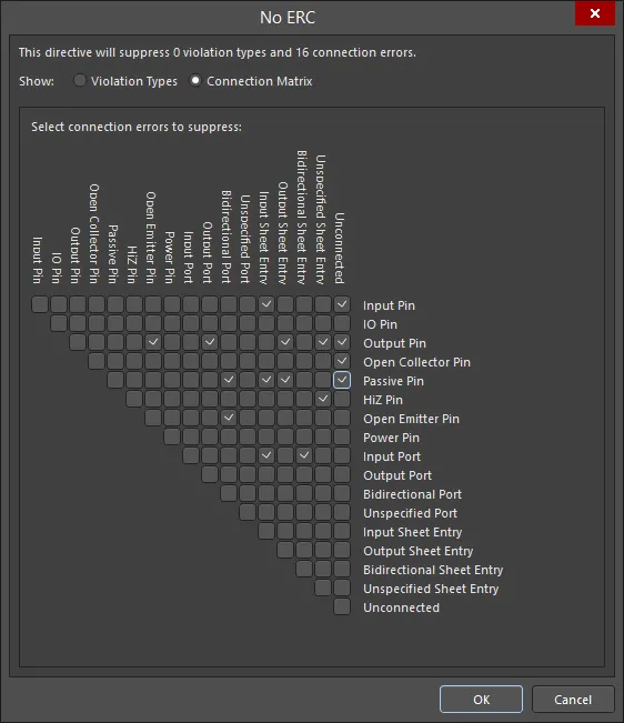
The No ERC dialog showing Violation Types mode (the first image) and Connection Matrix mode (the second image)
이 dialog는(위에서 언급한) No ERC mode에서 Properties panel의 Suppressed Violations region에 있는 Specific Violations를 클릭하여 접근할 수 있습니다.

Options and Controls of the No ERC Dialog
-
Top statement - 이 문구를 통해 현재 억제된 위반 유형과 연결 오류의 개수를 빠르게 확인할 수 있습니다. 이 문구는 dialog에서 변경을 수행할 때마다 업데이트됩니다.
-
Show - Violation Types 또는 Connection Matrix 중 하나를 선택하여 해당 No ERC 지시문을 보고 구성합니다.
위반 유형(Violation Types)
이 mode에서는 위반 유형을 억제/억제 해제할 수 있습니다.
-
Violation Type To Suppress - 구성 가능한 위반 유형 목록을 표시합니다.
-
Report Mode - 나열된 위반 유형에 대한 현재 보고 모드를 표시합니다.
-
Suppress - 체크박스를 선택하면 해당 위반 유형을 억제하고, 선택 해제하면 억제를 해제합니다.
오른쪽 클릭 메뉴
다음 오른쪽 클릭 메뉴 command에서 [xxx] 는 오른쪽 클릭을 수행할 때 선택되어 있었던(또는 커서가 올라가 있었던) 위반 유형에 따라 변경됩니다.
또한 Violations Associated with 항목을 오른쪽 클릭하여 해당 객체 전체에 대한 오른쪽 클릭 메뉴 command에 접근할 수도 있습니다.
-
Suppress only "[xxx]" - 따옴표 안에 나열된 위반 유형만 억제하는 데 사용합니다.
-
Unsuppress only "[xxx]" - 따옴표 안에 나열된 위반 유형만 억제 해제하는 데 사용합니다.
-
Suppress All "[xxx]" - 따옴표 안에 나열된 객체의 모든 위반 유형을 억제하는 데 사용합니다.
-
Unsuppress All "[xxx]" - 따옴표 안에 나열된 객체의 모든 위반 유형을 억제 해제하는 데 사용합니다.
-
Suppress All - 객체나 커서 위치와 관계없이 나열된 모든 위반 유형을 억제하는 데 사용합니다.
-
Unsuppress All - 객체나 커서 위치와 관계없이 나열된 모든 위반 유형을 억제 해제하는 데 사용합니다.
-
Toggle All - 모든 위반 유형의 Suppress checkbox를 토글하는 데 사용합니다.
연결 매트릭스(Connection Matrix)
이 mode에서는 연결 오류를 억제/억제 해제할 수 있습니다.
-
Grid - 그리드의 체크박스를 사용하여 원하는 연결 오류를 억제(체크)하거나 억제 해제(체크 해제)합니다.
체크박스 위에 커서를 올리면 해당 체크박스와 대응하는 연결이 굵게 강조 표시되어, 원하는 연결 오류를 더 쉽게 업데이트할 수 있습니다.
오른쪽 클릭 메뉴
다음 오른쪽 클릭 메뉴 command에서 [xxx]는 오른쪽 클릭을 수행할 때 선택되어 있었던(또는 커서가 올라가 있었던) 연결 오류에 따라 변경됩니다.
-
Suppress only "[xxx]" - 따옴표 안에 나열된 연결 오류만 억제하는 데 사용합니다.
-
Unsuppress only "[xxx]" - 따옴표 안에 나열된 연결 오류만 억제 해제하는 데 사용합니다.
-
Suppress All "[xxx]" - 따옴표 안의 모든 연결 오류를 억제하는 데 사용합니다. 이 command는 연결의 각 부분에 대해 하나씩, 총 두 개가 있습니다.
-
Unsuppress All "[xxx]" - 따옴표 안의 모든 연결 오류를 억제 해제하는 데 사용합니다. 이 command는 연결의 각 부분에 대해 하나씩, 총 두 개가 있습니다.
-
Suppress All - 그리드의 모든 연결 오류를 억제하는 데 사용합니다.
-
Unsuppress All - 그리드의 모든 연결 오류를 억제 해제하는 데 사용합니다.
-
Toggle All - 모든 연결 오류의 체크박스를 토글하는 데 사용합니다. 체크된 박스는 체크 해제되고, 체크되지 않은 박스는 체크됩니다.
Specific No ERC 지시문은 여러 오류/경고를 생성하는 회로를 지원하기 위해 여러 위반을 대상으로 하도록 구성할 수 있습니다.
-
SCH List 및 SCH Filter panels에서. List panel을 사용하면 하나 이상의 문서에 있는 설계 객체를 표 형식으로 표시할 수 있어, 객체 속성을 빠르게 검사하고 수정할 수 있습니다. 적절한 필터링(해당 Filter panel 또는 Find Similar Objects dialog 사용)을 함께 적용하면, 활성 필터 범위에 해당하는 객체만 표시할 수 있어 더 높은 정확도와 효율로 여러 설계 객체를 지정하고 편집할 수 있습니다.

일반(Generic) No ERC 지시문은 Properties panel(Suppressed Violations section에서) 또는 SCH List panel의 Suppress Specific Violations property를 토글하여, 특정(Specific) No ERC 지시문으로(또는 그 반대로) 빠르게 전환할 수 있습니다.
No ERC 지시문 비활성화
No ERC 지시문을 삭제하는 대신, 비활성(검증 시 무시됨) 상태로 만들 수 있습니다. 이 상태는 편집 방법 중 어떤 것을 사용하든 지시문의 Active 속성을 토글하여 변경할 수 있습니다. 비활성화된 No ERC 지시문은 디자인 공간에서 회색으로 표시됩니다.

No ERC 지시문 사용을 일시적으로 중단해야 한다면, 삭제하지 말고 비활성화하세요.
No ERC 지시문 인쇄 제어
기본적으로 No ERC 마커는 인쇄 시 포함됩니다. 포함을 완전히 비활성화하거나 특정 심볼만 제외하는 등 이를 제어하려면, 아래와 같이 Print dialog 를 사용하세요.

Print dialog에서 No ERC 마커 인쇄를 제어합니다.
No ERC
 No ERC 마커를 사용하면 회로의 특정 노드에 대해 오류/경고 메시지를 억제할 수 있습니다.
요약
No ERC 객체는 설계 지시문입니다. 회로의 한 노드에 배치하여, 회로도 프로젝트가 컴파일될 때 감지되는 모든 Electrical Rule Check 경고 및/또는 오류 위반 조건 보고를 억제합니다. No ERC는 회로의 특정 지점에서 경고가 발생할 것을 알고 있을 때(예: 연결되지 않은 핀) 그 지점의 오류 검사를 의도적으로 제한하면서도, 회로의 나머지 부분에 대해서는 포괄적인 검사를 수행할 수 있게 해줍니다.
No ERC 지시문은 여러 가지 서로 다른 스타일을 지원하며 어떤 색상으로도 표시할 수 있습니다. 이 기능을 활용해 해당 회로 지점에 대한 설계 의도를 반영하세요.
회로의 해당 지점에서의 기능을 가장 잘 반영하는 No ERC 스타일을 선택하세요.
No ERC 지시문에는 두 가지 유형이 있습니다:
-
All Violations – 가능한 모든 경고 및/또는 오류 조건이 억제됩니다.
-
Specific Violations – 선택한 경고 또는 오류 조건만 억제되며, 그 외의 경고나 오류는 감지되어 보고됩니다.
사용 가능 위치
No ERC 설계 지시문은 Schematic Editor에서만 배치할 수 있습니다. No ERC 지시문을 배치하려면:
-
메인 메뉴에서 Place » Directives » Generic No ERC 를 클릭하여 모든 위반을 대상으로 미리 구성된 No ERC 마커를 배치합니다. 이를 Generic No ERC 지시문이라고도 합니다.
-
회로도 편집기에서 마우스 오른쪽 버튼을 클릭한 다음 Place » Directives » Generic No ERC를 클릭합니다.
배치 - Generic No ERC 지시문
명령을 실행하면 커서가 십자선으로 바뀌고 배치 모드로 들어갑니다. No ERC 지시문을 배치하려면 다음을 수행하세요:
-
커서를 와이어 또는 다른 넷 객체 위에 놓은 다음 Enter 을 클릭하여 회로의 해당 지점에 지시문을 배치합니다.
-
추가 No ERC 지시문을 계속 배치하거나, 마우스 오른쪽 버튼을 클릭하거나 Esc 을 눌러 배치 모드를 종료합니다.
배치 중 수행할 수 있는 추가 동작:
배치 중에도 속성을 수정할 수 있지만(
Tab 로
Properties panel에 접근), 이러한 설정은 이후 배치의 기본값이 된다는 점에 유의하세요. 단,
Preferences dialog의
Schematic – Defaults 페이지에서
Permanent 옵션이 활성화되어 있으면 예외입니다. 이 옵션이 활성화되면 변경 사항은 배치 중인 객체와 동일한 배치 세션에서 이후에 배치되는 객체에만 적용됩니다.
그래픽 편집
No ERC 마커는 위치 변경 외에는 그래픽으로 수정할 수 없습니다. No ERC 마커를 이동하려면 클릭한 채로 끌어서 새 위치로 옮기세요.
Locked 속성이 활성화된 객체를 그래픽으로 수정하려고 하면, 편집을 진행할지 확인하는 대화상자가 나타납니다. Preferences dialog의 Schematic – Graphical Editing page에서 Protect Locked Objects 옵션이 활성화되어 있고, 해당 설계 객체에 대한 Locked 옵션도 활성화되어 있으면 그 객체는 선택하거나 그래픽 편집할 수 없습니다. 잠긴 객체를 클릭해 선택한 다음 List panel에서 Locked 속성을 비활성화하거나, Protect Locked Objects 옵션을 비활성화하여 객체를 그래픽으로 편집하세요.
비그래픽 편집
다음과 같은 비그래픽 편집 방법을 사용할 수 있습니다.
No ERC 대화상자 또는 Properties Panel을 통한 편집
Panel page: No ERC Properties
이 편집 방법은 관련 No ERC 대화상자와 Properties panel 모드를 사용하여 객체의 속성을 수정합니다.

 No ERC dialog(첫 번째 이미지)와 Properties panel의 No ERC mode(두 번째 이미지)
배치 후 No ERC dialog는 다음 방법으로 열 수 있습니다:
-
배치된 No ERC 객체를 더블 클릭합니다.
-
No ERC 객체 위에 커서를 올리고 마우스 오른쪽 버튼을 클릭한 다음, 컨텍스트 메뉴에서 Properties를 선택합니다.
배치 중에는 Properties panel의 No ERC 모드를 Tab 키를 눌러 열 수 있습니다. No ERC를 배치하면 모든 옵션이 표시됩니다.
배치 후에는 다음 방법 중 하나로 Properties panel의 No ERC 모드에 접근할 수 있습니다:
-
Properties panel이 이미 활성화되어 있다면 No ERC 객체를 선택합니다.
-
No ERC 객체를 선택한 후, 작업 공간 오른쪽 하단의 Panels button에서 Properties panel을 선택하거나, 메인 메뉴에서 View » Panels » Properties를 선택합니다.
Preferences dialog의
Schematic - Graphical Editing page에서
Double Click Runs Interactive Properties option이 비활성화(기본값)되어 있으면, 프리미티브를 더블 클릭하거나 선택된 프리미티브에서 마우스 오른쪽 버튼을 클릭한 뒤
Properties를 선택할 때 대화상자가 열립니다.
Double Click Runs Interactive Properties option이 활성화되어 있으면
Properties panel이 열립니다.
대화상자와 패널의 옵션은 동일하지만, 옵션의 순서와 배치는 약간 다를 수 있습니다.
배치 모드에 들어가기 전에
Preferences dialog의
Schematic – Defaults page에서 속성에 접근할 수 있습니다. 이를 통해 객체의 기본 속성을 변경할 수 있으며, 이후 객체를 배치할 때 적용됩니다.
연관된 Properties 대화상자를 통한 편집
이 편집 방법은 No ERC dialog를 사용하여 Specific No ERC 객체의 위반 유형과 연결 오류를 수정합니다.
와 Connection Matrix mode(두 번째 이미지)를 표시한 모습")
 No Erc dialog에서 Violation Types mode(첫 번째 이미지)와 Connection Matrix mode(두 번째 이미지)를 표시한 모습
이 대화상자는 No ERC dialog의 Suppressed Violations region과 No ERC mode의 Properties panel에서 Specific Violations을 클릭하여 열 수 있습니다.
Specific No ERC 지시문은 여러 위반을 대상으로 구성할 수 있어, 여러 오류/경고가 발생하는 회로를 지원합니다.
여러 객체 편집
Properties panel은 여러 객체 편집을 지원하며, 현재 선택된 모든 객체에서 동일한 속성 설정을 수정할 수 있습니다. 동일한 객체 유형을 수동으로 여러 개 선택하거나, Find Similar Objects dialog를 통해 선택하거나, SCH Filter 또는 SCH List panel을 통해 선택한 경우, 별표(*)로 표시되지 않은 Properties panel 필드 항목은 선택된 모든 객체에 대해 편집할 수 있습니다.

리스트 패널을 통한 편집
Panel pages: SCH List, SCH Filter
List panel을 사용하면 하나 이상의 문서에 있는 설계 객체를 표 형식으로 표시할 수 있어, 객체 속성을 빠르게 확인하고 수정할 수 있습니다. 적용 가능한 Filter panel 또는 Find Similar Objects dialog를 사용한 적절한 필터링과 함께 사용하면, 활성 필터 범위에 해당하는 객체만 표시할 수 있어 더 높은 정확도와 효율로 여러 설계 객체를 대상으로 편집할 수 있습니다.
No ERC Properties
Schematic Editor 객체 속성은 배치된 객체의 시각적 스타일, 내용, 동작을 지정하는 정의 가능한 옵션입니다. 각 객체 유형의 속성 설정은 두 가지 방식으로 정의됩니다:
-
Pre-placement settings – 대부분의 No ERC 객체 속성, 또는 논리적으로 사전 정의할 수 있는 속성은 Preferences dialog의 Schematic - Defaults 페이지에서 편집 가능한 기본 설정으로 제공됩니다(디자인 공간 오른쪽 상단의
 button에서 접근). Primitive List 에서 객체를 선택하면 오른쪽에 해당 옵션이 표시됩니다.

-
Post-placement settings – 모든 No ERC 객체 속성은 디자인 공간에서 배치된 No ERC를 선택했을 때 No ERC dialog와 Properties panel에서 편집할 수 있습니다.

Double Click Runs Interactive Properties 옵션이
Schematic - Graphical Editing page의
Preferences dialog에서 비활성화(기본값)되어 있으면, 프리미티브를 더블클릭하거나 선택된 프리미티브에서 마우스 오른쪽 버튼을 클릭한 다음
Properties를 선택할 때 해당 다이얼로그가 열립니다.
Double Click Runs Interactive Properties 옵션이 활성화되어 있으면
Properties p
anel이 열립니다.
다이얼로그와 패널의 옵션은 동일하지만, 옵션의 순서와 배치는 약간 다를 수 있습니다.
아래 속성 목록에서 Preferences dialog의 기본 설정으로는 사용할 수 없는 옵션은 "Properties panel only"로 표시되어 있습니다.
위치 (Properties panel only)
-
(X/Y)
-
X (첫 번째 필드) - 현재 디자인 공간 원점을 기준으로 한 객체 기준점의 현재 X(수평) 좌표입니다. 편집하여 객체의 X 위치를 변경합니다. 값은 미터법 또는 야드파운드법(인치) 중 어느 것으로도 입력할 수 있으며, 현재 기본 단위가 아닌 단위로 값을 입력할 때는 단위를 함께 포함하세요.
-
Y (두 번째 필드) - 현재 원점을 기준으로 한 객체 기준점의 현재 Y(수직) 좌표입니다. 편집하여 객체의 Y 위치를 변경합니다. 값은 미터법 또는 야드파운드법(인치) 중 어느 것으로도 입력할 수 있으며, 현재 기본 단위가 아닌 단위로 값을 입력할 때는 단위를 함께 포함하세요.
-
Rotation - 드롭다운을 사용해 회전을 선택합니다.
속성
-
Color - 색상 상자를 클릭하면 드롭다운이 열리며, 여기서 기본 색상을 선택할 수 있습니다.
-
Symbol - 드롭다운을 사용해 사용 가능한 선택지 중에서 기본값을 선택합니다.
-
Active - 프리미티브를 활성 상태로 만들려면 활성화합니다.
억제된 위반 (Properties panel only)
-
All Violations - 이 객체에 대한 모든 위반을 표시하려면 선택합니다. 위반에 대한 Violation Type 및 Report Mode가 그리드에 표시됩니다.
-
Specific Violations - 이 객체에 대한 특정 위반을 표시하려면 선택합니다. 위반에 대한 Violation Type 및 Report Mode가 그리드에 표시됩니다.
-
Add - 클릭하면 No ERC 다이얼로그가 열리며 새 위반을 추가할 수 있습니다. OK를 클릭하면 새 위반이 그리드에 추가됩니다. 현재 선택된 위반을 제거하려면
 를 클릭합니다.
PCB 설계 위반 유형
버스와 관련된 위반
Bus indices out of range
이 위반은 버스에 연결된 구성 넷(constituent net)의 인덱스가, 버스가 연관된 넷에 의해 지정된 범위를 벗어날 때 발생합니다.
Messages 패널의 알림
알림은 Messages 패널에 다음 형식으로 표시됩니다.
Bus index out of range on <NetPrefix> Index = <NetIndex>
where:
-
NetPrefix는 버스에 연결된 구성 넷의 접두사입니다(예: 넷 A8의 경우 A. 이 넷은 넷 A[0..7]에 연관된 버스에 연결됨)..
-
NetIndex는 구성 넷의 잘못된 인덱스입니다(예: 넷 A8의 인덱스가 8인 경우).
해결 권장 사항
문제가 되는 넷의 인덱스가 올바른 범위 내에 있도록 수정하거나, 넷 이름을 완전히 변경하세요. 후자의 경우는 넷을 실수로 잘못 이름 붙였고, 해당 넷이 버스 객체가 전달하는 넷의 구성 요소가 아닌 경우에 일반적입니다.
Bus range syntax errors
이 위반은 버스가 연관된 넷의 구문이 잘못 지정되었을 때 발생합니다.
Messages 패널의 알림
알림은 Messages 패널에 다음 형식으로 표시됩니다.
Bus range syntax error <NetName> at <Location>
where:
-
NetName는 문제가 되는 버스 객체가 연관된 상위 넷(parent net)의 이름입니다.
-
Location는 문제가 되는 버스 객체의 전기적 핫스팟(electrical hotspot)에 대한 X, Y 좌표입니다.
해결 권장 사항
문제가 되는 넷 식별자(예: 넷 라벨, 포트, 시트 엔트리 등)의 버스 구문을 올바르게 정의하세요. 올바른 구문은 다음 형식 중 하나로 표시되어야 합니다.
-
NetName[LowerIndex..UpperIndex]
-
NetName[UpperIndex..LowerIndex]
예를 들어, 두 개의 구성 넷 A0 및 A1를 전달하는 버스를 생각해 봅시다. 이 경우 버스 구문은 A[0..1] 또는 A[1..0]이어야 합니다. 잘못된 구문의 예로는 A[0.1], A[1-0], A[0,1], A[..1], A[0..] 등이 있습니다.
Illegal bus range values
이 위반은 버스에 연관된 넷의 구문에서 하나 이상의 인덱스 값이 음수일 때 발생합니다.
Messages 패널의 알림
알림은 Messages 패널에 다음 형식으로 표시됩니다.
Illegal bus range value <BusLabel> at <Location>
where:
-
BusLabel는 불법 값이 감지된 정의된 버스 라벨링입니다.
-
Location는 문제가 되는 버스 객체의 전기적 핫스팟에 대한 X, Y 좌표입니다.
해결 권장 사항
문제가 되는 넷 식별자(예: 넷 라벨, 포트, 시트 엔트리 등)의 버스 구문을 올바르게 정의하세요. 올바른 구문은 다음 형식 중 하나로 표시되어야 합니다.
-
<NetName>[<LowerIndex>..<UpperIndex>]
-
<NetName>[<UpperIndex>..<LowerIndex>]
LowerIndex 및 UpperIndex는 0 또는 양의 정수일 수 있지만, 음수일 수는 없습니다.
Mismatched bus label ordering
이 위반은 동일한 버스 슬라이스에 연관된 두 넷 식별자가, 같은 방향(오름차순 또는 내림차순)이 아닌 순서로 버스 라벨을 정의할 때 발생합니다.
Messages 패널의 알림
알림은 Messages 패널에 다음 형식으로 표시됩니다.
Mismatched bus ordering on <NetName> Low value first and High value first
where:
-
NetName는 불일치한 버스 순서가 연관된 상위 넷의 이름입니다.
해결 권장 사항
버스 순서가 일관되지 않은 넷 식별자(포트, 넷 라벨, 시트 엔트리 등)를 식별하세요. 올바른 순서를 결정한 다음, 오류가 있는 객체의 이름 지정을 수정하세요.
Mismatched bus widths
이 위반은 동일한 버스 슬라이스에 연관된 두 넷 식별자가 서로 다른 폭(width)의 버스 라벨을 정의할 때 발생합니다. 예를 들어, 이름이 A[0..7]인 포트가, 연결된 넷 라벨이 A[0..15]로 정의된 버스에 연결되어 있을 수 있습니다.
Messages 패널의 알림
알림은 Messages 패널에 다음 형식으로 표시됩니다.
Mismatched bus widths on bus section <NetName> (<BusSize1> and <BusSize2>)
where:
-
NetName는 불일치한 버스 객체들이 연관된 상위 넷의 이름입니다.
-
BusSize1는 문제가 되는 첫 번째 버스 객체의 폭입니다.
-
BusSize2는 문제가 되는 두 번째 버스 객체의 폭입니다.
해결 권장 사항
버스 라벨 폭이 일관되지 않은 넷 식별자(포트, 넷 라벨, 시트 엔트리 등)를 식별하세요. 올바른 폭을 결정한 다음, 오류가 있는 객체의 이름 지정을 수정하세요.
Mismatched Bus/Wire object on Wire/Bus
이 위반은 와이어 객체가 버스에 잘못 연결되었거나, 버스 객체가 와이어에 잘못 연결되었을 때 발생합니다. 예를 들어 포트 A 가 버스에 연결되어 있을 수 있지만, 포트 이름에 올바른 버스 라벨 구문(예: A[0..1])이 입력되지 않았을 수 있습니다. 즉, 해당 포트는 단일 신호(또는 와이어) 객체인데, 현재는 버스에 잘못 연결된 상태입니다.
Messages 패널의 알림
알림은 Messages 패널에 다음 형식으로 표시됩니다.
<ObjectIdentifier> at <Location> placed on a <ObjectType>
where:
-
ObjectIdentifier는 불일치 객체를 나타내며, 버스 또는 와이어 객체(예: 핀, 포트, 전원 포트, 넷 라벨, 오프시트 커넥터, 시트 엔트리)일 수 있습니다. 식별자는 다음 두 형식 중 하나로 표시됩니다:
-
버스의 경우 –
Bus <Object> <Name> (예: Bus Net Label GND_BUS[..]).
-
와이어의 경우 –
Wire <Object> <Name> (예: Wire Port TXD).
-
Location는 객체의 전기적 핫스팟에 대한 X,Y 좌표입니다.
-
ObjectType는 문제가 되는 객체가 배치된 대상 객체로, 와이어 또는 버스 중 하나입니다.
해결 권장 사항
문제를 해결하려면 다음을 고려하세요.
-
Is the connection correct? – 객체에 연결되는 것이 정말로 버스여야 하는지, 또는 와이어여야 하는지(그 반대 포함) 확인하세요.
-
Is the object defined correctly? – 버스 객체의 경우, 객체 이름이
<Name>[<LowIndex>..<HighIndex>] 또는 <Name>[<HighIndex>..<LowIndex>] 형태의 올바른 버스 구문으로 지정되었는지 확인하세요. 예를 들어 바이트 폭 데이터 출력 포트는 DAT_OUT[7..0]로 지정할 수 있습니다. 와이어 객체의 경우, 객체 이름이 단일 신호를 정의하며 버스 구문으로 정의되어 있지 않은지 확인하세요.
Mixed generic and numeric bus labeling
이 위반은 동일한 버스 슬라이스에 연결된 두 넷 식별자(포트, 넷 라벨, 시트 엔트리 등)의 버스 구문이 서로 다를 때 발생합니다. 하나는 숫자 형식으로 버스 범위를 정의하고(예: A[0..2]), 다른 하나는 일반(generic) 형식으로 범위를 정의합니다(예: A[0..b]).
Messages 패널의 알림
알림은 Messages 패널에 다음 형식으로 표시됩니다.
Mismatched generic and numeric bus labeling on <NetName> <Level> value first and Generic
where:
-
NetName는 버스 라벨 불일치가 연관된 상위 넷(parent net)의 이름입니다.
-
Level는 해당 넷의 숫자 정렬 순서에 따라 달라집니다. 오름차순(예: [0..2])이면 Level은 Low로 표시됩니다. 내림차순(예: [2..0])이면 Level는 High로 표시됩니다.
해결 권장 사항
문제가 되는 객체들 중 어떤 것이 버스 라벨 지정이 잘못되었는지 확인한 후, 그에 맞게 수정하십시오.
버스 이름에서 Generics 사용은 지원되지 않습니다. 대신 숫자 값을 사용했는지 확인하십시오.
컴포넌트와 관련된 위반 사항
Component has been deleted
이 위반은 프로젝트 설계에서 하나 이상의 컴포넌트가 삭제되었을 때 발생합니다. ‘소프트 삭제(soft delete)’ 방식으로 동작하므로, 삭제된 컴포넌트는 전용 Trash 위치로 이동되며, 연결된 Workspace의 브라우저 인터페이스에서 삭제 항목의 메뉴 옵션(⋯)을 통해 복구(Restore)하거나 완전히 제거(Permanently Delete)할 수 있습니다.
Messages 패널의 알림
다음 형식으로 Messages 패널에 알림이 표시됩니다:
ComponentName: Component has been deleted
where:
-
ComponentName는 Workspace 컴포넌트의 이름입니다.
해결 권장 사항
컴포넌트가 실수로 삭제된 경우, 적절한 접근 권한을 가진 사용자가 Workspace 브라우저 인터페이스의 Trash 페이지에서 복원할 수 있습니다. 그렇지 않다면, 설계에서 사용 중인 해당 컴포넌트를 연결된 Workspace에서 is 사용 가능한 동등(대체) 컴포넌트로 교체하십시오.
Component Implementations with invalid pin mappings
이 위반은 Integrated Library Package(*.LibPkg)를 컴파일할 때, 회로도 컴포넌트와 연결된 모델 간의 핀 매핑이 유효하지 않은 것으로 확인되면 발생합니다.
Messages 패널의 알림
다음 형식으로 Messages 패널에 알림이 표시됩니다:
ComponentName: Could not find port <ModelPinNumber> on model <ModelName> for pin <ComponentPinNumber> – PCB 모델 관련
ComponentName: Could not map port <ModelPinNumber> on model <ModelName> to a pin – 시뮬레이션 모델 관련
where:
-
ComponentName는 소스 회로도 라이브러리에서의 컴포넌트 이름입니다.
-
ModelPinNumber는 연결된 모델에서 찾을 수 없었던 핀/패드의 예상 지정자(designator)입니다.
-
ModelName는 컴포넌트에 링크된 모델의 이름입니다.
-
ComponentPinNumber는 모델의 오류 핀이 매핑되어 있는 소스 회로도 컴포넌트의 핀 지정자입니다.
해결 권장 사항
해결을 위해서는 회로도 심볼과 대상 도메인 모델 간의 매핑에 접근해야 합니다. 이를 위해 먼저 해당 회로도 라이브러리 컴포넌트의 속성을 보고 있어야 합니다. SCH Library panel의 Components 목록에서 해당 컴포넌트 항목을 더블클릭하여 Properties panel을 열고, 그 컴포넌트의 속성이 로드되도록 하십시오.
PCB 모델 관련 위반 메시지가 표시되면, 패널의 Footprint 섹션에서 해당 모델을 선택하고 목록 아래의  버튼을 클릭하여 PCB Model dialog에 접근하십시오. 그 다음 Pin Map 버튼을 클릭하여 Model Map dialog을 여십시오. Component Pin Designator 열에서 메시지에 의해 표시된 핀 번호(
ComponentPinNumber)를 찾으십시오. 이 위반은 Model Pin Designator 열의 해당 항목이 PCB 모델에 존재하지 않는 패드 지정자를 가리키기 때문에 발생합니다. 필요에 따라 해당 항목을 수정하십시오. 일반적으로는 1:1 매핑이며, 양쪽의 지정자가 동일합니다.
시뮬레이션 모델 관련 메시지가 표시되면, 패널의 Models 섹션에서 해당 모델을 선택하고 목록 아래의 버튼을 클릭하여 Sim Model dialog에 접근하십시오. 그 다음 Port Map 탭을 클릭하십시오. 이 위반은 모델 핀이 회로도 컴포넌트의 핀에 올바르게 매핑되지 않았을 때 발생합니다. 이는 모델 핀의 항목이 이미 매핑된 핀으로 설정되었거나 Not Connected로 설정된 경우에 발생할 수 있습니다. 필요에 따라 해당 항목을 수정하십시오.
Component revision has inapplicable state
이 위반은 연결된 Workspace에서 배치된 Component Item Revision의 배치 인스턴스가 하나 이상 ‘적용 불가(inapplicable)’ 상태인 것으로 감지될 때 발생합니다. 예를 들어, 해당 컴포넌트가 현재 Depracated 또는 Obsolete 상태라면 최신 설계 스핀(design spin)에서는 사용되면 안 됩니다. 적용 가능 여부(applicability)는 State Properties dialog의 Allowed to be used in designs 옵션을 통해 결정됩니다. Edit Lifecycle Definitions dialog에서 필요한 상태에 대해 이 대화상자에 접근하려면, 상위 라이프사이클 정의에서 해당 상태 항목을 더블클릭하거나 해당 항목을 선택한 뒤 표시되는 편집 아이콘( )을 클릭하십시오. 이 옵션이 활성화되면, 해당 상태의 Item Revision은 설계에서 사용이 허용되며 Applicable로 간주됩니다. 이 옵션이 비활성화되면, 해당 상태의 Item Revision은 유효하게 사용할 수 없으며 Inapplicable(또는 non-applicable)로 간주됩니다.
Edit Lifecycle Definitions dialog는
Preferences dialog의
Data Management – Servers page에서, 현재 로그인되어 있는 Workspace에 대한
Properties 버튼을 클릭한 다음 드롭다운 메뉴에서
Lifecycles를 선택하여 접근할 수 있습니다.
Messages 패널의 알림
다음 형식으로 Messages 패널에 알림이 표시됩니다:
Component <Designator> <Comment>: Component revision has inapplicable state
where:
-
Designator는 컴포넌트 인스턴스의 Designator입니다.
-
Comment는 컴포넌트 인스턴스의 Comment입니다.
해결 권장 사항
Item Manager dialog를 사용하여 설계에서 사용 가능한(유효한) 대체 Component Item Revision을 선택하십시오. 적용 불가 상태인 각 컴포넌트에 대해 이 작업을 수행하십시오. 또는 개별 컴포넌트 수준에서 기존 Component Item Revision을 다른 리비전으로, 혹은 다른 Component Item의 리비전으로 교체할 수 있습니다. 회로도에서 해당 컴포넌트를 선택하여 Properties panel을 통해 속성에 접근하십시오. 패널의 Properties 섹션에서 Update 버튼을 클릭하면 현재 Component Item의 최신 리비전을 사용할 수 있고, 또는 Design Item ID 필드 오른쪽의  버튼을 클릭하여 Workspace에 접근한 뒤 사용할 다른 Component Item Revision을 찾아 선택할 수 있습니다.
Properties 패널 또는 Item Manager dialog 에서 제공되는 컨트롤을 사용하여, is 적용 가능한 상태에 있는 더 최신 리비전의 Item을 선택하십시오. 또는 이것이 불가능한 경우(해당 Item이 전반적으로 설계용이 아닌 경우), 다른 Item의 적용 가능한 리비전을 선택하십시오.
참고
-
배치된 컴포넌트가 소스 Workspace와의 연결을 잃으면(예: 배치에 사용된 Workspace의 연결이 끊겼거나 Workspace에서 로그아웃한 경우) Component revision has inapplicable state 검사를 위반하게 됩니다. 이는 Messages panel 에 다음 형태의 항목으로 반영됩니다: Component <Designator> <Comment>: Can't perform revision status validation: Failed to get session: Access denied! User login required for this service.
-
또한 설계 릴리스 과정 중에도 설계 내에서 유효하지 않게 사용되는 컴포넌트를 잡아낼 수 있습니다. 전체 릴리스 검증 체계에 Component State Checking를 추가하고 구성하십시오.
Component revision is Out of Date
이 위반은 연결된 Workspace에서 배치된 컴포넌트가 최신이 아닌(out of date) 것으로 감지될 때 발생합니다.
Messages 패널의 알림
다음 형식으로 Messages 패널에 알림이 표시됩니다:
Component <Designator> at <Location>: Component revision is Out of Date
where:
-
Designator는 컴포넌트 인스턴스의 Designator입니다.
-
Location는 문제의 컴포넌트 인스턴스 원점을 표시하는 X, Y 좌표입니다.
해결 권장 사항
Item Manager dialog를 사용하여 최신 리비전이 아닌 컴포넌트를 식별하고 업데이트하십시오. Item Manager에는 Revision Status 열이 있으며, 최신 리비전이 아닌 컴포넌트의 상태는 Out of Date로 표시됩니다. 최신이 아닌 컴포넌트(들)를 선택한 뒤 우클릭하고 메뉴에서 Update to latest revision를 선택하십시오. 완료되면, 영향을 받는 회로도에 변경 사항을 적용하기 위해 Generate ECO을(를) 수행하십시오.
또는 개별 컴포넌트 수준에서 기존 Component Item Revision을 최신 리비전으로 교체할 수 있습니다. 회로도에서 해당 컴포넌트를 선택하여 Properties panel을 통해 속성에 접근하십시오. 패널의 Properties 섹션에서 Update 버튼을 클릭하면 현재 Component Item의 최신 리비전을 사용할 수 있습니다.
참고
배치된 컴포넌트가 소스 Workspace와의 연결을 잃으면(예: 배치에 사용된 Workspace의 연결이 끊겼거나 Workspace에서 로그아웃한 경우) Component revision is Out of Date 검사를 위반하게 됩니다. 이는 Messages 패널에 다음 형태의 항목으로 반영됩니다: Component <Designator> <Comment>: Can't perform revision status validation: Failed to get session: Access denied! User login required for this service.
Components containing duplicate sub-parts
이 위반은 멀티파트 컴포넌트 인스턴스의 동일한 파트가 회로도 설계에 두 번 이상 배치되었을 때 발생합니다. 예를 들어, 디자인네이터가 U9인 74HC32 컴포넌트를 배치했는데, 실수로 이 컴포넌트의 1번 파트를 두 번 배치하여 설계에 U9A가 두 개 존재하게 된 경우입니다.
Messages 패널의 알림
알림은 다음 형식으로 Messages 패널에 표시됩니다:
Component <ComponentName> has duplicate sub-parts at <Location1> and <Location2>
여기서:
-
ComponentName는 디자인네이터와 라이브러리 참조 기준으로 문제의 컴포넌트 이름입니다.
-
Location1는 해당 서브파트의 첫 번째 인스턴스에 대한 X, Y 좌표입니다.
-
Location2는 해당 서브파트의 중복 인스턴스에 대한 X, Y 좌표입니다.
해결 권장 사항
메인 Edit 메뉴 또는(파트 위에서 우클릭 시) Part Actions 서브메뉴에서 사용할 수 있는 Increment Part Number 명령을 사용하여, 문제의 파트에 대해 필요에 따라 파트 번호를 변경하십시오. Edit 메뉴에서 이 명령을 실행하면 증가(increment) 모드가 유지되므로, 원하는 번호에 도달할 때까지 파트 번호를 순환하며 선택할 수 있다는 장점이 있습니다.
Components with duplicate pins
이 위반은 하나의 컴포넌트에서 두 개 이상의 핀이 동일한 디자인네이터를 가질 때 발생합니다.
Messages 패널의 알림
알림은 다음 형식으로 Messages 패널에 표시됩니다:
Duplicate pins in component Pin <Identifier1> and Pin <Identifier2>
여기서:
-
Identifier1는 중복된 핀의 첫 번째 인스턴스 식별자이며, 파트 디자인네이터-핀 디자인네이터 쌍으로 표시됩니다.
-
Identifier2는 중복된 핀의 두 번째 인스턴스 식별자이며, 파트 디자인네이터-핀 디자인네이터 쌍으로 표시됩니다.
해결 권장 사항
각 핀이 고유하게 할당되도록 문제의 핀 디자인네이터를 적절히 변경하십시오. 이미 배치된 컴포넌트의 핀 디자인네이터는 회로도 편집기에서 다음과 같이 편집할 수 있습니다:
일반적으로 중복은 라이브러리 컴포넌트에 존재하므로, 소스 회로도 라이브러리에서 해당 컴포넌트의 핀 디자인네이터를 수정한 다음 Update From Libraries(Schematic Editor) 또는 Update Schematics(Schematic Library Editor) 명령을 사용하여 배치된 컴포넌트 인스턴스에 변경 사항을 반영해야 합니다. 두 명령은 각각 해당 편집기의 메인 Tools 메뉴에서 사용할 수 있습니다.
참고
각 고유 컴포넌트에 대해 Messages 패널에는 위반 인스턴스가 하나만 나열됩니다. 컴포넌트에 동일한 디자인네이터를 가진 핀이 두 개를 초과하여 존재할 수도 있지만, 패널의 Details 영역을 사용해 위반을 조사할 때는(핀 이름의 알파벳 순 기준으로) 처음 두 개의 중복 핀만 나열됩니다.
Duplicate Part Designators
이 위반은 설계의 소스 회로도 시트 전반에 걸쳐 최소 두 개 이상의 파트가 동일한 디자인네이터를 가질 때 발생합니다.
Messages 패널의 알림
알림은 다음 형식으로 Messages 패널에 표시됩니다:
Duplicate Component Designators <PartDesignator>
여기서:
-
PartDesignator는 문제의 디자인네이터입니다.
해결 권장 사항
중복된 항목에 대해 서로 다르고 고유한 디자인네이터를 필요에 따라 할당하십시오. 이는 각 문제 디자인네이터를 편집하여 수동으로 수행하거나, Annotate dialog(Tools » Annotation » Annotate Schematics)를 사용하여 수행할 수 있습니다.
또는 Tools » Annotation » Reset Duplicate Schematic Designators 명령을 사용해 먼저 중복 컴포넌트 디자인네이터를 리셋한 다음, Annotate dialog를 실행하지 않고 Tools » Annotation » Annotate Schematics Quietly 명령을 사용하여 주석(Annotate) 처리할 수 있습니다.
Generic Component
이 위반은 최종 설계에 Generic Component가 포함되어 있을 때 발생합니다. Generic Components는 사용 가능한 컴포넌트 소스에서 특정 제조사 부품을 찾아 선택할 필요 없이 설계에 빠르게 배치할 수 있으며, 적절한 컴포넌트로 쉽게 교체할 수 있는 플레이스홀더 용도로 사용됩니다.
Messages 패널의 알림
알림은 다음 형식으로 Messages 패널에 표시됩니다:
Generic Component <PartDesignator> is placed at <Location>
여기서:
-
Designator는 배치된 generic 컴포넌트 인스턴스의 Designator입니다.
-
Location는 문제의 generic 컴포넌트 인스턴스의 원점을 표시하는 X, Y 좌표입니다.
해결 권장 사항
설계가 진행되어 Generic Component를 특정 물리 컴포넌트로 교체할 수 있는 시점이 되면, Properties 패널의 Design Item ID field에서 줄임표(ellipsis) 메뉴를 선택하여 Replace Component dialog를 사용할 수 있습니다. 이는 Item Manager 또는 프로젝트의 ActiveBOM document를 통해서도 수행할 수 있습니다.
Mismatched hidden pin connections
이 위반은 멀티파트 컴포넌트에서, 둘 이상의 서브파트에 공통으로 존재하는 숨김 핀이 서로 다른 넷에 연결되어 있을 때 발생합니다.
Messages 패널의 알림
알림은 다음 형식으로 Messages 패널에 표시됩니다:
Mismatched hidden pin connections in Pin <Identifier> and Pin <Identifier>
여기서:
-
Identifier는 해당 핀을 식별하는 데 사용됩니다. 식별자는 PhysicalComponentName-PinDesignator 형식으로 표시됩니다(예: U2-7).
해결 권장 사항
문제의 핀을 올바른 넷으로 재할당하십시오. 숨김 핀은 패널이 핀 속성을 표시하고 있을 때, 해당 List panel(SCHLIB List 패널 또는 SCH List 패널)에서 Hidden Net Name 필드에 넷 이름을 입력하여 넷에 할당됩니다. SCH List 패널에서 수행하는 경우, 패널에서 우클릭한 뒤 Show Children 옵션을 활성화하여 패널에 핀이 나열되도록 하십시오.
Mismatched pin visibility
이 위반은 멀티파트 컴포넌트의 전원 핀(VCC 및 GND)과 관련이 있습니다. 일반적으로 이러한 핀은 파트 0에 연결되어 있으며, 설계의 VCC 및 GND 넷에 자동으로 연결되고 숨김 처리됩니다. 컴포넌트 파트 중 하나에서 이러한 핀의 가시성을 활성화하면, 해당 핀은 더 이상 대상 전원 넷에 연결되지 않게 되며 오류로 표시됩니다.
Messages 패널의 알림
알림은 다음 형식으로 Messages 패널에 표시됩니다:
Pin is visible in one sub-part and hidden in another sub-part
해결 권장 사항
설계 공간에서 문제의 전원 핀 표시를 비활성화하거나, 핀을 표시한 상태로 유지하려면 해당 핀에 VCC 및/또는 GND 전원 포트 객체가 적절히 연결되도록 하십시오.
Missing Component Models
이 위반은 Integrated Library Package(*.LibPkg)를 컴파일할 때, 소스 회로도 라이브러리에서 컴포넌트에 연결된 모델을 찾을 수 없는 경우 발생합니다.
Messages 패널의 알림
연결된 모델이 풋프린트 모델 또는 시뮬레이션 모델인 경우, 알림은 다음 형식 중 하나로 Messages 패널에 표시됩니다:
<ComponentName>: Could not find <ModelName> – 모델 검색 범위가 Any일 때.
<ComponentName>: Could not find <ModelName> in <LibraryName> – 모델 검색 범위가 Library Name일 때.
<ComponentName>: Could not find <ModelName> in <Path> – 모델 검색 범위가 Library Path일 때.
여기서:
-
ComponentName는 소스 회로도 라이브러리의 컴포넌트 이름입니다.
-
ModelName는 소스 컴포넌트에 연결되어 있으나 찾을 수 없는 풋프린트 또는 시뮬레이션 모델의 이름입니다.
-
LibraryName는 연결된 모델을 포함하도록 지정된 라이브러리 파일의 이름입니다.
-
Path는 연결된 모델을 포함하도록 지정된 라이브러리 파일의 절대 경로입니다.
링크된 모델이 신호 무결성(signal integrity) 모델인 경우, 메시지는 다음 형식으로 Messages 패널에 표시됩니다.
<ComponentName>: Could not find 'GenericEntity' in <Path>
여기서:
-
ComponentName는 소스 회로도 라이브러리에서의 컴포넌트 이름입니다.
-
Path는 라이브러리/모델에 대한 절대 경로입니다.
해결 권장 사항
문제가 링크된 풋프린트 또는 시뮬레이션 모델인 경우
이 문제는 일반적으로 다음 시나리오 중 하나로 인해 발생합니다.
-
모델 링크를 정의할 때 모델 이름이 잘못 지정되었습니다.
-
링크된 모델이 지정된 라이브러리 파일에 존재하지 않습니다.
-
링크된 모델이 포함된 라이브러리 파일이 이동되었거나 삭제되었습니다.
이 위반을 해결하기 위한 첫 단계는 링크하려는 모델 유형에 해당하는 설정 대화상자입니다. 즉, PCB Model dialog 또는 Sim Model dialog입니다. 각 경우에 다음을 확인하십시오.
-
링크하려는 모델의 이름이 올바른지, 그리고
-
해당 모델이 들어 있는 라이브러리/모델 파일을 찾기 위해 올바른 옵션을 사용하고 있는지.
표시되는 오류 메시지의 형식은 모델을 찾을 때 활성화한 검색 범위에 따라 달라지며, 모델 링크 문제를 추적하는 데 큰 도움이 될 수 있습니다.
-
지정된 경로에서 모델을 찾을 수 없는 경우(검색 범위:
Library path), 지정한 위치에 라이브러리/모델 파일이 실제로 존재하는지 확인하고, 또한 해당 라이브러리/모델 파일 안에 지정한 이름의 모델이 존재하는지도 확인하십시오.
-
지정된 라이브러리/모델 파일에서 모델을 찾을 수 없는 경우(검색 범위:
Library name), 해당 라이브러리/모델 파일이 Available Libraries 목록(Project Libraries, Installed Libraries, Project Search Paths)에 추가되어 있는지 확인하십시오. 또한 링크에 지정된 것과 동일한 이름의 모델이 그 라이브러리/모델 파일에 포함되어 있는지도 확인하십시오.
-
모델을 전혀 찾을 수 없는 경우(검색 범위:
Any), 링크에 지정된 것과 동일한 이름의 모델을 포함하는 라이브러리/모델 파일이 Available Libraries 목록에 추가되어 있는지 확인하십시오.
문제가 링크된 신호 무결성 모델인 경우
일반적으로 신호 무결성 모델의 유형(예: 다이오드, IC)이 지정되지 않았을 때 발생하며, 신호 무결성 모델에 대한 관련 설정 대화상자에서 해결할 수 있습니다. 가장 쉬운 접근 방법은 선택한 컴포넌트의 속성을 볼 때 Properties panel 을 사용하는 것입니다. 패널의 General 탭에 있는 Models 섹션에서 올바른 모델을 사용하고 있는지 확인하고, 필요하면 수정하십시오. Add 및 버튼을 사용하여 새 모델을 생성(목록에서 Signal Integrity 선택)하거나 기존 신호 무결성 모델을 수정할 수 있습니다. 그러면 Signal Integrity Model dialog에 접근할 수 있으며, 여기서 Import Ibis 버튼을 통해 Ibis 모델 파일에서 핀 모델을 가져올 수 있습니다.
Add » Ibis model 을 클릭하고 이어서 표시되는 Ibis Model dialog에서 모델 및 파일에 대한 링크를 정의하여 Ibis 모델을 직접 추가할 수 있습니다.
Missing pin found in component display mode
이 위반은 부품의 표시 모드 중 하나에서 누락된 핀이 감지되었을 때 발생합니다.
Messages 패널의 알림
알림은 다음 형식으로 Messages 패널에 표시됩니다.
<NumberOfMissingPins> missing pins in <DisplayMode> of design item <DesignItemID>
여기서:
-
NumberOfMissingPins는 해당 부품에서 발견된 누락 핀의 개수입니다.
-
DisplayMode는 누락된 핀(들)이 발견된 해당 부품의 특정 그래픽 표현 모드입니다. 부품에는 Normal 모드가 있으며, 최대 255개의 Alternate 모드를 정의할 수 있습니다.
-
DesignItemID는 문제를 일으킨 부품의 Design Item ID 속성입니다.
해결 권장 사항
이 위반은 일반적으로 컴포넌트에 대해 대체 그래픽 모드가 정의되어 있지만 Normal 모드에 지정된 모든 핀이 Alternate 모드에 지정되지 않았을 때 발생합니다(즉, 그래픽 표시 모드 간에 핀 개수가 동일해야 함).
소스 회로도 라이브러리에서, 기존 표시 모드의 누락된 핀을 해당 컴포넌트의 문제 있는 표시 모드로 복사하십시오. 이는 이미 배치된 부품의 회로도 시트에서 직접 수행할 수도 있지만, 일반적으로는 라이브러리 내에서 문제를 해결한 다음 변경 사항을 푸시하는 방식(Tools » Update Schematics)으로 처리합니다.
Sheet Symbol with duplicate entries
이 위반은 시트 심볼에 동일한 이름을 가진 시트 엔트리가 두 개 포함되어 있을 때 발생합니다.
Messages 패널의 알림
알림은 다음 형식으로 Messages 패널에 표시됩니다.
Sheet Symbol with duplicate entries Sheet Entry <Identifier> at <Location1> and <Location2>
여기서:
-
Identifier는 문제를 일으킨 시트 엔트리를 나타내는 데 사용됩니다. 식별자는 SheetSymbolName-SheetEntryName(SheetEntryIOType) 형식으로 표시됩니다.
-
Location1는 첫 번째 위반 시트 엔트리의 X, Y 좌표입니다.
-
Location2는 두 번째 위반 시트 엔트리의 X, Y 좌표입니다.
해결 권장 사항
필요에 따라 문제를 일으킨 시트 엔트리 객체의 이름을 변경하십시오. 이는 해당 위치에서 이름을 직접 편집하거나, 문제 있는 시트 엔트리를 더블 클릭한 뒤 선택된 시트 엔트리의 모든 속성을 표시하는 Properties panel의 Properties 섹션에서 Name를 편집하여 수행할 수 있습니다.
시트 엔트리 이름은 선택된 상위 시트 심볼의 속성을 탐색할 때
Properties panel의
General 탭에 있는
Sheet Entries 섹션에서도 편집할 수 있습니다.
Sheet Symbols with duplicated indexes
이 위반은 multi-channel design에서, 동일한 자식 회로도 시트를 참조하고 Designator 필드에 Repeat 키워드를 포함하는 두 개 이상의 시트 심볼이 채널 인덱스 범위 값이 서로 겹칠 때 발생합니다.
Messages 패널의 알림
알림은 다음 형식으로 Messages 패널에 표시됩니다.
Sheet Symbols <ChannelIdentifier> have duplicated indexes: <ChannelIndexList>
여기서:
-
ChannelIdentifier는 시트 심볼의 Designator 필드에서 사용되는 채널 식별자입니다.
-
ChannelIndexList는 문제 있는 시트 심볼들 간에 중복되는 채널 인덱스의 쉼표로 구분된 목록입니다.
해결 권장 사항
문제가 있는 시트 심볼 객체의 designator를 변경하여 인덱스 범위에 공통 값이 없도록 하십시오. 이는 해당 위치에서 designator를 직접 편집하거나, 문제 있는 시트 심볼을 더블 클릭한 뒤 선택된 시트 심볼의 모든 속성을 표시하는 Properties panel의 Properties 섹션에서 Designator를 편집하여 수행할 수 있습니다.
Un-Designated parts requiring annotation
이 위반은 설계 내 컴포넌트가 기본 designator(? 접미사 포함)를 가진 것으로 발견될 때 발생합니다. 즉, 아직 주석(annotate)되지 않았거나 designator가 재설정된 경우입니다.
Messages 패널의 알림
알림은 다음 형식으로 Messages 패널에 표시됩니다.
Un-Designated Part <PartDesignator>
여기서
-
PartDesignator는 지정되지 않은 부품의 기본 designator입니다(예: U?, D?, C? 등).
해결 권장 사항
필요에 따라 문제를 일으킨 컴포넌트에 고유한 designator를 할당하십시오. 이는 designator를 편집하여 수동으로 수행하거나 Annotate dialog(Tools » Annotation » Annotate Schematics)를 사용하여 수행할 수 있습니다.
또는 Annotate dialog를 실행하지 않고도 주석을 달기 위해 Tools » Annotation » Annotate Schematics Quietly 명령을 사용할 수 있습니다.
참고
Messages 패널에는 각 고유 designator 유형(U?, D?, C? 등)마다 오류 인스턴스가 하나만 나열됩니다. 여러 오류가 존재할 수 있습니다.
Unused sub-part in component
이 위반은 멀티파트 컴포넌트 인스턴스의 일부가 설계 내에서 사용되지 않았을 때 발생합니다. 예를 들어 74HC32 컴포넌트 인스턴스의 4개 파트 중 3개는 배치되고 배선되었지만, 네 번째는 그렇지 않은 경우입니다.
이 위반은 프리미티브가 없는 파트가 회로도에 배치되지 않은 경우에는 발생하지 않습니다(단, 프리미티브가 없는 파트는 회로도 심볼 편집기에서 심볼을 편집할 때 SCH Library 패널에서 볼 수 있는 심볼 파트 목록에서 프리미티브가 있는 모든 파트 아래에 나열되어 있어야 함).
Messages 패널의 알림
알림은 다음 형식으로 Messages 패널에 표시됩니다.
Component <Identifier> has unused sub-part(s) (<PartNumber>)
여기서
-
Identifier는 상위 컴포넌트이며, Designator Library Reference 형식으로 표시됩니다(예: U11 74HC32)
-
PartNumber는 어떤 특정 파트가 사용되지 않는지를 나타내는 정수입니다(예: 1는 파트 A을, 2는 파트 B을 나타내는 식).
해결 권장 사항
사용되지 않은 파트를 배치하고 입력을 그라운드에 연결하십시오. 동일한 루트 designator를 보장하려면 해당 컴포넌트 인스턴스의 기존 파트를 복사한 다음, 붙여넣기 후 파트 번호를 그에 맞게 증가시키십시오.
문서와 관련된 위반
Ambiguous Device Sheet Path Resolution
이 위반은 Sheet Symbol의 File Name 필드에 지정된 대상 디바이스 시트가, 선언된 여러 디바이스 시트 폴더에서 발견될 때 발생합니다.
Messages 패널의 알림
알림은 다음 형식으로 Messages 패널에 표시됩니다.
Ambiguous Device Sheet Resolution for <DeviceSheetName>
여기서:
-
DeviceSheetName는는 상위 디바이스 시트 심볼의 File Name 필드에 대한 현재 항목입니다. File Name 필드의 항목과 달리, 이 메시지에는 확장자도 포함됩니다(*.SchDoc).
해결 권장 사항
Messages 패널의 Details 영역을 사용하여 해당 디바이스 시트 심볼로 크로스 프로브하십시오. 심볼을 더블클릭하여 Properties panel을 통해 속성에 접근합니다. 패널의 General 탭에 있는 Source 섹션에서, 현재 사용 중인 디바이스 시트 인스턴스의 전체 경로가 표시됩니다.
사용되는 디바이스 시트 인스턴스는 선언된 디바이스 시트 폴더들에서 가장 먼저 감지된 것이며, 이러한 폴더( Preferences dialog의 Data Management – Device Sheets page에서 선언됨)는 위에서 아래 순서로 검색된다는 점을 기억하십시오. 현재 사용 중인 디바이스 시트가 올바른 인스턴스라면 이 위반을 무시해도 됩니다. 그렇지 않다면 올바른 인스턴스가 있는 폴더를 선택한 다음, 해당 폴더가 목록의 맨 위로 올 때까지 Move Up 버튼을 클릭하십시오.
다만, 이렇게 하면 이 특정 디바이스 시트에 대한 즉각적인 문제는 해결될 수 있지만, 모호성 자체는 여전히 남아 있습니다. 이 문제를 완전히 해결하려면 중복된 디바이스 시트를 식별하고, 다른 선언된 디바이스 시트 폴더에서 해당 시트(들)를 제거하십시오.
Circular Document Dependency
이 위반은 Design main menu에서 Create Sheet Symbol From Sheet 명령을 사용한 후, 프로젝트에서 이미 하위(자식)로 포함되어 있는 회로도 문서를 Choose Document to Place dialog에서 선택하고, 선택된 회로도 문서들 사이에 서로를 가리키는 Device Sheet 링크가 있을 때 발생합니다.
Messages Panel의 알림
다음 형식으로 Messages panel에 알림이 표시됩니다:
Circular dependency between document <DocumentName1> and document <DocumentName2>
where:
-
DocumentName1 및 DocumentName2 는 서로 Device Sheet 링크를 갖는 두 문서의 이름입니다.
해결 권장 사항
오류 메시지에 나열된 회로도 문서를 검토하고, 문서들 간의 Device Sheet 링크를 수정하십시오.
Missing child sheet for sheet symbol
이 위반은 시트 심볼과 대상 회로도 하위 문서 간의 링크가 유효하지 않을 때 발생합니다. 이는 다음과 같은 경우에 발생할 수 있습니다:
-
시트 심볼을 수동으로 배치했지만 심볼의 File Name 필드에 하위 레벨 문서 참조를 입력하지 않은 경우.
-
심볼의 File Name 필드에 문서 참조를 잘못 입력하여, 존재하지 않는 문서를 대상으로 지정한 경우.
-
참조된 대상 문서가 프로젝트에서 제거되었거나 삭제된 경우.
Messages Panel의 알림
다음 형식으로 Messages panel에 알림이 표시됩니다:
Missing child-sheet in <SymbolFileName> in Symbol <SymbolDesignator>
where:
-
SymbolFileName 는 상위 시트 심볼의 File Name 필드에 대한 현재 항목입니다.
-
SymbolDesignator 는 상위 시트 심볼의 설계자(Designator)입니다.
해결 권장 사항
디자인 공간에서 시트 심볼을 선택한 상태에서 Properties panel의 General 탭에 있는 Properties 섹션에서 시트 심볼의 File Name 필드 항목을 확인하십시오. 대상 문서 자체는 (패널의 동일한 탭에 있는) Source 섹션에 지정되며, 표준 시트 심볼의 경우 소스가 Local 로 설정됩니다. 필요한 대상 문서가 이미 존재한다면, 문서 이름(확장자 포함)이 필드에 올바르게 입력되었는지 확인하십시오. 대상 문서가 프로젝트에서 제거되었고 해당 문서에 접근할 수 있다면, 프로젝트에 다시 추가하십시오. 대상 문서가 존재하지 않는다면, 심볼을 우클릭하고 Sheet Symbol Actions 하위 메뉴에서 Create Sheet From Symbol 명령을 선택하십시오.
참고
이 오류는 Device Sheet Symbol을 배치했지만 대상 Device Sheet를 찾을 수 없을 때도 생성됩니다. 대상 문서 자체는 디자인 공간에서 디바이스 시트 심볼을 선택한 상태에서 Properties panel의 General 탭에 있는 Source 섹션에 지정되며, 디바이스 시트 심볼의 경우 소스가 Device 로 설정됩니다.
Multiple Top-Level Documents
이 위반은 계층형 설계에서 두 개 이상의 회로도 시트가 구조의 최상위 레벨에 있을 때 발생합니다.
Messages Panel의 알림
다음 형식으로 Messages panel에 알림이 표시됩니다:
Multiple top level documents: <SheetName> has been used
where:
-
SheetName 는 현재 최상위 시트로 사용 중인 회로도 문서의 이름입니다.
해결 권장 사항
이 문제는 일반적으로 실제 최상위 시트에 있는 시트 심볼이 의도한 하위 시트를 올바르게 대상으로 지정하지 못해 발생합니다. 이 문제를 해결하려면 먼저 어떤 회로도 시트가 의도된 하위 시트인지 확인하십시오. 최상위 회로도에 의도된 하위 시트에 대한 시트 심볼이 배치되어 있는지 확인합니다:
-
시트 심볼이 없다면, 수동 배치 또는 메인 메뉴의 Design » Create Sheet Symbol From Sheet 명령을 사용하여 생성하십시오.
-
시트 심볼이 있다면, 하위 시트를 참조하는지 확인하십시오. 디자인 공간에서 시트 심볼을 선택한 상태에서 Properties panel의 General 탭에 있는 Properties 섹션에서 시트 심볼의 File Name 필드 항목을 확인하십시오. 대상 문서 자체는 (패널의 동일한 탭에 있는) Source 섹션에 지정되며, 표준 시트 심볼의 경우 소스가 Local 로 설정됩니다.
Port not linked to parent sheet symbol
이 위반은 자식 시트의 포트가 상위 시트 심볼의 시트 엔트리와 일치하지 않을 때 발생합니다. 상위 시트 심볼의 모든 시트 엔트리는 자식 시트의 해당 포트와 동기화(매칭)되어야 합니다.
Messages Panel의 알림
다음 형식으로 Messages panel에 알림이 표시됩니다:
Port <PortName> not matched to Sheet-Entry at <Location>
where:
-
PortName 는 자식 시트의 포트 이름입니다.
-
Location 는 포트 전기 핫스팟의 X, Y 좌표입니다.
해결 권장 사항
이 문제는 여러 이유로 발생할 수 있습니다:
-
해당 포트에 대응하는 시트 엔트리가 존재하지 않는 경우.
-
해당 포트에 대응하는 시트 엔트리가 존재하지만 이름이 다른 경우.
-
해당 포트에 대응하는 시트 엔트리가 존재하지만 I/O Type이 다른 경우.
해당 포트에서 Ctrl+Double Click 을(를) 사용하여 상위 시트 심볼로 올라가십시오. 시트 심볼을 우클릭하고 표시되는 메뉴에서 Sheet Symbol Actions » Synchronize Sheet Entries and Ports 를 선택하십시오. 그러면 해당 시트 심볼에 대한 Synchronize Ports To Sheet Entries dialog가 열립니다.
대화상자를 사용하여 해당 포트를 필요한 시트 엔트리와 매칭하십시오. 시트 엔트리가 없다면 대화상자에서 직접 생성할 수 있습니다. 시트 엔트리는 존재하지만 Name 및/또는 I/O Type이 다른 경우, 매칭 과정에서 사용할 Name과 I/O Type을 포트에서 가져올지 시트 엔트리에서 가져올지 결정할 수 있습니다.
참고
시트 엔트리와 포트가 모두 존재하지만 Name 및/또는 I/O Type이 다른 경우, 시트 엔트리가 포트와 매칭되지 않았다는 해당 오류 메시지가 함께 표시됩니다. 시트 엔트리를 포트와 동기화하면 두 오류가 모두 해소됩니다.
Sheet Entry not linked to child sheet
이 위반은 시트 엔트리가 상위 시트 심볼이 참조하는 자식 시트의 포트와 일치하지 않을 때 발생합니다. 상위 시트 심볼의 모든 시트 엔트리는 자식 시트의 해당 포트와 동기화(매칭)되어야 합니다.
Messages Panel의 알림
다음 형식으로 Messages panel에 알림이 표시됩니다:
Sheet-Entry <SheetEntryName> not matched to Port at <Location>
where:
-
SheetEntryName 는 상위 시트 심볼과 연관된 시트 엔트리의 이름입니다.
-
Location 는 시트 엔트리 전기 핫스팟의 X, Y 좌표입니다.
해결 권장 사항
이 문제는 여러 이유로 발생할 수 있습니다:
-
시트 엔트리에 대응하는 포트가 존재하지 않는 경우.
-
시트 엔트리에 대응하는 포트가 존재하지만 이름이 다른 경우.
-
시트 엔트리에 대응하는 포트가 존재하지만 I/O Type이 다른 경우.
해당 시트 엔트리의 상위인 상위 시트 심볼을 우클릭한 다음, 표시되는 메뉴에서 Sheet Symbol Actions » Synchronize Sheet Entries and Ports 를 선택하십시오. 그러면 해당 시트 심볼에 대한 Synchronize Ports To Sheet Entries dialog에 접근할 수 있습니다.
대화상자를 사용하여 해당 시트 엔트리를 필요한 포트와 매칭하십시오. 포트가 없다면 대화상자에서 직접 생성할 수 있습니다. 포트는 존재하지만 Name 및/또는 I/O Type이 다른 경우, 매칭 과정에서 사용할 Name과 I/O Type을 시트 엔트리에서 가져올지 포트에서 가져올지 결정할 수 있습니다.
참고
시트 엔트리와 포트가 모두 존재하지만 Name 및/또는 I/O Type이 다른 경우, 포트가 시트 엔트리와 매칭되지 않았다는 해당 오류 메시지가 함께 표시됩니다. 시트 엔트리를 포트와 동기화하면 두 오류가 모두 해소됩니다.
Sheet Names Clash
이 위반은 프로젝트에 서로 다른 폴더에 동일한 이름의 회로도 문서가 둘 이상 포함되어 있을 때 발생합니다.
Messages 패널의 알림
알림은 Messages 패널에 다음 형식으로 표시됩니다.
Project <ProjectName> contains several documents named <SchematicDocumentName>
여기서:
-
ProjectName는 오류와 연관된 프로젝트의 이름입니다.
-
SchematicDocumentName는 프로젝트 내 다른 회로도 문서와 동일한 이름을 가진 회로도 문서입니다.
해결 권장 사항문제가 되는 회로도 문서를 다른 이름으로 저장하십시오.
하네스와 관련된 위반
Conflicting Harness Definition
이 위반은 동일한 Harness Type에 대해(하네스 정의 파일에서) 그래픽 또는 텍스트 수준에서 서로 충돌하는 Harness Entry가 있을 때 발생합니다.
Messages 패널의 알림
알림은 Messages 패널에 다음 형식으로 표시됩니다.
Conflicting Harness Definition for <HarnessType>
여기서:
-
HarnessType는 현재 충돌하는 Harness Type입니다.
해결 권장 사항
변경 사항을 반영하도록 하네스 정의 파일을 업데이트하거나, 문제가 되는 Harness Entry를 제거하거나, 문제가 되는 Harness Entry의 Harness Type를 변경하십시오.
설계의 하네스 정의 파일은
Settings\Harness Definitions FilesProjects 패널에서 해당 프로젝트의
폴더에서 찾을 수 있습니다.
Harness Connector Type Syntax Error
이 위반은 Harness Type에 유효하지 않은 문자(예: [ ] { } . : )가 포함되어 있거나 Harness Type이 비어 있을 때 발생합니다.
Messages 패널의 알림
알림은 Messages 패널에 표시됩니다.
Harness Type에 유효하지 않은 문자가 있는 경우, 이 메시지는 다음 형식으로 표시됩니다.
Harness Connector Type <HarnessType> should not contain these characters [] {}. :
여기서:
-
HarnessType는 현재 충돌하는 Harness Type입니다.
Harness Type이 비어 있는 경우, 이 메시지는 다음 형식으로 표시됩니다.
Harness Connector Type cannot be Blank
해결 권장 사항
문제가 되는 Harness Connector를 선택한 상태에서 Properties 패널의 Properties 섹션에서 유효한 Harness Type를 지정하십시오. 항목에 유효하지 않은 문자가 포함되지 않도록 하십시오.
Invalid Connection to a Harness Connector
이 위반은 와이어, 버스 또는 신호 하네스가 하네스 커넥터 내부에서 끝나거나 하네스 커넥터의 가장자리에 연결되어 있지만 하네스 엔트리에 연결되어 있지 않을 때 발생합니다.
Messages 패널의 알림
알림은 Messages 패널에 다음 형식으로 표시됩니다.
<ObjectType> (<Location1> To <Location2>) ends inside Harness Connector <HarnessType> but it is not connected to any of its Harness Entries
여기서:
-
ObjectType는 문제가 되는 객체의 유형입니다 – Net(와이어의 경우), Bus 또는 Signal Harness.
-
Location1는 문제가 되는 객체 시작점의 X, Y 좌표입니다.
-
Location2는 문제가 되는 객체 끝점의 X, Y 좌표입니다.
-
HarnessType는 문제가 되는 하네스 커넥터의 Harness Type입니다.
해결 권장 사항
와이어, 버스 또는 신호 하네스가 하네스 커넥터의 하네스 엔트리에 연결되어 있는지 확인하거나, 와이어/버스/신호 하네스를 편집하여 하네스 커넥터 내부에서 끝나지 않거나 하네스 커넥터의 가장자리에 연결되지 않도록 하십시오.
Missing Harness Type on Harness
이 위반은 Sheet Entry 간을 연결하거나 Sheet Entry를 Port에 연결하는 Signal Harness에 Harness Type이 누락되어 있을 때 발생합니다.
Messages 패널의 알림
알림은 Messages 패널에 다음 형식으로 표시됩니다.
Missing Harness Type on Signal Harness
해결 권장 사항
다음 객체 중 최소 하나에 대해 Signal Harness 전체에 걸쳐 Harness Type을 지정하십시오.
Multiple Harness Types on Harness
이 위반은 Signal Harness 전체에 걸쳐 여러 Harness Type이 정의되어 있을 때 발생합니다.
Messages 패널의 알림
알림은 Messages 패널에 다음 형식으로 표시됩니다.
Multiple harness types on harness <HarnessType1>, <HarnessType2>
여기서:
-
HarnessType1 및 HarnessType2는 Signal Harness 전체에 걸쳐 지정된 여러 Harness Type입니다.
해결 권장 사항
Signal Harness 전체에 걸쳐 하나의 Harness Type만 지정하십시오.
Unconnected Harness Entry
이 위반은 하네스 엔트리에 와이어, 버스 또는 신호 하네스가 연결되어 있지 않을 때 발생합니다.
Messages 패널의 알림
알림은 Messages 패널에 다음 형식으로 표시됩니다.
Unconnected Harness Entry <Identifier>
여기서:
-
Identifier는 해당 하네스 엔트리를 식별하는 데 사용됩니다. 식별자는 HarnessType-HarnessName 형식으로 표시됩니다.
해결 권장 사항
와이어, 버스 또는 신호 하네스가 하네스 엔트리에 연결되어 있는지 확인하십시오.
Unknown Harness Type
이 위반은 Harness Type이 발견되었지만 Harness Definition 파일에서 일치하는 정의를 찾을 수 없을 때 발생합니다. 이는 다음 두 가지 이유 중 하나로 발생할 수 있습니다.
-
Signal Harness가 알 수 없는 Harness Type을 가진 객체(Sheet Entry, Port 또는 Harness Entry)에 연결되어 있는 경우.
-
Harness Definition 파일의 Harness Entry가 알 수 없는 Harness Type을 참조하는 경우.
Messages 패널의 알림
알림은 Messages 패널에 다음 형식으로 표시됩니다.
Unknown Harness Type <HarnessType>
여기서:
-
HarnessType는 현재 알 수 없는 Harness Type입니다.
해결 권장 사항
Sheet Entry, Port 및 Harness Entry에 알려진 Harness Type이 지정되어 있고 Harness Definition이 정확한지 확인하십시오.
넷과 관련된 위반
Adding hidden net to sheet
이 위반은 프로젝트 내에 Hidden Net Name 속성에 동일한 값이 입력된 숨김 핀이 둘 이상 있을 때 발생합니다. 숨김 핀은 멀티파트 컴포넌트에서 전원 핀을 정의하는 데 사용되기도 합니다. 일반적으로 이 경고는 숨김 핀이 있는 라이브러리 컴포넌트를 사용했지만 설계자가 해당 숨김 핀의 존재를 인지하지 못했을 때 발생합니다.
Messages 패널의 알림
알림은 Messages 패널에 다음 형식으로 표시됩니다.
Adding hidden net
해결 권장 사항
문제는 문제가 되는 핀(들)에 대해 다음 속성이 해당될 때 발생합니다.
-
Hide 옵션이 활성화되어 있음
-
Hidden Net Name 필드에 특정 전원 넷 이름이 포함되어 있음
의도된 설계라면 이 경고는 무시해도 됩니다. 또는 설계 공간에서 해당 핀(들)의 표시를 활성화할 수 있습니다. 다만 이 옵션은 특히 전원 넷에 연결된 숨김 핀이 많은 경우 바람직하지 않을 수 있습니다. 이러한 핀을 설계 공간에 표시하면 각 핀을 적절한 전원 포트 객체에 배선해야 하므로 화면이 복잡해져 설계 회로도(들)의 가독성이 떨어질 수 있습니다.
숨김 핀을 표시하기로 선택했고 해당 핀들이 Part Zero에 할당되어 있다면, 프로젝트에 배치된 모든 파트에 표시됩니다. 숨김이 아닌 멀티파트 컴포넌트 전원 핀의 경우, 전원 핀만을 위한 별도의 파트를 컴포넌트에 만드는 것이 더 나을 수 있습니다.
Hidden Net Name 필드는 SCHLIB List 패널 또는 SCH List 패널에서만 접근할 수 있습니다. 여러 객체로 작업할 때는 List 패널에서 속성을 편집하는 것이 더 효율적일 수 있습니다.

참고
이 위반 유형은 Messages 패널에 단 한 건만 나열됩니다. 패널의 Details 영역을 사용해 오류를 조사할 때, 추가되고 있는 넷을 반영하는 단일 항목이 나열됩니다. GND와 VCC처럼 여러 넷이 추가될 수 있지만, 알파벳 순서에 따라 결정된 하나만 표시됩니다. 특정 넷에 대한 위반을 해제하면, 다음 넷(순서대로)이 이 위반 유형 아래에 나타납니다.
Adding Items from hidden net to net
이 위반은 컴포넌트와 관련되며, 설계에서 하나 이상의 핀을 숨김으로 지정하고 기존 넷에 연결하도록 설정했을 때 발생합니다. 일반적으로 예를 들면 VCC 또는 GND에 연결된 전원 핀 등이 해당합니다.
Messages Panel의 알림
알림은 다음 형식으로 Messages 패널에 표시됩니다:
Adding items to hidden net <NetName>
where:
해결 권장 사항
문제는 관련 Component Pin Editor dialog에서 문제 핀(들)에 대해 다음 속성이 확인될 때 발생합니다:
-
Show 옵션이 비활성화되어 있습니다.
이 문제의 해결은 컴포넌트별로 수행되며, 또한 컴포넌트가 여러 서브 파트로 구성되어 있는지 여부에 따라 달라집니다.
멀티 파트가 아닌 컴포넌트의 경우, 설계 공간에서 핀(들)이 표시되도록( Show 옵션을 활성화) 설정하십시오. 그런 다음 각 핀을 연결하려는 넷에 해당하는 적절한 전원 포트에 배선해야 합니다.
이전 해결 방법은 멀티 파트 컴포넌트에도 적용할 수 있지만, 더 나은 해결책은 Part Number 필드를 0(으)로 설정하는 것입니다. 핀에 대한 Show 옵션은 비활성화된 상태로 두십시오. 이런 방식으로 전원 넷에 연결된 각 핀에 대해 반복하십시오. 이상적으로는 전원 넷 연결은 소스 라이브러리 컴포넌트에서 파트 0를 사용해 할당되어야 합니다.
Bus Object on a Harness
이 위반은 Signal Harness 내의 Port, Sheet Entry 또는 Net Label이 버스 객체를 나타내는 형태인 [X..Y] 형식의 이름을 가질 때 발생합니다.
Messages Panel의 알림
알림은 다음 형식으로 Messages 패널에 표시됩니다:
Bus <Object> <ObjectName> at <Location> placed on a harness
where:
-
Object는 문제의 포트, 시트 엔트리 또는 넷 라벨입니다.
-
ObjectName는 문제 객체의 이름입니다.
-
Location는 문제 객체의 X, Y 좌표입니다.
해결 권장 사항
문제 객체의 이름을 수정하여 버스 구문을 사용하지 않도록 하십시오.
Differential Pair Net Connection Polarity Inversed
이 위반은 차동 페어 넷의 극성이 연결된 차동 페어 핀의 극성과 일치하지 않을 때 나타납니다. 예를 들어, 양(+) 넷이 음(-) 핀에 연결되거나 그 반대의 경우입니다.
Messages Panel의 알림
알림은 다음 형식으로 Messages 패널에 표시됩니다:
Inversed connection on differential pair <PairName>: net <NetName> is connected to pin <PinDesignator> (<Polarity>)
where:
-
PairName는 차동 페어의 이름입니다(예: V_TX1).
-
NetName는 문제의 넷 이름입니다(예: V_TX1_P).
-
PinDesignator는 문제의 넷이 연결된 디바이스 핀의 설계자(Designator)입니다(예: E6).
-
Polarity는 핀의 극성입니다(예: negative).
해결 권장 사항
연결된 와이어에 붙은 넷 라벨이, 연결된 차동 페어 핀의 극성과 동일한 극성이 되도록 하십시오. 예를 들어 핀 이름이 IO_L02N_0이고 넷 라벨이 V_TX1_P이라면, 넷 라벨을 V_TX1_N(으)로 변경하십시오.
이 유형의 위반 메시지가 한 쌍으로 나타나는 경우(디바이스의 음(-) 핀에 연결된 페어의 양(+) 넷에 대한 메시지 1개, 그리고 같은 페어의 음(-) 넷이 디바이스의 양(+) 핀에 연결된 메시지 1개)에는, 붙어 있는 넷 라벨을 서로 바꾸기만 하면 됩니다.
Differential Pair Net Unconnected To Differential Pair Pin
이 위반은 차동 페어 넷이 물리 디바이스의 차동 페어 핀에 연결되어 있지 않을 때 나타납니다.
Messages Panel의 알림
알림은 다음 형식으로 Messages 패널에 표시됩니다:
Net <NetName> of differential pair <PairName> is not connected to a differential pair pin
where:
-
NetName는 페어에서 양(+) 또는 음(-) 극성 넷의 이름입니다(예: V_RX1_N 또는 V_RX1_P).
-
PairName는 차동 페어의 이름입니다(예: V_RX1).
해결 권장 사항
진정한 차동 페어 핀은 물리 디바이스에서 하드와이어로 정해져 있습니다(예: Xilinx Virtex-II Pro FPGA 디바이스). 이러한 핀은 이름의 일부로 음(-)을 나타내는 N 또는 양(+)을 나타내는 P 식별자를 포함해 보일 수 있지만, 핀 이름만 바꾼다고 해서 핀을 차동으로 만들 수는 없습니다.
이 유형의 위반을 해결할 때 다음을 고려하십시오:
-
차동 페어 넷은 올바르지만 디바이스의 잘못된 핀에 연결/배선된 경우, 올바른 핀을 확인하고 그에 맞게 넷 라벨을 이동하십시오.
-
차동 페어 넷이 잘못 차동 페어 넷으로 지정된 경우, 관련 넷 라벨을 올바른(비차동) 명명으로 변경하고 연결 와이어에 붙은 차동 페어 지시자(directive)를 제거하십시오.
-
현재 차동 페어 넷이 연결된 핀이 실제로 설계에서 전혀 사용되지 않아야 하는 경우, 넷 라벨, 와이어, 차동 페어 지시자를 제거하고 해당 핀에 No ERC 마커를 배치하십시오.
Differential Pair Unproperly Connected to Device
이 위반은 차동 페어 넷이 물리 디바이스의 차동 페어 핀에 올바르게 연결되지 않았을 때 나타납니다.
Messages Panel의 알림
알림은 다음 형식으로 Messages 패널에 표시됩니다:
Misconnected differential pair <PairName>: net <NetName> should be connected to pin <PinDesignator>
where:
-
PairName는 차동 페어의 이름입니다(예: V_TX1).
-
NetName는 페어에서 양(+) 또는 음(-) 극성 넷의 이름입니다(예: V_TX1_N 또는 V_TX1_P).
-
PinDesignator는 문제의 넷이 연결되어야 하는 디바이스 핀의 설계자(Designator)입니다(예: E6).
해결 권장 사항
이 유형의 위반은 일반적으로 차동 페어 넷의 와이어 객체가 디바이스의 대상 핀과 전기적으로 연결을 형성하지 못할 때 발생합니다. 넷의 와이어와 디바이스 핀 자체가 올바르게 연결되었는지 확인하십시오.
Duplicate Nets
이 위반은 설계 내에서 동일한 이름을 가진 두 개의 넷이 감지되었을 때 발생합니다.
Messages Panel의 알림
알림은 다음 형식으로 Messages 패널에 표시됩니다:
Duplicate Net Names <Object> <NetName>
where:
-
Object는 Wire 또는 Bus Slice 또는 Element[n](버스 엘리먼트의 경우) 중 하나입니다.
-
NetName는 영향을 받는 넷의 이름입니다.
해결 권장 사항
설계 데이터 모델이 생성될 때, 넷은 다음과 같은 방식으로 생성됩니다:
-
각 시트 내에서, 서로 연결된 전기 객체들의 각 집합에 대해 고유한 넷이 생성됩니다.
-
그 다음 Net Identifier Scope를 확인하여 설계가 플랫(flat)인지 계층형(hierarchical)인지 판단합니다.
-
설계가 플랫인 경우, 시트 레벨 넷이 여러 시트 간에 직접 연결됩니다.
-
설계가 계층형인 경우:
-
하위 레벨 넷에 연결된 Port를 사용하여, 해당 Port에서 상위 시트의 Sheet Symbol에 있는 Sheet Entry까지 연결성이 생성되고, 그 다음
-
Sheet Entry와 상위 시트에서 연결된 다른 전기 객체들 사이에 연결성이 생성됩니다.
플랫 및 계층형 설계에 대해 더 알아보려면 Creating Circuit Connectivity in Your Schematics 페이지를 참조하십시오.
이 위반은 예를 들어 다음과 같은 경우에 발생할 수 있습니다:
-
설계가 플랫인데 설계 내에서 포트를 사용한 경우. Net Identifier Scope가 자동(또는 수동)으로
Flat (Only ports global)(으)로 설정됩니다. 시트 간에 동일한 넷 라벨을 사용하면 위반이 발생합니다. 이는 각 시트에 정의된 넷 라벨이 이름이 같더라도 해당 시트에 로컬로 남아 있기 때문입니다. 이 경우 해결 방법은 시트 간에 고유한 넷 라벨링을 사용하도록 하는 것입니다.
-
서로 다른 이름의 포트 또는 오프시트 커넥터를 실수로 사용하여, 플래튼(flattened)된 회로도 시트 간 넷 연속성이 끊어진 경우. 각 시트에서 들어오고/나가는 포트까지 넷을 추적하고, 포트 이름이 동일하도록 하십시오.
- 계층형 설계의 서로 다른 두 브랜치에서 동일한 넷을 사용할 수 있습니다. 즉, 서로 다른 시트 심볼이 서로 다른 하위 시트를 참조하지만, 최상위 시트 엔트리와 하위 포트에 동일한 이름이 사용되고 두 심볼이 물리적인 와이어 또는 버스로 연결되어 있는 경우입니다. 이 브랜치들 간의 넷 연속성은, 실수로 서로 다른 이름의 시트 엔트리를 사용하거나 시트 엔트리를 연결하는 물리적 버스/와이어를 누락함으로써 끊어질 수 있습니다. 두 시트 심볼을 연결하는 물리적 와이어가 존재하고 올바르게 배선되어 있는지, 그리고 시트 엔트리의 이름이 동일한지 확인하십시오.
External and Schematic Net Names are Unsynchronized
이 위반은 회로도 FPGA 컴포넌트의 핀에 대한 Net Name이 외부 소스 파일의 핀 Net Name과 일치하지 않을 때 발생합니다.
Messages Panel의 알림
Messages 패널에 다음 형식으로 알림이 표시됩니다:
External <NetLabelName> and Schematic <NetLabelName> are Unsynchronized for Pin <xx>
여기서:
-
NetLabelName는 문제가 되는 넷 라벨의 이름입니다.
-
xx는 핀 번호입니다.
해결 권장 사항
Pin Mapper dialog에서 문제가 되는 핀을 선택한 상태로, Schematic 영역에서 드롭다운 해결 옵션에 접근한 다음 Update Pin File ( )을(를) 선택하여 회로도에서 외부 FPGA 핀 파일로 넷 이름을 전송한 뒤 프로젝트를 다시 검증하십시오.
Floating net labels
이 위반은 설계 내에서 넷 라벨이 떠 있는 상태(즉, 와이어 또는 버스 객체에 부착되지 않은 상태)로 감지되었을 때 발생합니다. 또한 회로의 나머지 부분과 전기적으로 연결되지 않은 버스 전원 포트 객체에 대해서도 이 메시지가 표시됩니다.
Messages Panel의 알림
Messages 패널에 다음 형식으로 알림이 표시됩니다:
Floating Net Label <NetLabelName>
여기서:
-
NetLabelName는 문제가 되는 넷 라벨의 이름입니다.
해결 권장 사항
문제가 되는 넷 라벨 객체가 필요한 와이어 또는 버스 객체에 연결되어 있는지 확인하십시오. 넷 라벨이 불필요하다면 설계에서 삭제하십시오.
또한 와이어/버스 객체와 연관된 넷 라벨이 그리드 위에 있는지도 확인하십시오. 객체는 수동으로 그리드로 다시 이동시키거나 Edit » Align » Align To Grid 명령을 사용하여 그리드로 되돌릴 수 있습니다.
또한 와이어가 really 와이어인지, 라인 객체가 아닌지도 확인하십시오!
Floating power objects
이 위반은 설계 내에서 전원 포트 객체가 떠 있는 상태(컴포넌트에 전기적으로 연결되지 않은 상태)로 감지되었을 때 발생합니다. 예를 들어 전원 포트를 배치했지만 아직 회로의 나머지 부분에 배선하지 않은 경우입니다.
Messages Panel의 알림
Messages 패널에 다음 형식으로 알림이 표시됩니다:
Floating Power Object <NetName>
여기서:
-
NetName는 떠 있는 전원 포트 객체와 연관된 넷의 이름입니다.
해결 권장 사항
문제가 되는 전원 포트 객체가 요구사항에 맞게 회로에 연결되어 있는지 확인하십시오. 전원 포트가 불필요하다면 설계에서 삭제하십시오.
참고
이 메시지는 표준 단일-신호 전원 포트 객체와 관련이 있습니다.
Global Power-Object scope changes
이 위반은 포트 기반 객체(포트, 오프시트 커넥터)가 전원 포트 객체에 연결되었을 때 발생합니다. 전원 객체는 더 이상 전역 수준(전역 전원 넷에 연결)으로 존재할 수 없으며, 대신 로컬 수준 전원 넷으로 변경됩니다.
Messages Panel의 알림
Messages 패널에 다음 형식으로 알림이 표시됩니다:
Global Power-Object <NetName> at <Location1> has been reduced to local level by presence of port at <Location2>
여기서:
-
NetName는 전원 포트 객체가 연관된 넷입니다.
-
Location1는 전원 포트 객체의 전기적 핫스팟에 대한 X, Y 좌표입니다.
-
Location2는 포트 객체의 전기적 핫스팟에 대한 X, Y 좌표입니다.
해결 권장 사항
이 위반은 일반적으로 전원 포트 객체가 의도한 핀 또는 시트 엔트리가 아니라 포트에 잘못 배선되었을 때 발생할 수 있습니다. 다만 이러한 종류의 스코프 변경을 강제로 적용(및 사용)하고자 하는 경우도 있을 수 있습니다. 포트와 전원 포트 간의 연결이 의도된 것인지 평가하고, 의도된 것이 아니라면 전원 포트를 제거한 다음 남은 포트 객체를 필요에 따라 의도한 대상에 배선하십시오.
Harness Object on a Bus
이 위반은 포트, 시트 엔트리 또는 하네스 엔트리와 같은 객체에 신호 하네스(Signal Harness)로의 연결을 나타내는 Harness Type이 연관되어 있는데, 해당 객체가 버스에 배선되어 있을 때 발생합니다.
Messages Panel의 알림
Messages 패널에 다음 형식으로 알림이 표시됩니다:
Harness <Object> <ObjectName> at <Location> placed on bus
여기서:
-
Object는 문제가 되는 포트, 시트 엔트리 또는 하네스 엔트리입니다.
-
ObjectName는 문제가 되는 객체의 라벨입니다.
-
Location는 문제가 되는 객체의 X, Y 좌표입니다.
해결 권장 사항
문제가 되는 객체(포트, 시트 엔트리 또는 하네스 엔트리)가 버스가 아니라 신호 하네스에 연결되어 있는지 확인하십시오.
Harness Object on a Wire
이 위반은 포트, 시트 엔트리 또는 하네스 엔트리와 같은 객체에 신호 하네스(Signal Harness)로의 연결을 나타내는 Harness Type이 연관되어 있지만, 해당 객체가 와이어에 연결되어 있을 때 발생합니다.
Messages Panel의 알림
Messages 패널에 다음 형식으로 알림이 표시됩니다:
Harness <Object> <ObjectName> at <Location> placed on wire
여기서:
-
Object는 문제가 되는 포트, 시트 엔트리 또는 하네스 엔트리입니다.
-
ObjectName는 문제가 되는 객체의 라벨입니다.
-
Location는 문제가 되는 객체의 X, Y 좌표입니다.
해결 권장 사항
문제가 되는 객체(포트, 시트 엔트리 또는 하네스 엔트리)가 와이어가 아니라 신호 하네스에 연결되어 있는지 확인하십시오.
Missing Negative Net in Differential Pair
이 위반은 설계 내 특정 차동쌍(differential pair) 객체에 대해 음(-) 극성 넷이 감지되지 않았을 때 나타납니다. 해당 쌍의 양(+) 극성 넷은 존재합니다.
Messages Panel의 알림
Messages 패널에 다음 형식으로 알림이 표시됩니다:
Missing Negative Net for differential pair <PairName>, positive net <NetName>
여기서:
-
PairName는 양(+) 극성 넷이 이미 정의된 차동쌍의 이름입니다(예: V_RX1).
-
NetName는 양(+) 극성 넷의 이름입니다(예: V_RX1_P).
해결 권장 사항
이 위반은 일반적으로 다음과 같은 상황에서 발생합니다:
-
차동쌍 지시자(differential pair directive)가 신호 페어링의 음(-) 극성 와이어에 부착되지 않았습니다. 필요한 넷 라벨(예:
V_RX1_N)은 요구사항에 따라 와이어에 부착되어 있습니다.
-
적절한 이름의 넷 라벨(예:
V_RX1_N)이 신호 페어링의 음(-) 극성 와이어에 부착되지 않았습니다. 필요한 차동쌍 지시자는 요구사항에 따라 와이어에 부착되어 있습니다.
이 위반을 해결하려면, 해당 쌍의 음(-) 와이어 객체를 찾아 넷 라벨과 차동쌍 지시자가 모두 부착되어 있는지, 그리고 넷 라벨의 이름이 요구사항에 맞게 지정되어 있는지 확인하십시오. 음(-) 와이어의 넷 라벨은 양(+) 와이어의 넷 라벨과 기본적으로 동일하지만, _N 접미사가 _P 대신 사용됩니다. 또는 음(-) 와이어 객체가 적절한 이름의 포트 객체에 연결되어 있다면, 와이어에 넷 라벨을 부착하는 대신 Project Options dialog의 Options tabAllow Ports to Name Nets에서 Allow Ports to Name Nets 옵션을 활성화할 수 있습니다.
Project Options dialog의 Options 탭에서 사용자 정의 차동쌍 접미사를 추가하여 사용자 정의 diff pair 네이밍 스킴을 정의할 수도 있습니다.
Missing Positive Net in Differential Pair
이 위반은 설계 내 특정 차동쌍(differential pair) 객체에 대해 양(+) 극성 넷이 감지되지 않았을 때 나타납니다. 해당 쌍의 음(-) 극성 넷은 존재합니다.
Messages Panel의 알림
Messages 패널에 다음 형식으로 알림이 표시됩니다:
Missing Positive Net for differential pair <PairName>, negative net <NetName>
여기서:
-
PairName는 양(+) 극성 넷이 이미 정의된 차동쌍의 이름입니다(예: V_RX1).
-
NetName는 음(-) 극성 넷의 이름입니다(예: V_RX1_N).
해결 권장 사항
이 위반은 일반적으로 다음과 같은 상황에서 발생합니다:
-
차동쌍 지시자(differential pair directive)가 신호 페어링의 양(+) 극성 와이어에 부착되지 않았습니다. 필요한 넷 라벨(예:
V_RX1_P)은 요구사항에 따라 와이어에 부착되어 있습니다.
-
적절한 이름의 넷 라벨(예:
V_RX1_P)이 신호 페어링의 양(+) 극성 와이어에 부착되지 않았습니다. 필요한 차동쌍 지시자는 요구사항에 따라 와이어에 부착되어 있습니다.
이 위반을 해결하려면, 해당 페어의 양(+) 와이어 객체를 찾아 넷 라벨과 차동 페어 지시자(differential pair directive)가 모두 부착되어 있는지, 그리고 넷 라벨의 이름이 요구사항에 맞게 지정되어 있는지 확인하십시오. 양(+) 와이어의 넷 라벨은 음(-) 와이어의 넷 라벨과 기본적으로 동일하지만, _N 대신 _P 접미사가 붙습니다. 또는 양(+) 와이어 객체가 적절한 이름의 포트 객체에 연결되어 있다면, 와이어에 넷 라벨을 부착하는 대신 Project Options dialog의 Options tab에서 Allow Ports to Name Nets 옵션을 활성화할 수 있습니다.
또한 Project Options dialog의 Options tab에서 사용자 정의 차동 페어 접미사를 추가하여 사용자 정의 diff pair 네이밍 스킴을 정의할 수 있습니다.
Net Parameters with no name
이 위반은 파라미터 세트 객체가 넷 객체(와이어 또는 버스)에 부착되어 있고, 세트에 정의된 파라미터 중 하나 이상에 이름이 할당되지 않았을 때 발생합니다.
Messages Panel의 알림
알림은 Messages panel에 다음 형식으로 표시됩니다:
Invalid net-parameter name at <Location>
where:
-
Location는 넷과 연관된 파라미터 세트 객체의 핫스팟에 대한 X, Y 좌표입니다.
해결 권장 사항
문제가 되는 파라미터 세트 객체에 대해 Properties panel의 Parameter Set 모드로 접근한 다음, 내부에 정의된 모든 파라미터에 이름이 할당되어 있는지 확인하십시오. 문제가 되는 구성 파라미터가 필요 없다면, 세트에서 제거하면 됩니다.
Net Parameters with no value
이 위반은 파라미터 세트 객체가 넷 객체(와이어 또는 버스)에 부착되어 있고, 세트에 정의된 클래스 중 하나 이상에 값이 할당되지 않았을 때 발생합니다.
Messages Panel의 알림
알림은 Messages panel에 다음 형식으로 표시됩니다:
Invalid net-parameter value at <Location>
where:
-
Location는 넷과 연관된 파라미터 세트 객체의 핫스팟에 대한 X, Y 좌표입니다.
해결 권장 사항
디자인 공간에서 문제가 되는 파라미터 세트 객체를 선택하여 Properties panel에서 해당 속성에 접근하십시오. 패널의 Classes 섹션에 정의된 모든 파라미터에 값이 할당되어 있는지 확인하십시오. 문제가 되는 클래스 파라미터가 필요 없다면, 세트에서 제거하십시오.
클래스 파라미터가 디자인 공간에 표시되어 있다면, 값을 직접 입력할 수 있습니다(한 번 클릭하여 선택한 다음, 다시 클릭하여 인플레이스 편집으로 입력). 또는 이를 선택한 뒤
Properties panel에 접근하십시오. 그런 다음 패널의
Properties 섹션에 있는
Value 필드를 사용하여 값을 입력하십시오.
Nets containing floating input pins
이 위반은 설계에 배치된 부품의 입력 핀이 플로팅(floating) 상태, 즉 회로의 다른 어떤 부분과도 전기적으로 연결되지 않은 것으로 감지되었을 때 발생합니다.
Messages Panel의 알림
알림은 Messages panel에 다음 형식으로 표시됩니다:
Net <NetName> contains floating input pins (<PinList>)
where:
-
NetName는 문제가 되는 넷의 이름입니다.
-
PinList는 해당 넷에서 플로팅 상태인 핀들의 쉼표로 구분된 목록입니다.
해결 권장 사항
이 위반은 여러 상황에서 발생할 수 있습니다. 이 유형의 위반을 해결할 때 다음 사항을 고려하십시오:
-
해당 핀을 설계에서 사용하지 않을 경우, 적절한 전원 라인(예:
GND)에 연결(tie)하거나, 그 위에 No ERC directive를 배치하십시오.
-
핀으로 가는 배선이 전기적으로 접촉하고 있는지, 즉 와이어 또는 버스가 핀의 전기적 핫스팟에 연결되는지 확인하십시오.
-
Navigator panel을 사용하여 문제가 되는 핀이 속한 상위 넷의 연결성을 추적하십시오. 때로는 넷의 다른 위치에 단선이 있을 때 핀이 ‘플로팅’으로 표시될 수 있습니다. 예를 들어, 핀이 시트의 입력 포트로부터 신호를 받고, 그 입력 포트는 설계 계층 구조에서 상위에 있는 링크된 시트 엔트리로부터 신호를 공급받을 수 있습니다. 이때 해당 시트 엔트리의 입력이 끊어져 있을 수 있습니다. 시트 엔트리로의 연결을 수정하면 플로팅 입력 핀 위반이 해결됩니다.
-
동일한 상위 넷과 관련된 추가 위반 메시지가 Messages panel에 있는지 확인하십시오. 특히 미연결 객체를 언급하는 메시지는 연결이 끊어진 위치를 파악하는 데 도움이 될 수 있습니다.
Nets containing multiple similar objects
이 위반은 동일한 상위 넷에서 동일한 유형(핀, 포트, 시트 엔트리)이며 동일한 전기적 I/O 지정(electrical I/O specification)을 가진 객체가 둘 이상 서로 연결된 것으로 감지되었을 때 발생합니다. 예를 들어, Input Port 가 Input Port에 연결된 경우입니다.
Messages Panel의 알림
알림은 Messages panel에 다음 형식으로 표시됩니다:
Net <NetName> contains multiple <ObjectType> (<ObjectList>)
where:
-
NetName는 문제가 되는 넷의 이름입니다.
-
ObjectType는 문제가 되는 넷에서 여러 인스턴스가 발견된 객체의 유형입니다. 이 항목에는 객체의 전기적 타입도 함께 반영됩니다.
-
ObjectList는 문제가 되는 넷에서 발견된 해당 객체의 모든 인스턴스를 쉼표로 구분한 목록입니다.
해결 권장 사항
문제가 되는 연결 객체들이 실제 연결성 문제를 유발하는지 판단하고, 그렇다면 한쪽 또는 양쪽 객체의 I/O 지정을 그에 맞게 변경하십시오. 객체가 불필요하다면 설계에서 제거하십시오. 객체가 설계의 다른 부분에 배선되어야 했는데 잘못된 대상으로 연결되어(따라서 잘못된 넷의 일부가 된) 경우, 현재 넷에서 분리한 뒤 올바른 넷에 연결되도록 배선하십시오.
Notes
-
이 유형의 위반에 사용되는 실제 보고 모드는 특정 객체 유형, 해당 전기적 I/O 유형, 그리고 Options for Project dialog의 Connection Matrix tab에 정의된 해당 보고 레벨(Project » Project Options)에 따라 달라집니다.
-
Options for Project dialog의 Error Reporting tab에 있는 Report Mode 설정은 Messages panel에 이 유형의 위반에 대해 표시되는 Report Mode 설정에 영향을 주지 않습니다. 다만 이는 디자인 공간에서 직접 수행되는 Online(실시간) 오류 보고에 사용됩니다. Online 보고에 대한 제어는 Preferences dialog의 Schematic – Compiler page에서 사용할 수 있습니다. Connection Matrix에서 해당 조합에 대한 개별 체크가
No Report로 설정되어 있으면, 특정 객체 유형-I/O 유형 페어링에 대한 Online 오류 보고는 표시되지 않습니다.
Nets with multiple names
이 위반은 설계 내의 한 넷에 여러 이름이 연관되어 있는 것으로 감지되었을 때 발생합니다.
Messages Panel의 알림
알림은 Messages panel에 다음 형식으로 표시됩니다:
Nets <Identifier> has multiple names (<NameList>)
where:
-
Identifier는 연결의 유형과 넷의 이름을 나타냅니다. 연결은 다음 중 하나일 수 있습니다:
-
Wire – 식별자는
Wire NetName 형식으로 표시됩니다(예: Wire DTSA).
-
Bus – 식별자는
Bus Slice NetName 형식으로 표시됩니다(예: Bus Slice A[0..7]).
-
Bus Element – 식별자는
Element[n]: NetPrefix 형식으로 표시됩니다(예: Element[0]: A).
-
NameList는 문제가 되는 넷과 연관되어 발견된 모든 이름의 쉼표로 구분된 목록입니다. 이러한 이름은 부착된 넷 라벨, 시트 엔트리, 파워 포트, 오프시트 커넥터에서 올 수 있습니다.
해결 권장 사항
이 위반은 특정 넷과 연관된 모든 넷 식별자의 이름이 동일하도록 보장함으로써 해결할 수 있습니다. 그러나 많은 경우 특정 넷에 서로 다른 이름을 사용하는 것이 유리할 수 있습니다. 예를 들어, 계층형 설계의 서로 다른 브랜치에 해당 넷이 존재하고, 각 브랜치에서 전달되는 신호를 더 잘 반영하는 이름이 서로 다를 수 있습니다. 마찬가지로, 특정 시트 심볼의 시트 엔트리를 들어오거나 나가는 와이어/버스에 부착된 넷 라벨과 다른 이름으로 설명하고 싶을 수도 있습니다.
설계에서 넷에 여러 이름을 자유롭게 사용하고 Messages panel에 관련 위반 메시지가 표시되지 않도록 하려면, Options for Project dialog (Project » Project Options)의 Error Reporting tab에서 이 위반 유형에 대한 Report Mode 를 No Report 로 설정하십시오.
Nets with no driving source
이 위반은 설계 내의 넷에 구동 소스(driving source)가 없는 것으로 감지되었을 때 발생합니다. 즉, 해당 넷에 다음 전기적 타입 중 하나를 가진 핀이 최소 하나도 포함되어 있지 않습니다:
- IO
-
출력
-
오픈 컬렉터
-
하이 임피던스(HiZ)
-
오픈 이미터
-
전원
예를 들어 다음과 같은 경우에는 네트에 이러한 유형의 핀 중 하나가 포함되지 않는 일이 드물지 않습니다.
-
네트가 커넥터 핀에서 입력 핀으로 연결되는 경우
-
네트가 직렬 수동 부품(수동 핀을 가짐)에서 입력 핀으로 연결되는 경우
Messages 패널의 알림
알림은 다음 형식으로 Messages 패널에 표시됩니다.
Net <NetName> has no driving source (<PinList>)
여기서:
-
NetName는 문제가 되는 네트의 이름입니다.
-
PinList는 해당 네트에 포함된 핀의 쉼표로 구분된 목록입니다.
해결 권장 사항
커넥터/수동 부품의 핀을 편집하여 위에 나열된 전기적 유형 중 하나로 설정하십시오.
Nets with only one pin
이 위반은 부품 핀이 전기적 객체(예: 와이어 또는 네트 라벨)에 연결되어 해당 핀이 어떤 네트에 속함을 나타내지만, 그 네트에 다른 핀이 전혀 없을 때 발생합니다. 일반적으로 배선 오류가 있거나, 사용하지 않는 부품 핀에 와이어 조각이 붙어 있을 때 발생합니다.
Messages 패널의 알림
알림은 다음 형식으로 Messages 패널에 표시됩니다.
Net <NetName> has only one pin (Pin <PinName>)
여기서:
-
NetName는 상위 네트의 이름입니다.
-
PinName는 부품 식별자-핀 식별자(identifier)입니다.
해결 권장 사항
기본적으로 이 메시지는 Messages 패널에 표시되지 않습니다. 이 위반 유형에 대한 보고를 활성화했고 문제를 해결하려면, 해당 네트가 설계에서 최소 두 개의 부품 핀에 배선되어 있는지 확인하십시오.
Nets with possible connection problems
이 위반은 동일한 네트에서 서로 연결된 두 객체의 전기적 유형이 서로 맞지 않아 연결성에 문제가 생길 수 있을 때 발생합니다. 이 오류 검사가 고려하는 객체 유형 쌍은 핀, 포트, 시트 엔트리의 어떤 조합도 될 수 있습니다. 예를 들어, Output Port 가 Bidirectional Port에 연결된 경우입니다.
Messages 패널의 알림
알림은 다음 형식으로 Messages 패널에 표시됩니다.
<NetName> contains <ObjectType1> and <ObjectType2> objects (<Reference>)
여기서:
-
NetName는 잠재적으로 충돌하는 객체를 포함하는 상위 네트의 이름입니다.
-
ObjectType1는 첫 번째 문제 객체 유형입니다.
-
ObjectType2는 두 번째 문제 객체 유형입니다.
-
Reference는 한쪽 또는 양쪽 객체의 식별자입니다(예:
Port PortName, Pin PinName, and Sheet EntrySheetSymbolName-SheetEntryName).
해결 권장 사항
문제가 되는 연결 객체가 실제로 연결성 문제를 일으키는지 판단하고, 그렇다면 한쪽 또는 양쪽 객체의 I/O 사양을 그에 맞게 변경하십시오.
참고
-
이 유형의 위반에 사용되는 실제 보고 모드는 특정 객체 유형, 해당 전기적 I/O 유형, 그리고 Connection Matrix tab에 정의된 해당 보고 수준에 따라 달라집니다. 이는 Options for Project dialog (Project » Project Options)에 있습니다.
-
Report Mode 설정은 Error Reporting tab에 있는 Options for Project dialog에서 설정하지만, Report Mode 설정은 이 유형의 위반에 대해 Messages panel에 표시되는 Report Mode 설정에는 영향을 주지 않습니다. 다만 설계 공간에서 직접 수행되는 온라인(실시간) 오류 보고에는 사용됩니다. 온라인 보고 제어는 Schematic – Compiler page의 Preferences dialog에서 사용할 수 있습니다. 또한 Connection Matrix에서 특정 객체 유형-I/O 유형 조합에 대한 개별 검사가
No Report로 설정되어 있으면, 해당 조합에 대한 온라인 오류 보고는 표시되지 않습니다.


 AI로 번역됨