Altium Designerには、STEPやParasolidなどの一般的なフォーマットから設計データをインポートし、MCADツールと交換するためにエクスポートする機能があります。
STEPファイルのインポート/エクスポートサポート
Altium Designerは、物理的な設計データのアクティブな交換を通じて機械設計システムやソフトウェア(MCAD)と相互作用するための高度な機能を提供します。ECAD-MCADドメインの橋渡しをする様々なシステムとインターフェースは、3Dモデル設計データのための情報豊富で明確なテキストエンコードされたファイルフォーマットを提供する、業界で批准されたSTEPプロトコル(Standard for Exchange of Product model data)のような標準化されたデータフォーマットにも依存しています。
STEPファイルフォーマット(*.stepまたは*.stp)自体は、CADデータ交換のためのISO 10303-21(国際標準化機構)仕様で定義されており、ほとんどのMCADツールとシステムでサポートされています。基本的なファイル交換レベルでは、Altium Designerは3D STEPファイルのエクスポートとインポートの両方の機能を提供します。
これは、ソフトウェアドメイン間の高品質で標準化された3Dモデリングデータの自由な交換の基礎を提供し、ECAD-MCAD設計コラボレーションを簡素化し、3Dモデルデータの品質と精度の両方を向上させます。Altium Designerでは、STEP AP214と従来のAP203フォーマットの両方がサポートされており、エクスポートされたファイルはISO-10303-21に準拠しています(AP214)。
ISO 10303-21 仕様ページを参照してください。
STEP ファイルフォーマットに関する情報をご覧ください。
STEPファイルのエクスポート
ECADとMCADの世界間のデータ交換関係で重要な機能は、フィジカルクリアランスチェックの目的でPCBまたはマルチボードアセンブリを機械設計ソフトウェアに移植する機能です。これは、コントロール、スイッチ、コネクタ、ディスプレイなどのPCBペリフェラルも露出する製品エンクロージャとデザインが密接にマッチする場合に特に重要です。
この場合、STEPファイルフォーマット固有の普遍性と正確性により、包括的なPCBモデリングデータをAltium DesignerからMCADソフトウェアに、寸法関係に高い信頼性を持って転送することができます。MCAD設計者は、PCBアセンブリ3D STEPモデルを機械設計にインポートして配置し、確認および/または適宜修正することができます。
エクスポートの使用
Altium Designer PCB ドキュメントは、STEP ファイルフォーマットにエクスポートできます。Outputjob ファイルで、 [Add New Export Output]をクリックし、Export STEPメニューのエントリを選択します。エクスポート出力は、ファイルから直接、またはProject Releaseプロセスの一部として生成できます。

または、Altium Designer の PCB エディタのメインメニューからFile » Export » STEP 3Dコマンドを選択します。コマンドを起動したら、ターゲットファイル名と場所を指定します。
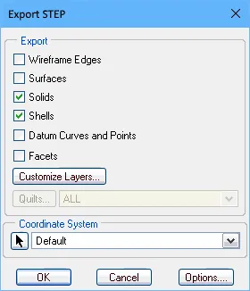
追加された STEP エクスポート出力をダブルクリックするか、File » Export » STEP 3Dコマンドを起動することでアクセスできる Export Optionsダイアログは、生成されたファイルに含まれるボードオブジェクトを決定するオプションを含む、様々な選択を提供します。
 MCADアプリケーションで表示されるエクスポートされたSTEPファイル。上のイメージファイルにはパッドホールや3Dボディが含まれず、下のイメージファイルにはすべてのオブジェクトが含まれる。
エクスポートオプションダイアログのオプションとコントロール
.
エクスポートオプションダイアログは、STEP、PARASOLID、またはVRML形式のファイルにエクスポートするときに開きます。このダイアログの内容は、フォーマットや、File » Exportコマンドを使用してエクスポートするか、Output Jobファイルの一部として設定されたOutputterを使用してエクスポートするかによって若干異なります。以下にバリエーションを示します。
ボードオプション
Layer Stack Regionsモードで設定した時、PCBパネルのFold Stateスライダで定義した折り目量は、Export Optionsダイアログが開いた時、デフォルトの折り目量になることに注意してください。
-
スキップフリー3Dボディ- フリー3Dモデルなしでエクスポートできるようにします。
-
Hidden 3D Bodiesをスキップ- 隠された3Dモデルなしでエクスポートできるようにします。
-
Export As Single Part- このオプションはSTEPファイルにエクスポートする場合にのみ適用されます。STEPファイルを単一パーツとしてエクスポートするか、コンポーネントごとに1つのモデルとしてエクスポートするかをチェックします。このオプションを有効にすると、STEPファイルはパーツとして保存され、アセンブリとしては保存されません。
3Dボディを持つコンポーネント
これらのオプションは、File » Exportコマンドでダイアログにアクセスした場合のみ利用可能です。
エクスポートされたファイルに含めるコンポーネントのオプションを選択します。オプションは、エクスポートプロセスを高速化し、ファイルサイズを小さくするために、完全な詳細と限定された詳細のいずれかを選択できるように設計されています。
-
Export All - すべてのコンポーネントをエクスポートします。このオプションは処理速度が遅く、エクスポートされるファイルのサイズが大きくなります。
-
Export Selected - 選択したコンポーネントのみをエクスポートします。このオプションの方が高速で、エクスポートされるファイルのサイズが小さくなります。
ボードのカットアウトは常にエクスポートに含まれます。
エクスポートする特定のコンポーネントや穴を選択するのは、2D の方が簡単です。ボードのみをエクスポートしたい場合は、Export Selectedを選択し、ドキュメント内の何も選択しないでください。PCBにマウントされていない、フリーフローティングの3Dボディもエクスポートに含まれます。これらを含めないようにするには、フリーフローティング3Dボディを選択せずにExport Selected オプションを使用します。
3Dボディエクスポートオプション
以下のオプションは、押し出し(単純)3DボディとSTEPモデル3Dボディの両方が割り当てられているコンポーネントに適用されます。
-
Prefer simple bodies - コンポーネントの押し出し(単純)3Dボディバージョンをエクスポートする場合に選択します。
-
Prefer generic 3D models - 一般的な3Dボディバージョンをエクスポートする場合に選択します。
-
Export both - 押し出し3Dボディとジェネリック3Dボディの両方のバージョンをエクスポートする場合に選択します。
押し出された3Dボディだけがコンポーネントとして利用できる場合、それらは常にエクスポートされます。
銅のエクスポートオプション
これらのオプションは、PARASOLID形式でエクスポートする場合にのみ利用可能です。
以下のオプションを使用して、銅のエクスポートのオプションを選択してください。
-
Export Without Copper - 銅なしで輸出する。
-
Export Copper Only- 銅のみを輸出する場合に選択します。
-
Export Selected Only - 選択されたオブジェクトに属する銅オブジェクトをエクスポートします。
-
Export By Layer- 銅をレイヤー別にエクスポートします。ドロップダウンを使って、以下のレイヤーのいずれかを選択します:
-
Top Layer
-
Mid-Layer 1
-
Mid-Layer 2
-
Bottom Layer
このモードは、選択したレイヤー上の銅オブジェクト(そのレイヤー上のスルーホールパッドとビアリングを含む)のみをエクスポートする必要がある場合に選択します。
Export Copper Only、Export Selected Only、またはExport By Layer オプションを有効にすると、銅以外のエクスポートオプションが選択されているにもかかわらず、銅のオブジェクトだけがエクスポートされます。Export Without Copper またはExport All の場合、選択した他のコンポーネントオプションによって、ボードとコンポーネントが表示されます。
パッド穴
以下のオプションは、File " Export コマンドでダイアログにアクセスした場合のみ利用可能です。
以下のオプションを使用して、エクスポートされたファイルにどの穴を含めるかを選択します。このオプションは、エクスポートプロセスを高速化し、ファイルサイズを小さくするために、完全な詳細か限定的な詳細かを選択できるように設計されています。
-
Export All- ボード内のすべての穴をエクスポートするために選択します。このオプションは遅く、エクスポートされるファイルのサイズが大きくなります。
-
Export Selected- 選択された穴のみをエクスポートするために選択します。このオプションはより速く、エクスポートされたファイルのサイズを小さくします。
以下のオプションは、ダイアログがOutJobファイルを通してアクセスされた場合にのみ利用可能です。
-
Export Mechanical Component Pad Holes- このボックスをチェックすると、メカニカルコンポーネントのパッド穴がエクスポートされます。
-
Export Electrical Component Pad Holes- このボックスをチェックすると、電気コンポーネントのパッドホールがエクスポートされます。
-
Export Free Pad Holes - このボックスをチェックすると、フリーパッドホールがエクスポートされます。
コンポーネントサフィックス
以下のオプションを使用して、エクスポートされるコンポーネントのサフィックスを指定します。
-
None - コンポーネントにサフィックスは適用されない。
-
Board file name- コンポーネントのサフィックスとして一般的な3Dファイル名を使用します。
-
Custom - コンポーネントのサフィックスをカスタマイズする場合に選択します。テキストボックスにカスタムサフィックスを入力します。
エクスポートしたファイルに関する注意事項
-
Export OptionsダイアログでExport Selectedオプション (3D Bodies と Pad Holes) が有効になっているが、PCB エディタでオブジェクトが選択されていない場合、生成された STEP ファイルは、これらのオブジェクトタイプを含みません。
-
ボードは常にエクスポートされます。全てのコンポーネントを除外(ボードのみエクスポート)するには、コンポーネントを選択していない状態でExport Selectedオプションを有効にします。
-
選択したコンポーネントだけをエクスポートしたい場合、一般的に2D表示モードで選択する方が簡単です。
-
Export as Single Partオプションを選択すると、生成されたSTEPモデルはコンポーネントモデルのアセンブリではなく、単一パーツとして保存されます。これにより、エクスポートされたSTEPモデルは簡素化されますが、受信側のMCADアプリケーションで個々のコンポーネントを選択することができなくなります。
-
Export 3D機能で生成された STEP ファイルは、ソース PCB デザイン内の原点に対してモデルグラフィックを配置します。インポートされたモデルが表示されない場合、現在のズームレベルで画面外にある可能性があります。
-
Free 3D Bodiesは、エンクロージャのような PCB エディタに配置された追加の 3D モデルです。
-
3D Bodies Export Optionsは、PCB ライブラリエディタでコンポーネントのフットプリントに追加された 3D ボディ/モデルに適用されます。シンプルボディという用語は、押し出し、円筒、または球体の 3D Body オブジェクトを指します。
-
STEPファイルでは、各コンポーネントはその識別子によって識別されます。MCADデザイナーが複数のボードを単一のMCADファイルにインポートする必要がある場合、識別子の衝突が発生する可能性があります。これを避けるために、Component Suffixを含めてください。
-
Export Folded Boardオプションは、デザインに折り曲げ線が定義されている場合にのみ機能します。ボードを部分的に折りたたんでエクスポートするには、Export コマンドを実行する前に、PCBパネルのLayer Stack RegionモードでFold Stateスライダを使用して折りたたみ量を設定します。定義された値は、自動的にExport Optionsダイアログで適用されます。

PCB エディタからエクスポートし、Rhinoceros 3D MCAD デザインソフトウェアにインポートした部分的に折りたたまれたリジッドフレックスボード。
-
メカニカル図面/ビューイングソフトウェアを使用できない場合は、エクスポートした STEP ファイルを Altium Designer で配置した3D Body オブジェクトにインポートして確認できます。
Altium DesignerMulti-board Assemblyドキュメントは、STEP ファイルフォーマットにエクスポートできます。Outputjob ファイルの[Add New Export Output]メニューのMBA Export STEPエントリを使用するか、Altium Designer の Multi-board Assembly エディタのメインメニューからFile » Export » STEP 3Dコマンドを選択します。
IPC Component Wizard からの保存
PCB Library エディタで IPC 準拠のフットプリントを作成する自動IPC 準拠フットプリントウィザードは、3D STEP ファイルとして生成されたフットプリントモデルを保存(プレビュー)する追加オプションを提供します。STEP ベースのモデルは、生成された IPC 準拠フットプリントに埋め込むことができ、また、*.stepファイルとして指定の場所に保存することもできます。
IPC Component Wizardは PCB フットプリントエディタ(Tools » IPC Compliant Footprint Wizard)から起動し、ウィザードの最後のFootprint Destinationページで STEP エクスポートオプションを有効にします。生成された STEP ファイルモデルは、ウィザードで入力されたコンポーネント寸法と正確に一致します。
 コンポーネントのSTEPモデルを生成して埋め込むオプションとともに、ウィザードではこれをSTEP 3Dモデルファイルとして保存することもできます。
STEP ファイルのインポート
PCB または PCB フットプリントへのインポート
STEP ファイルは、2つの異なるアプローチで Altium Designer にインポートして使用できます。使用するアプローチは、基本的に STEP ファイルがどのようにデザインに適用されるかに依存します:
-
MCAD アプリケーションで生成された筐体のような最終製品設計の機械的要素を表す STEP ファイルは、一般的に PCB レイアウトにインポートされます。
-
3Dコンポーネントボディを表すSTEPファイル(インターネットからダウンロードまたはローカルで作成)は、一般的にPCBフットプリントにインポートされます。
Altium Designer の PCB と PCB フットプリントの両方のドメイン内で、STEP ファイルは必要に応じて配置、整列される専用の3D Body オブジェクトにインポートされます。詳しくは、3D Body Object Placementを参照してください。
MCADからAltium Designerで使用するためにエンクロージャとボード形状をエクスポートする
一般的なアプローチでは、機械設計者が3Dボディオブジェクトをインポートします。
一般的なアプローチは、機械設計者が最初のコンセプトモデルを作成し、関係者全員が製品の外観を把握できるようにすることです。そこから機械設計者が筐体設計を洗練させ、初期ボード形状を定義します。
そのエンクロージャとボード形状は、STEPフォーマットでMCADツールから保存し、PCBエディタのデザインスペースに配置することで、ECAD設計者に引き継ぐことができます。Altium Designer には、MCAD ボード形状から直接 ECAD ボード形状を再定義するコマンドがあります。
STEP は複雑で非常に詳細なファイルフォーマットです。設計データの転送を最大限に成功させるために、以下の点に留意してください:
-
ボード形状は、別個のサブアセンブリである限り、エンクロージャ内にエクスポートできます。これが行われた場合、PCB エディタで数回クリックするだけで、メカニカル定義から ECAD ボード形状を再定義できます。
-
可能な限り AP214 フォーマットを使用してください。
-
サーフェスまたはソリッドのジオメトリーオプションがある場合は、それを使用する。
とPTC Creo(旧Pro/E)(2枚目の画像)に適したエクスポートオプション。")
SolidWorks(1枚目の画像)とPTC Creo(旧Pro/E)(2枚目の画像)に適したエクスポートオプション。
をクリックし、
Export PARASOLIDメニューのエントリを選択します。エクスポート出力は、ファイルから直接、または
Project Releaseプロセスの一部として生成できます。

または、Altium Designer の PCB エディタのメインメニューからFile » Export » PARASOLIDコマンドを選択します。
パネル化されたPCB(Embedded Board Array) を Parasolid フォーマットにエクスポートする場合、Route Tool Path はエクスポートされたファイルの全てのボードレイヤーを通してカットされ、ソースボードからのキャビティやボードカットはパネル化された PCB 上で考慮されます。
Parasolid ファイルのインポート
Altium Designer の PCB と PCB footprint ドメインの両方で、Parasolid ファイルは、必要に応じて配置、整列される専用の3D Body オブジェクトにインポートされます。詳細は3D Body Object Placementを参照してください。
SolidWorks パートファイルのインポートサポート
Altium Designer の PCB と PCB footprint ドメインの両方で、SolidWorks Part ファイル(*.sldprt)は、必要に応じて配置される専用の3D Body オブジェクトにインポートされます。詳しくは、3D Body Object Placementを参照してください。
SOLIDWORKSのバージョン2022または2023で作成されたSOLIDWORKS Parts File(*.SldPrt)フォーマットの3Dモデルは、3D Bodyオブジェクトで汎用3Dモデルを使用している場合にインポートできます。
VRML ファイルのエクスポートサポート
Altium Designer PCB ドキュメントは、VRML ファイルフォーマットにエクスポートできます。Outputjob ファイルで[Add New Export Output]をクリックし、Export VRMLメニューのエントリを選択します。エクスポート出力は、ファイルから直接、またはProject Releaseプロセスの一部として生成できます。

または、Altium Designer の PCB エディタのメインメニューからFile » Export » VRMLコマンドを選択します。
IDF ファイルのインポート/エクスポートサポート
-
Altium Designer はバージョン 3.0 までの IDF フォーマットのデータをサポートしています。
-
IDF ファイルのインポート/エクスポート機能は、IDFインポーター/エクスポート - ![]() show image から利用できます。
show image から利用できます。
インストールされたコア機能の変更については、Altium Designer のインストールと管理のページを参照してください。
IDF ファイルのエクスポート
Altium Designer PCB ドキュメントは、IDF ファイルフォーマットにエクスポートできます。Outputjob ファイルで、[Add New Export Output]をクリックし、Export IDFメニューのエントリを選択します。エクスポート出力は、ファイルから直接、またはProject Releaseプロセスの一部として生成できます。

または、Altium Designer の PCB エディタのメインメニューからFile » Export » IDF Boardコマンドを選択します。
File Export IDFダイアログは、エクスポートされた IDF ファイルのプロパティを設定するコントロールを提供します。ダイアログは、Outputjob ファイルで追加された IDF エクスポート出力をダブルクリックするか、File » Export » IDF Boardを選択した後にExport FileダイアログでSaveをクリックすることでアクセスできます。

File Export IDFダイアログ
File Export IDFダイアログのオプションとコントロール
<Enter Schematic Parameter>には、コンポーネント名のベースとなる回路図パラメータを括弧内に入力します。
-
Component Outlines From Multiple Component Bodies
-
Generated Files- IDF ファイルをエクスポートすると、2つのファイルが生成されます。1つは PCB の物理的なサイズや形状、コンポーネントの位置に関する情報を含み、もう1つは名前、サイズ、形状を含む各コンポーネントに関する情報を含みます。これらは通常、それぞれボードファイルとライブラリファイルと呼ばれます。CAD パッケージによって、ボードファイルとライブラリファイルの拡張子は異なります。ドロップダウンを使用して、生成されたファイルのボードファイルとライブラリファイルの拡張子を選択します。選択肢には以下が含まれます:
-
.brdと.pro
-
.brdと .lib
-
.emnと .emp
-
.bdfと .ldf
-
.idbと .idl
-
.idfと .lib
-
Use Unicode- このボックスをチェックすると、生成されるファイルのテキストにUnicode標準が使用されます。
IDF ファイルのインポート
アクティブな PCB ドキュメントに IDF ファイルをインポートするには、Altium Designer の PCB エディタのメインメニューからFile » Import » IDF Boardコマンドを選択します。コマンドを選択すると、インポートした IDF ファイルのプロパティを設定するFile Import IDFダイアログが開きます。

File Import IDFダイアログ
File Import IDFダイアログのオプションとコントロール
-
Offsets-XとYのオフセット距離をテキストボックスに入力します。
-
Board File Import Options- インポートしたい項目のチェックボックスを有効にします。
-
OK- クリックしてインポートプロセスを開始します。
IDXファイルのインポート/エクスポートサポート
より多くのエレクトロニクス製品が電気的および機械的コンポーネントの両方を含むようになり、製品のリリースサイクルが短くなるにつれて、ECADとMCADドメイン間のコラボレーションを強化する必要性が高まっています。しかし、そのコラボレーションは必ずしもスムーズではありません。電気設計者と機械設計者は、しばしば電子メールをやり取りしたり、互いの設計ツールに手を出したりしなければなりません。その解決策のひとつが、信頼できる作業環境を離れることなく、アイデアや変更の提案をグラフィカルに伝えることができるコラボレーションの方法を使うことだ。このような方法は、XMLベースの交換ファイルフォーマットであるIDX(Incremental Design EXchangeフォーマット)を通じて提供される。
この中間交換ファイル(*.idx)により、電気設計者は、機械設計者が必要とする(価値のある)基板設計への変更のみをエクスポートすることができます。逆に、機械設計者は変更案を電気設計者に戻すことができ、電気設計者はそれらの変更を設計にインポートすることができます。
ECADとMCADドメイン間のこの標準的なコラボレーションは、Altium DesignerのMCAD IDX Exchangeエクステンションでサポートされています。この拡張機能により、IDX交換フォーマットを使用して、Altium Designerと機械CADアプリケーション(SOLIDWORKSなど)間でデータをインクリメンタルに交換することができます。機能には、Cu 形状の転送だけでなく、変更要求のサポートが含まれます。
-
Altium Designer は IDX フォーマットバージョン 2.0 のみをサポートしています。
-
IDX ファイル交換機能は、MCAD IDX Exchangeソフトウェアエクステンション - ![]() show image から利用できます。
show image から利用できます。
エクステンションの詳細については、こちらをご覧ください。
コラボレーションのためのベースラインファイルの開始
コラボレーションは、電気設計者が最初のIDXファイルを作成する場合と、機械設計者が行う場合のどちらからでも開始できます。電気設計者が作成する場合、作成されたファイルはECAD Baselineファイル(ECAD Baseline.idx)と呼ばれ、その後機械設計者が使用できるようになります。機械設計者が行う場合、それはMCAD Baselineファイル(MCAD Baseline.idx)と呼ばれ、その後電気設計者が利用できるようになります。
Altium Designerからのエクスポート(ベースラインのECAD作成)
PCB エディタがアクティブな時に Altium Designer の右下にある ボタンをクリックし、メニューからMCAD IDX Exchangeエントリを選択します。
パネルは、メインTools メニューからMCAD IDX Exchangeコマンドを使用してアクセスすることもできます。
コラボレーションを開始するには、Export Baselineボタンをクリックします。Export EDMD Baselineダイアログが表示され、カッパーオブジェクトのエクスポートなどのオプションが提供されます。
銅をエクスポートすると、IDX ファイルのサイズが大きくなり、MCAD 側の処理に時間がかかります。さらに、IDXテクノロジーは銅オブジェクトの変更検出をサポートしていません。
 ECAD Baselineを作成してAltium Designerからコラボレーションを開始します。
Altium Designerへのインポート(ベースラインのMCAD作成)
ベースラインファイルが MCAD 側で作成されている場合、File » Import » MCAD IDX Baselineコマンドを使用して Altium Designer にインポートできます。Import MCAD Baselineダイアログが開きます。これを使用して、MCAD ベースラインファイル(MCAD Baseline.idx)、および提案された変更を同期する PCB ドキュメントをブラウズして指定します。
 MCAD Baseline をインポートすることで、Altium Designer 内からコラボレーションを受け付けます。
-
Input MCAD Baseline File-
 をクリックして、インポートする IDX ファイルを参照、選択します。
-
Output PCB File- をクリックして、提案された変更が同期される希望の PCB ファイルをブラウズして選択します。
MCAD ベースライン IDX ファイルがインポートされると、コラボレーションはMCAD IDX Exchange パネルを通して進みます。
コラボレーションフォルダ
Altium Designer からコラボレーションを開始する(IDX Baseline ファイルを作成する)場合、コラボレーションフォルダはオリジナルのボード設計プロジェクトの下に作成されます。フォルダは、.PcbDoc_EDMD の形式で PCB ドキュメント名を使用して命名されます。フォルダには 2 つのファイルが含まれます:
-
AD_EDMD_State.xml
-
ECADベースライン.idx
Show In Explorerコントロール(最初のエクスポート後にのみ利用可能)をクリックするか、 ボタンをクリックして関連メニューからOpen Collaboration Folderエントリを選択することで、MCAD IDX Exchangeパネルから生成されたフォルダにすばやくアクセスできます。

フォルダとベースライン ファイルの作成。
変更の同期
MCAD IDX Exchangeパネルは、ECADとMCADドメイン間で変更を同期させるためのコントロールを提供します。変更は IDX Changes ファイルを通して提案されます:
-
メカニカル設計者が変更を提案し、新しい IDX Changes ファイルで送信した場合、パネルはそれらの変更を検討するために PCB デザインに受信(インポート)できます。
-
ボードに変更が加えられた場合、パネルはこれらの変更(銅の変更を除く)を検出し、機械設計者が利用できる IDX Changes ファイルにエクスポートできるようにリストアップします。
ボード変更の検出とエクスポート
コンポーネントを削除するなど PCB ドキュメントに変更を加える場合、その変更はMCAD IDX Exchangeパネルの上部にある ボタンをクリックすることで検出できます。検出された変更は、パネルのBoard Changes領域に一覧表示されます:
-
Object- 例えば、コンポーネントのデジグネータ。
-
Change - 例えば、デザインから削除されたコンポーネントにはRemoved、追加されたコンポーネントにはAddedを指定します。
-
Status - この変更はECAD側で行われるため、Proposedとなります。
-
Proposition Comment- 機械設計者に変更を説明するためのメモ。必要に応じて入力する。
 ボードの変更を検出する。
すべての変更が行われ、検出され、提案コメントが追加されると、それらの変更は ボタンを使用してエクスポートできます。これによりIDX Changesファイル(ECAD Changes n.idx)が作成されます。

ボードへの変更案が作成されたら、機械設計者に変更案を送るためにIDX Changesファイルを作成するためにエクスポートします。
変更案をインポートして表示するのは機械設計者側です。その後、各変更案を順番に受け入れるか拒否し、IDX Responseファイル(MCAD Response n.idx)で返答を送り返します。これを受信したら、 ボタンを使用してレスポンスをインポートする。レスポンスファイルの変更を適用するには、
 ボタンをクリックします。これにより、ECAD側から機械設計者にIDXレスポンスファイル(ECAD Response n.idx)が返送されます。
この "ハンドシェーキング "は、両者が行われた変更と同期していることを保証します。
提案された変更を放棄するには、

ボタンをクリックします。
Board Changesリストはクリアされます。
変更のインポート
機械設計者が変更を提案する場合、それらの変更はIDX変更ファイル(MCAD Changes n.idx)で提案されます。パネルの ボタンを使用して変更をインポートします。変更は、パネルのChanges from Mechanical CADに一覧表示されます:
-
Object- 例えば、コンポーネント指定子。
-
Change - 例えば、デザイン内で移動されたコンポーネントのMoved。
-
Status - MCAD 側の変更なので、Proposedになります。
-
Proposition Comment- 電気設計者に変更を説明するためのメモ。
 機械設計者が提案した変更をパネルにインポートする。
電気設計者として、提案された各変更を順番に表示し、受け入れるか拒否するかはあなた次第です。提案された変更を受け入れるには、関連するAccept チェックボックスをチェックします。拒否する場合は、チェックを外したままにします。また、それぞれのResponse Commentフィールドに返答を入力することができます。
すべての変更案の受諾/拒否が完了したら、 ボタンをクリックします。受け入れられた変更は PCB ドキュメントに適用され、IDX レスポンスファイル(ECAD Response n.idx)が作成され、メカ設計者に送り返す準備ができます。
コラボレーションのリセット
プロジェクトのコラボレーションを完全にリセットするには、 ボタンをクリックし、関連するメニューからReset Collaborationエントリを選択します。パネル内の現在のエントリはすべてクリアされ、コラボレーションフォルダ内のファイルはすべて削除されます。これで振り出しに戻り、ベースラインファイルをエクスポート、またはインポートし、新たにコラボレーションを開始することができます。
リセット前にデザインに適用された変更は残ります。

 AI で翻訳