新しいルームは、PCB Rule and Constraints Editor または Constraint Manager で新しい制約を定義することでも作成できます。
設計制約の定義にどのアプローチを使用していますか?
Altium Designer は、設計制約を定義するための 2 つの異なるアプローチをサポートしています。Constraint Manager と PCB Rule and Constraints Editor です。
PCB Rule and Constraints Editor は、PCB editor で制約を定義するために最初に開発されたインターフェースです。PCB Rule and Constraints Editor を使用する場合、設計者は what objects the constraint (rule) applies to と how those objects are to be constrained を定義します。このアプローチは、制約を適用したいオブジェクトを正確にターゲットできる点で強力です。すべて(たとえば全ネット)に適用することも、基板上の特定オブジェクト(そのパッド)にまで絞り込むこともできます。この柔軟なターゲティングは、クエリ言語 によって駆動されるルールエンジンで実現されています。
Constraint Manager は、制約定義の作業にオブジェクト中心の視点をもたらします。設計者はオブジェクトの観点から作業し、設計に必要な各種の電気的/物理的制約を、スプレッドシートのようなインターフェースで適用します。Constraint Manager でオブジェクトを選択すると、グラフィカルエディタ側でも該当オブジェクトがハイライト表示されます。これにより、たとえば「このネットクラスはこの線幅で配線し、このクリアランスで、このビアを使い、このポリゴン接続スタイルにする」といった、オブジェクトに対する要件を容易に設定・確認できます。さらに、そのネットクラスに対して「これらのレイヤで配線する」「これらのインピーダンスにする」といった要件を指定することもできます。このオブジェクト中心のビューは PCB Rule and Constraints Editor では実現できません。 最終的にソフトウェアは、オブジェクト中心の制約を PCB Rule and Constraints Editor で定義されるのと同じルール形式に変換します。PCB editor から制約を開いて表示する場合は、All Rules ビューに切り替えてください。
Constraint Manager は、プロジェクト作成時に Create Project ダイアログ で Constraint Management オプションを有効にした場合にのみ、PCB設計プロジェクトで利用できます(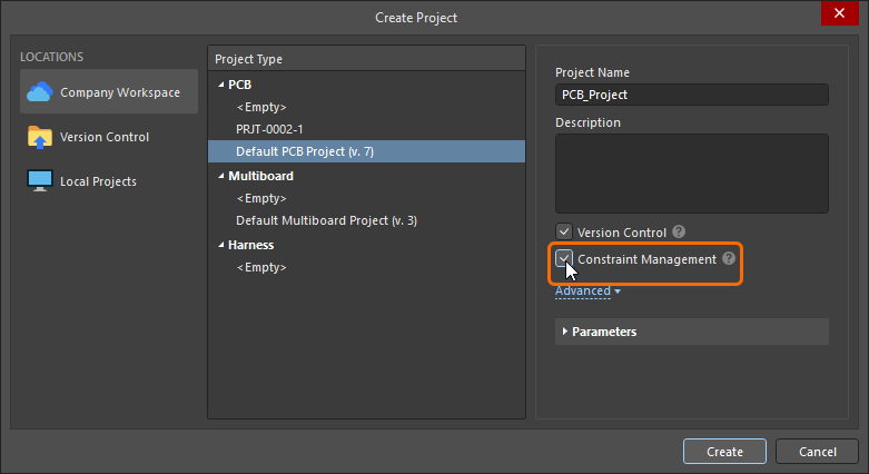 )。有効にしていない場合は、代わりに PCB Rule and Constraints Editor を使用する必要があります。現在のPCBプロジェクトでどちらの設計制約管理方式が使われているかを素早く確認するには、プロジェクトのPCBドキュメントを開き、Design メニューをクリックして、利用可能なコマンドを確認します。Constraint Manager – このプロジェクトでは Constraint Manager が使用されている、または Rules – このプロジェクトでは PCB Rule and Constraints Editor ダイアログが使用されています。
このドキュメントページでは、 PCB Rule and Constraints Editor ダイアログと Constraint Manager の両方で定義された制約の画像を示します。なお、constraint と rule という用語は同義として使われています。
新しいルーム定義(Room Definition)設計制約の追加
PCB Rules and Constraints Editorの場合
配置または作成された各ルームについて、関連する Room Definition 設計制約が自動的に作成されます。逆も同様で、この種類の新しいルールを追加すると、対応するルームオブジェクトが設計空間に表示されます。また、反対方向も成り立ちます。グラフィカルエディタでルームを削除すると制約は自動的に削除され、設計制約を削除するとグラフィカルオブジェクトが削除されます。
ルーム制約を PCB Rules and Constraint Editor から定義する場合、デフォルトで 5インチ×5インチのルームオブジェクトが作成され、Absolute Origin(編集空間の左下)から 1インチの位置に配置されます。なお、原点マーカーが表示するのはユーザー定義の Relative Origin で、編集空間内の任意の場所に設定できます。
 新しいルーム制約を追加すると、編集空間にデフォルトのルームが定義されます。
制約を追加した後、編集空間に戻って ルームをグラフィカルに編集 できます。あるいは、PCB Rules and Constraints Editor 内でルーム制約を編集し、Define ボタンをクリックして形状を対話的に定義することもできます。 ルームは基板上の領域を定義するため、対話的にルームを配置して設計制約を自動作成させる方法のほうが一般的です。
PCB Rules and Constraints Editor で新しい制約を追加する方法について詳しく学ぶ。
Constraint Managerの場合
Constraint Manager: で新しいコンファインメント(ルーム)制約を作成するには、All Rules ビューに切り替え、Placement カテゴリで Room Definition を選択し、Advanced Rules リスト内を右クリックして、コンテキストメニューから Add Advanced Rule を選択します(下図参照)。
 Constraint Managerで新しいルーム制約を追加できます。
この段階ではグラフィカル編集空間にルームオブジェクトは存在しません。Define ボタンをクリックして(PCBエディタに切り替わります)、ルームの形状を定義する必要があります。これが完了すると、ルーム制約とルームオブジェクトの両方が存在する状態になり、制約を保存できます。
-
ルーム制約を、基板上のその領域の内側(または外側)にオブジェクトを拘束する目的で使用する場合、次のステップは Constraint Manager 下部にある Object Match およびその他の制約設定を構成することです。詳細は続けてお読みください。
-
ルーム制約を、配線幅など別タイプの制約における領域定義として使用する場合は、Defining Constraints Within a Room セクションを参照してください。
Constraints Manager で新しい制約を追加する方法について詳しく学ぶ。
ルーム制約とは?
前述のとおり、ルームはPCBのいずれかの表層レイヤ上に定義された領域で、その基板領域内の設計要件を定義するために使用されます。
すべての設計制約には、次の2つの重要な要素があります。
ルーム制約が、部品のない基板領域で定義されている場合、Object Match 条件(the objects this constraint applies to)はデフォルトで False となり、この制約はどのオブジェクトにも適用されないことを意味します。必要に応じて編集してください。
 新規作成されたルーム定義。ルールスコープが False で、どのオブジェクトにも適用されない点に注意してください。
部品クラスを拘束する
ルーム制約の一般的な使い方は、部品クラスの配置場所を定義し、その部品クラスを基板上の特定領域に固定することです。
 Encoder 部品クラスは、基板の Top Layer 上にある Room-Encoder というルーム内に拘束されています。
上の画像は、PCB Rules and Constraints Editor(基本的には Constraint Manager 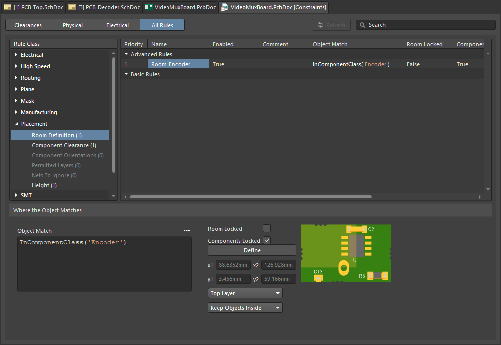 と同じ)において、
Encoder 部品クラスが基板の Top side 上の Room-Encoder ルーム within に拘束されている様子を示しています。 部品がルームに割り当てられると、ルームを移動した際に部品も一緒に移動します。部品を動かさずにルームだけを移動したい場合は、関連する Room Definition ルールを一時的に無効化してください。
Room Definition 設計制約 について詳しく学ぶ。
PCBエディタにはルームを扱うための強力なツールが多数用意されています。詳しくは本ページの Working with Rooms セクションを参照してください。
ルームは、それ自体が設計制約(Room Definition)であるだけでなく、Width、Clearance、Via Style など、別の設計制約のスコープを基板上の特定領域に絞り込むためのオブジェクトとしても使用できます。このトピックは本ページの Defining Constraints Within a Room セクションで説明しています。
ルームは、回路の繰り返しセクションを含む設計(Altium Designer ではマルチチャネル設計と呼ばれます)でも使用できます。マルチチャネル設計では、エンジニアは繰り返しチャネルの回路図を1回だけ作成し、そのチャネルが何回繰り返されるかの情報を追加します。設計を回路図からPCBへ転送すると、ソフトウェアがその繰り返し回路を必要回数分自動的にスタンプし、各チャネルをそれぞれの設計ルーム内に配置します。 PCB設計者がそのうち1つのチャネルをルーム内で配置・配線した後、ソフトウェアに指示して、その配置と配線を他のすべてのチャネルへ複製できます。
multi-channel design について詳しく学ぶ。

 AI で翻訳