Новую комнату также можно создать, определив новое ограничение в PCB Rule and Constraints Editor или в Constraint Manager.
Какой подход используется для задания проектных ограничений?
Altium Designer поддерживает два различных подхода к заданию проектных ограничений: Constraint Manager и PCB Rule and Constraints Editor.
PCB Rule and Constraints Editor — это первоначальный интерфейс, разработанный для задания ограничений в PCB editor. Если используется PCB Rule and Constraints Editor, проектировщик задаёт: what objects the constraint (rule) applies to и how those objects are to be constrained. Этот подход мощный, поскольку позволяет точно нацеливаться на объекты, которые нужно ограничить: правило может применяться ко всему (например, ко всем цепям), либо быть нацелено на конкретный объект на плате (например, на конкретную площадку). Такая гибкая адресация объектов проекта реализована с помощью механизма правил, управляемого языком запросов.
Constraint Manager привносит объектно-ориентированный подход к задаче определения ограничений. Проектировщик работает с точки зрения объектов, применяя необходимые электрические и физические ограничения для проекта в интерфейсе, похожем на электронную таблицу, при этом соответствующие объекты подсвечиваются в графическом редакторе по мере их выбора в Constraint Manager. Это позволяет легко настраивать и проверять все требования к объекту, например: этот класс цепей должен трассироваться с такой шириной, с таким зазором, с использованием такого переходного отверстия и такого стиля подключения полигона. Также может потребоваться, чтобы этот класс цепей: трассировался на этих слоях, с такими импедансами. Такой объектно-ориентированный взгляд невозможен в PCB Rule and Constraints Editor. В конечном итоге программа преобразует объектно-ориентированные ограничения в тот же формат правил, который задаётся в PCB Rule and Constraints Editor; переключитесь в представление All Rules, когда ограничения открыты из PCB editor, чтобы просмотреть их.
Объект Constraint Manager доступен только в проекте проектирования печатной платы, если при создании проекта в диалоге Create Project dialog была включена опция Constraint Management (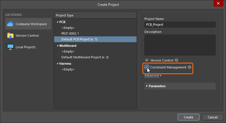 ). Если нет, то необходимо использовать PCB Rule and Constraints Editor . Чтобы быстро проверить, какой подход к управлению проектными ограничениями используется в текущем PCB‑проекте, откройте PCB‑документ проекта, щёлкните меню Design и проверьте, какая команда доступна: Constraint Manager – для этого проекта используется Constraint Manager , или Rules – для этого проекта используется диалог PCB Rule and Constraints Editor .
На этой странице документации показаны изображения ограничений так, как они определяются и в диалоге PCB Rule and Constraints Editor , и в Constraint Manager. Обратите внимание, что термины constraint и rule используются как взаимозаменяемые.
Добавление нового проектного ограничения определения комнаты
В PCB Rules and Constraints Editor
Для каждой размещённой или созданной комнаты автоматически создаётся связанное проектное ограничение Room Definition. Верно и обратное: если вы добавляете новое правило этого типа, соответствующий объект комнаты появится в рабочем пространстве. Также действует и противоположное: если вы удаляете комнату в графическом редакторе, ограничение удаляется автоматически; или, если вы удаляете проектное ограничение, то удаляется и графический объект.
Если ограничение комнаты задаётся из PCB Rules and Constraint Editor, то создаётся объект комнаты по умолчанию размером 5×5 дюймов, со смещением 1 дюйм от Absolute Origin (нижний левый угол области редактирования). Обратите внимание: маркер начала координат отображает заданный пользователем Relative Origin, который можно установить в любом месте области редактирования.
 При добавлении нового ограничения комнаты в области редактирования определяется комната по умолчанию.
После добавления ограничения вы можете вернуться в область редактирования и отредактировать комнату графически. Либо, находясь в PCB Rules and Constraints Editor , вы можете отредактировать ограничение комнаты, затем нажать кнопку Define, чтобы интерактивно задать форму. Поскольку комната определяет область на плате, чаще комнату размещают интерактивно, а проектное ограничение создаётся автоматически.
Подробнее о том, как добавить новое ограничение, см. в PCB Rules and Constraints Editor.
В Constraint Manager
Чтобы создать новое ограничение confinement (room) в Constraint Manager: , переключитесь в представление All Rules, выберите Room Definition в категории Placement, затем щёлкните правой кнопкой в списке Advanced Rules и выберите Add Advanced Rule в контекстном меню, как показано ниже.
 Новое ограничение комнаты можно добавить в Constraint Manager.
На этом этапе объект комнаты ещё не существует в графическом пространстве редактирования — теперь нужно нажать кнопку Define (переключившись в PCB‑редактор) и определить форму комнаты. После этого и ограничение комнаты, и объект комнаты будут существовать, и ограничения можно будет сохранить.
-
Если ограничение комнаты будет использоваться для ограничения объектов внутри (или вне) этой области платы, следующий шаг — настроить Object Match и другие параметры ограничения в нижней части Constraint Manager. Читайте далее, чтобы узнать больше.
-
Если ограничение комнаты будет использоваться как определение области в другом типе ограничения, например для ширины трассировки, обратитесь к разделу Defining Constraints Within a Room, чтобы узнать больше.
Подробнее о том, как добавить новое ограничение, см. в Constraints Manager.
Что такое ограничение комнаты?
Как было сказано ранее, комната — это определённая область на одном из поверхностных слоёв PCB, которая используется для задания проектных требований внутри этой области платы.
Все проектные ограничения имеют два ключевых элемента:
-
what objects this constraint applies to (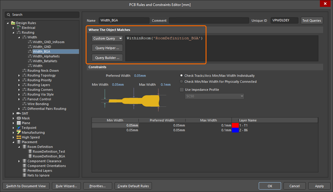 ), и,
), и,
-
how those objects are to be constrained ( ).
).
Если ограничение комнаты определено в области платы, где нет компонентов, критерий Object Match (the objects this constraint applies to) по умолчанию устанавливается в False, то есть это ограничение не применяется ни к каким объектам. Отредактируйте при необходимости.
 Вновь созданное определение комнаты. Обратите внимание, что область действия правила — False, то есть оно не применяется ни к каким объектам.
Ограничение класса компонентов
Распространённый способ использования ограничения комнаты — задать расположение класса компонентов, «зафиксировав» этот класс компонентов в определённой области платы.
.") Класс компонентов Encoder ограничен внутри комнаты с именем Room-Encoder на верхнем слое платы (Top Layer).
Класс компонентов Encoder ограничен внутри комнаты с именем Room-Encoder на верхнем слое платы (Top Layer).
На изображении выше показано, как класс компонентов Encoder ограничен within комнаты Room-Encoder на Top side платы в PCB Rules and Constraints Editor (по сути то же самое, что и в Constraint Manager 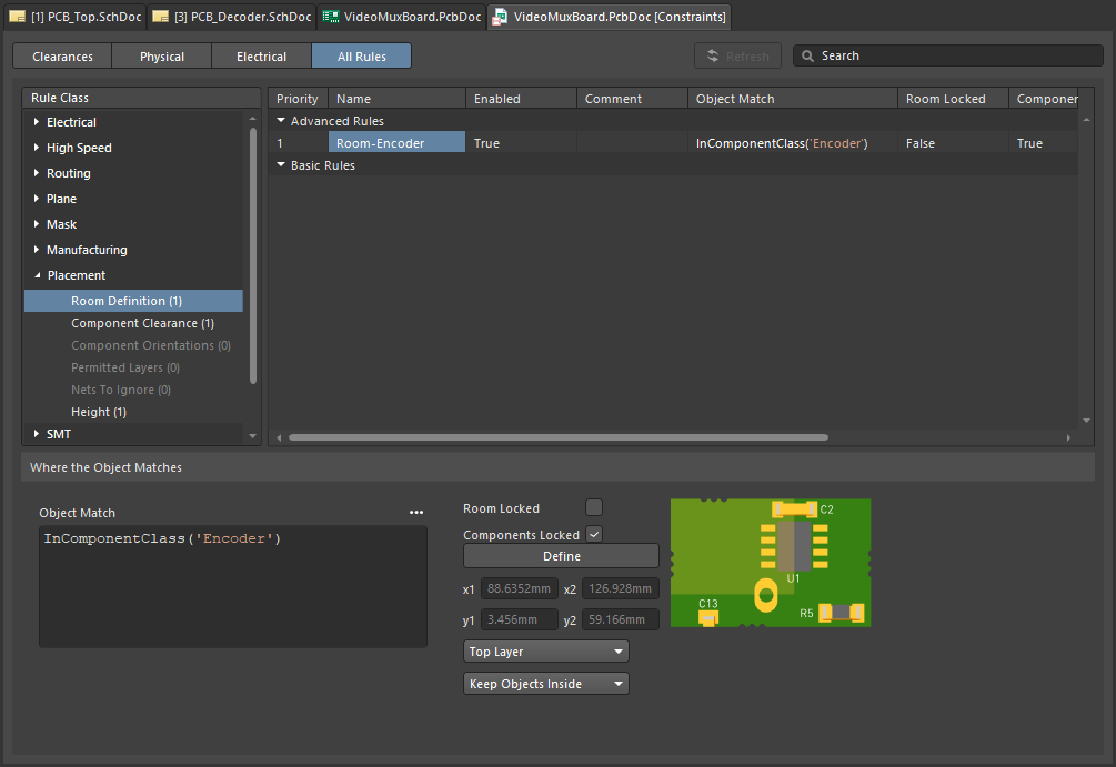 ). После назначения компонента(ов) комнате они перемещаются вместе с комнатой при её перемещении. Чтобы переместить комнату, не перемещая компоненты, временно отключите связанное правило Room Definition.
Подробнее о проектном ограничении Room Definition.
PCB‑редактор включает ряд мощных инструментов для работы с комнатами — подробнее см. в разделе Working with Rooms на этой странице.
Помимо того, что комната является самостоятельным проектным ограничением (Room Definition), её также можно использовать как объект, чтобы ограничить область действия другого проектного ограничения определённой областью платы, например Width, Clearance или Via Style. Эта тема рассматривается в разделе Defining Constraints Within a Room на этой странице.
Комнаты также можно использовать в проекте, который включает повторяющиеся участки схемотехники — в Altium Designer это называется многоканальным проектированием (multi-channel design). В многоканальном проекте инженер один раз создаёт схему повторяющегося канала и добавляет информацию о том, сколько раз этот канал повторяется. При переносе проекта со схемы на PCB программное обеспечение автоматически «штампует» эту повторяющуюся схемотехнику нужное количество раз, размещая каждый канал в своей проектной комнате. После того как PCB‑дизайнер разместит компоненты и выполнит трассировку одного из таких каналов в пределах его комнаты, он может затем указать программе повторить это размещение и трассировку для всех остальных каналов.
Подробнее о multi-channel design.

 Локализовано с помощью ИИ