ユニークな電子回路を作り出すのは、コンポーネントとそれらが互いにどのように接続されるかです。回路図では、コンポーネントのピンを互いに接続することで、設計の論理的表現を作成します。プリント基板を設計する際には、物理的なコンポーネントを配置し、配線で同じ接続性を作り出します。
物理的および論理的接続性
回路図上では、一つのコンポーネントから別のコンポーネントへワイヤーを引くことでその接続性を作り出すことができます。これは物理的接続性と呼ばれます。
また、ピンとピンを短いワイヤーとネットラベルを各コンポーネントのピンに配置することで接続することもできます。ソフトウェアはこれら二つのネットセクションを識別し、一つのネットとして接続します。このタイプの接続性は論理的接続性と呼ばれます。
物理的接続性を使用すると、ユーザーは回路を勉強する際に各ワイヤーを追跡できますが、多くのワイヤーは密集した回路図をもたらす可能性があります。一方、ネットラベルは配線の量を減らしますが、ユーザーはシートをスキャンしてすべての潜在的な接続を見つける必要があります。設計者として、設計に最も適した接続モデルを自由に決定できます。これには両方の技術の混合も含まれます。
物理的接続性を作り出すためにワイヤーを配置するか、論理的接続性を作り出すためにネットラベルを使用します。
回路図シート内で論理的接続性を作り出すだけでなく、回路図シート間で論理的接続性を作り出すためのオブジェクトもあります。この接続性の作成方法は、回路図をフラットデザインとして構造化するか、階層的デザインとして構造化するかによって異なります。以下で詳しく説明します。

シート間を接続するために使用できるさまざまなネット識別子があります。
接続の確認
Altium Designerの接続の確認機能(Design Insight機能の一部)は、プロジェクト内の接続関係を瞬時に表示します。オプショナルな回路図プレビューを含むドキュメントツリーとして表示され、選択可能な要素はプロジェクトの接続構造を通じて素早く視覚的にナビゲートする方法を提供します。
デフォルト設定状態では、接続の確認機能は以下を表示します:
-
回路図の接続オブジェクト(ワイヤー、ポートなど)上にカーソルを合わせると、関連するネット接続情報が表示されます。
-
オブジェクト上でAlt+ダブルクリックを使用すると、ツリーベースの接続性プレビューマップが表示されます。
この機能に加えて、信号ネットに属するオブジェクト上にカーソルを合わせてCtrl+Altを押すと、選択可能なツリービューが開きます。ツリー内で希望するシートをクリックすると、そのドキュメントに素早くジャンプできます。

この機能は、PreferencesダイアログのSystem - Design Insightページで、マウスホバーオプションをDocument Treeエントリーでチェックする/しないことで有効/無効にできます。

設計全体のネット接続性は、ワイヤーをクリックする際にAltキーを押し続ける(Alt+クリック)ことで、すべての回路図で強調表示することもできます。
回路内の選択した点に電気的に接続されたすべてのオブジェクトを選択するには、メインメニューからEdit » Select » Connectionコマンドを使用するか、Select ConnectionコマンドをActive Barで使用します。接続された電気オブジェクトを選択したいオブジェクトをクリックした後、その選択したオブジェクトに電気的に接続されているすべてのオブジェクトが選択され、シート上の他のすべてのオブジェクトを暗くするフィルタリングが適用されます。
接続性を作り出すために使用されるオブジェクト
回路図エディタには、接続性を作り出すために使用される以下のオブジェクトが含まれています。これらのオブジェクトは総称してネット識別子と呼ばれます。
| ネット識別子 |
機能 |
| バス |
ネットのセットをバンドルするために使用します (例: Data[0..7]。ネットには、特定の命名スキーム (Data0、Data1 など) を使用して順番に名前を付ける必要があります,...データ7)。この名前付けによって、バスの名前 (Data[0..7] など) が決まります。 |
| バスエントリ |
バスラインの反対側から2つの異なるネットをリッピングし、2つのネット間に短絡を生じさせないようにサポートするグラフィカルデバイスです。他の状況では必要ありません。 |
| オフシートコネクタ |
1 つの回路図シートから別のシート (同じシート内ではない) にネットを接続するために使用します。水平接続(フラットデザイン)のみをサポートします。OffSheet コネクタは、ポートと比較すると機能が制限されています。 |
| ネットラベル |
同じ回路図シート上の同じ名前の他のネットラベルへの接続を作成するために使用されるネット識別子。ネットには、ネットラベルによって自動的に名前が付けられます。ネットラベルは、コンポーネントのピン、ワイヤ、およびバスに配置できます。ネット ラベルは、プロジェクト オプションがNet Identifier Scopeを Globalで使用するように構成されていない限り、シート間で接続しないことに注意してください。 |
| ピン |
ピンは、回路図シンボル エディタに配置され、コンポーネント上の物理ピンを表します。ピンの一方の端のみが電気的にアクティブであり、ピンのホットエンドと呼ばれることもあります。 |
| ポート |
1つの回路図シートから別の回路図シートにネットを接続するために使用されます。接続性は、階層デザインでは垂直に、フラット デザインでは水平にすることができます (垂直デザインと水平デザインについては以下で説明します)。Project Optionsダイアログの Optionsタブで Allow Ports to Name Netsオプションが有効になっている場合は、ポート名を使用してネットに名前を付けます。この状況では、ポートは回路図シート内でも接続されますが、同じ名前のネットラベルには接続されません(詳細を学ぶ)。 |
| 電源ポート |
設計構造に関係なく、回路図プロジェクト全体で同じ名前の他のすべての電源ポートへの接続を作成します。ネットには、電源ポートによって自動的に名前が付けられます。このネットは、必要に応じて特定の回路図シートにローカライズできます(詳細を学ぶ)。 |
| シートエントリ |
シートシンボル内に配置され、そのシートシンボルの子シート上の同じ名前のポートへの接続を作成します。Project OptionsダイアログのOptionsタブでAllow Sheet Entries to Name Netsオプションが有効になっている場合、シート エントリはネット名として使用されます。 |
| 信号ハーネス |
ネット、バス、および低レベルの信号ハーネスの任意の組み合わせをバンドルするために使用されます。 |
| ワイヤ |
回路図上のポイント間に電気接続を形成するために使用されるポリライン電気設計プリミティブ。ワイヤは、物理ワイヤに似ています。 |
設定によって自動的に接続されるわけではない。これらのオプションは以下で議論される。
ネットラベル

ネットラベルは、回路図内の異なる点を識別し、電気的に接続する。
概要
回路図のコンポーネントピン間の電気的接続は、それらのピン間にワイヤを配置することによって作成できる。これはピンが物理的にワイヤで接続されているため、物理的接続と呼ばれる。接続は、ネットラベルなどの適切なネット識別子を使用することによって論理的にも作成できる。ネットラベルはネットに人間に優しい識別子を提供するだけでなく、実際にそれらを物理的に配線することなく回路上の点を接続することを可能にする。
使い方
ネットラベルは、以下の方法でのみ回路図エディタで配置が可能である:
-
メインメニューからPlace » Net Labelを選択。
-
デザインスペースの上部に位置するActive BarのグラフィックオブジェクトドロップダウンでNet Labelボタン( )をクリック。(Active Barボタンをクリックして保持すると、他の関連コマンドにアクセスできる。コマンドが使用されると、そのセクションのActive Barの最上位項目になる。)
-
デザインスペースで右クリックし、コンテキストメニューからPlace » Net Labelを選択。
-
Wiringツールバーのボタンをクリック。
配置
コマンドを起動すると、カーソルが十字線に変わり、カーソル上にネットラベルが浮かぶネットラベル配置モードに入ります:
-
Tabキーを押して、PropertiesパネルのNet Labelモードを開き、Net Nameフィールドを選択して編集の準備をします。新しいネット名を入力してください。
-
ネットラベルの左下の角が割り当てたいオブジェクトに触れるように位置を調整し、クリックするかEnterキーを押してネットラベルを配置します。
-
さらにネットラベルを配置するか、右クリックするかEscキーを押して配置モードを終了します。
ネットラベルがカーソルに浮かんでいて、ネットラベルの中心点が固定される前に、配置中に実行できる追加のアクションは以下の通りです:
-
Tab キーを押して配置を一時停止し、PropertiesパネルのNet Labelモードにアクセスして、その場でプロパティを変更できます。配置を再開するには、デザインスペースの一時停止ボタンオーバーレイ( )をクリックします。
-
XキーまたはYキーを押して、ネットラベルをX軸またはY軸に沿って反転させます。
-
Spacebarを押してネットラベルを反時計回りに、または Shift+Spacebarを押して時計回りに回転させます。回転は90°単位です。
配置中の考慮事項:
-
ネットラベルの電気的ホットスポットは左下の角であるため、この角が有効な接続を作るためにはワイヤー、バス、またはシグナルハーネスに触れる必要があります。
-
配置される前にネットラベルのNetプロパティが入力され、入力された値が数値で終わる場合、次のネットラベルはこの数値を自動的にインクリメントします。この振る舞いは、Auto-Increment During PlacementオプションをPreferencesダイアログのSchematic – Generalページで設定します。ネットラベルの場合、Primaryフィールドのみが適用されます。オブジェクトに複数のフィールドがある場合、Secondaryフィールドが適用されます。
グラフィカル編集
ネットラベルは、いわゆるインプレース編集を使用してグラフィカルに編集できます。インプレースでネットラベル文字列を編集するには、一度クリックして選択し、一時停止してからもう一度クリックして編集モードに入ります。
 |
文字列を選択するために一度クリックします。 |
 |
一時停止してから、もう一度クリックしてインプレース編集モードに入ります。 |
 |
文字列が選択され、置換える文字列を入力する準備ができました。 |
編集が完了したら、Enterキーを押すか、文字列からクリックして離れることでインプレース編集モードを終了します。
この機能は、Enable In-Place EditingオプションがPreferencesダイアログのSchematic – Generalページで有効になっている場合にのみ利用可能です。
注意
-
ネットラベルは単一の回路図シート内で論理的な接続を作成しますが、回路図シート間で接続を作成することはありません。これを行うには、ポートを使用する必要があります。
-
ネットラベルの上部にバーを含める(否定する)には、以下の方法のいずれかを使用します:
-
個々のネットがバスを形成する場合、それらがどのように命名されるかには特定の要件があります。詳細については、バスページを参照してください。
-
異なるタイプのネット識別子は、同じ名前を共有していても自動的には接続されません。例えば、AGNDと名付けられたネットラベルは、AGNDと名付けられた電源ポートに自動的に接続されません。それらを接続するにはワイヤーを配置する必要があります。
ネットラベルのプロパティ

位置
プロパティ
-
Net Name - ドロップダウンからネット名を選択するか、直接名前を入力します。
-
Font - 希望のフォント、フォントサイズ、色、太字、イタリック体などの属性を選択するためのコントロールを使用します。
-
Justification- 希望の配置に対応する矢印をクリックするか、中央に配置するための円をクリックして選択します。
オフシートコネクタ

オフシートコネクタは、回路図シート間の接続を作成するために使用されます。
概要
オフシートコネクタは、電気設計の基本要素です。オフシートコネクタは、同じ親シートシンボルから派生した複数の回路図シートを接続するために使用されます。
使い方
オフシートコネクタは、以下の方法でのみ回路図エディタで配置が可能です:
-
メインメニューからPlace » Off Sheet Connectorを選択します。
-
Active Bar上のOff Sheet Connectorコマンド( )を探して使用します。
-
デザイン空間で右クリックし、コンテキストメニューからPlace » Off Sheet Connectorを選択します。
配置
コマンドを起動すると、カーソルが十字に変わり、オフシートコネクタ配置モードに入り、カーソルにオフシートコネクタが浮かび上がります:
-
Tabキーを押して、プロパティパネルのOff Sheet Connectorモードを開き、Net Nameが選択され編集の準備ができます。新しいネット名を入力します。
-
接続したいワイヤにオフシートコネクタの電気的ホットスポット(カーソルで保持されている端)が触れるように位置を合わせ、クリックまたはEnterキーを押して配置を行います。
-
さらにオフシートコネクタを配置するか、右クリックまたはEscキーを押して配置モードを終了します。
配置中にオフシートコネクタがカーソルに浮かんでいる間に実行できる追加のアクションは:
-
Tab キーを押して配置を一時停止し、PropertiesパネルのOff Sheet Connectorモードにアクセスし、そのプロパティをその場で変更できます。ワークスペースの一時停止ボタンオーバーレイ()をクリックして配置を再開します。
-
XキーまたはYキーを押して、オフシートコネクタをX軸またはY軸に沿って反転させます。
-
Spacebar を押してオフシートコネクタを反時計回りに、または Shift+Spacebar を押して時計回りに回転させます。回転は90°の増分です。
配置される前にオフシートコネクタのネットプロパティが入力され、入力された値が数値で終わる場合、次に配置されるオフシートコネクタはこの数値を自動的にインクリメントします。この挙動は、PreferencesダイアログのSchematic – GeneralページのAuto-Increment During Placementオプションで設定されます。オフシートコネクタの場合、Primaryフィールドのみが適用されます。オブジェクトに複数のフィールドがある場合、例えばピンの場合はSecondaryフィールドが適用されます。
クロスリファレンス機能を使用すると、相互接続されたポート、シートエントリ、オフシートコネクタの位置を特定できます。クロスリファレンスをデザインに追加する方法について学びましょう。
グラフィカル編集
オフシートコネクタは、インプレース編集として知られる方法を使用してグラフィカルに編集できます。インプレースでオフシートコネクタ文字列を編集するには、一度クリックして選択し、一時停止してから、もう一度クリックして編集モードに入ります。
 文字列を選択するために一度クリックします。
 一時停止してから、もう一度クリックしてインプレース編集モードに入ります。
 文字列が選択され、置換え文字列を入力する準備ができました。
オフシートコネクタはインプレースで編集できます。
編集が完了したら、Enterキーを押すか、文字列からクリックして離れることでインプレース編集モードを終了します。
この機能は、
Preferencesダイアログの
Schematic – Generalページで
Enable In-Place Editingオプションが有効になっている場合にのみ利用可能です。
オフシートコネクタは独立したフォントプロパティを持たず、配置された回路図シートのドキュメントフォントプロパティ(システムフォントとも呼ばれる)を使用します。シートの境界線内をダブルクリックして、Properties パネルのDocument Optionsで編集します。
注意
-
オフシートコネクタや分割されたシートシンボルが役立つことがある一方で、それらには制限があることを覚えておくことが重要です。これらは自動的にコンポーネントクラスを形成することはできず、PCB内で手動で再作成する必要があります。
-
特定のネットを2枚以上のシートにわたって正常に接続するには、各シートのオフシートコネクタを同じネットに割り当てる必要があります。
-
ポートクロスリファレンスはオフシートコネクタに適用できないため、可能な場合はポートを使用するべきです。
オフシートコネクタのプロパティ

位置
プロパティ
一般(ネット)
オフシートコネクタに割り当てられたネットのプロパティを表示します。必要に応じて更新してください。
Power NetおよびHigh Speedフィールドは、オブジェクトにディレクティブが追加された後に利用可能になります。
パラメータ(ネット)
Addボタンは、オブジェクトにディレクティブが追加された後に利用可能になります。
オフシートコネクタのネットプロパティが配置される前に入力され、入力された値が数値で終わる場合、次に配置されるオフシートコネクタはこの数値を自動的にインクリメントします。この挙動は、PreferencesダイアログのSchematic – GeneralページのAuto-Increment During Placementオプションで設定されます。オフシートコネクタには、Primaryフィールドのみが適用されます。オブジェクトに複数のフィールドがある場合、例えばピンの場合はSecondaryフィールドが適用されます。
クロスリファレンス 機能は、相互接続されたポート の位置と相互接続されたオフシートコネクタの位置情報グリッド参照を特定します。両方のタイプの回路図接続オブジェクトについて、既存のReports » Port Cross Reference » Add To Projectコマンドは、ターゲットシート名と位置情報グリッド参照に基づいてクロスリファレンスパラメータを追加します。
電源ポート
 配置された電源ポート
概要
電源ポートは電気設計の基本要素です。これは、電源またはグラウンドネットを定義するために使用される特別な回路図オブジェクトです。電源ポートを使用すると、設計内の任意の場所で電源ネットを便利に示すことができ、それをピンやワイヤーに接続することができます。同じ名前の電源ネットは、以下の2つの状況を除いて、設計全体で自動的に接続されます:
-
電源ポートが階層設計内のポートオブジェクトに特に配線されている場合(つまり、Net Identifier ScopeがHierarchicalに設定されている設計、またはトップシートにシートエントリを含む設計で、Net Identifier ScopeがAutomaticに設定されている場合)、その電源ネットは配置されたシートにローカルになります –シートを超えたネット接続は、ポート/シートエントリの組み合わせの配線によって定義されなければなりません(詳しくはこちら)。
-
Net Identifier ScopeがStrict Hierarchicalに設定されている場合。これにより、すべての電源ネットが各シート内でローカルに設定されます。ネット識別スコープの設定についてもっと学びましょう。
使い方
電源ポートは、以下の方法で回路図エディタで配置できます:
-
メインメニューからPlace » Power Portをクリックします。
-
 ボタンをクリックして、Wiringツールバーから
VCCネットに事前割り当てられたバースタイルの電源ポートを配置します。
-
 ボタンをクリックして、Wiringツールバーから
GNDネットに事前割り当てられたパワーグラウンドスタイルの電源ポートを配置します。
-
Active Barの電源ポートドロップダウンでコマンドを選択します。
-
 ボタンをクリックして、Utilitiesツールバーから様々なスタイルやいくつかのネットに事前割り当てられた電源ポートを含む電源ポートコマンドのドロップダウンにアクセスします。
-
設計スペース内を右クリックして、コンテキストメニューからPlace » Power Portを選択します。
配置
コマンドを起動すると、カーソルが十字線に変わり、電源ポート配置モードに入ります。電源ポートのシンボルがカーソル上に浮かび上がります。
-
オブジェクトを位置決めして、クリックまたはEnterキーを押して配置を行います。
-
さらに電源ポートを配置するか、右クリックまたはEscキーを押して配置モードを終了します。
配置中に電源ポートがカーソル上に浮かんでいる間に実行できる追加のアクションには以下があります:
-
Tabキーを押して配置を一時停止し、PropertiesパネルのPower Portモードにアクセスして、その場でプロパティを変更します。配置を再開するには、設計スペースの一時停止ボタンオーバーレイ()をクリックします。
-
Altキーを押して、移動の初期方向に応じて水平または垂直軸に沿った移動方向を制約します。
-
Spacebarを押して電源ポートを反時計回りに、またはShift+Spacebarを押して時計回りに回転させます。回転は90°の増分です。
-
XキーまたはYキーを押して、電源ポートをX軸またはY軸に沿ってミラーします。
グラフィカル編集
この編集方法では、設計スペース内で配置された電源ポートオブジェクトを直接選択して、グラフィカルに位置を変更できます。電源ポートはサイズと形状に関して固定されているため、電源ポートオブジェクトが選択されているときに編集ハンドルは利用できません:
 選択された電源ポート
-
点線のボックス内のどこかをクリックしてドラッグすると、必要に応じて電源ポートの位置を変更できます。ドラッグ中に、電源ポートは回転(Spacebar/Shift+Spacebar)またはミラー(XまたはYキーでX軸またはY軸に沿って反転)できます。
-
電源ポートオブジェクトに割り当てられたネットは、次のようにしてその場で編集できます:
-
電源ポートをクリックして選択します。
-
再度クリック(またはEnterキーを押す)してその場で編集モードに入ります。ソフトウェアが2回のクリックをダブルクリックと解釈しないように、各クリックの間に十分な時間を置く必要があります(これはプロパティパネルを開きます)。
-
その場でのテキスト編集を終了するには、Enterキーを押すか、マウスを使用して電源ポートから離れた場所をクリックします。
この機能は、PreferencesダイアログのSchematic – GeneralページでEnable In-Place Editingオプションが有効になっている場合にのみ利用可能です。
電源ポートスタイル
以下のグラフィカルスタイルの電源ポートが利用可能で、オブジェクトのStyleプロパティをPropertiesパネルで編集することによって設定できます。
電源ポートに選択されたグラフィカルシンボルは、それが割り当てられるネットを決定しません。ネット名は明示的に設定する必要があります。

|
Arrow
|

|
Bar
|

|
Circle
|

|
Earth
|

|
GOST Arrow
|

|
GOST Bar
|

|
GOST Earth
|

|
GOST Power Ground
|

|
Power Ground
|

|
Signal Ground
|

|
Wave
|
GOST関連のスタイルを使用すると、ユーラシア標準化計量認証評議会(EASC)によって維持されている地域標準(GOST)に準拠することができます。これらの標準は、独立国家共同体(CIS)全体の設計者によって遵守されています。
注意
電源ポートのプロパティ

位置
プロパティ
-
Name - 電源ポートの名前。目のアイコンを使用して名前の表示/非表示を切り替えます。
-
Style - ドロップダウンから電源オブジェクトのスタイルを選択します。選択に応じてプレビュー画像が更新されます。色を選択するために色ボックスをクリックします。
-
OrCADデザインがインポートウィザードを使用してインポートされると、生成された回路図ドキュメント上でカスタム電源ポートがサポートされます。そのような電源ポートは元のデザインと同じグラフィックを持ち、Customという値がStyleプロパティに設定されます。OrCADからのデザインのインポートについてもっと学ぶ。
-
xDX Designerデザインがインポートウィザードを使用してインポートされると、生成された回路図ドキュメント上でカスタム電源ポートコネクタがサポートされます。そのような電源ポートコネクタは元のデザインと同じグラフィックを持ち、Customという値がStyleプロパティに設定されます。xDX DesignerまたはDxDesignerからのデザインのインポートについてもっと学ぶ。
-
Font - 希望するフォント、フォントサイズ、色、太字、イタリックなどの属性を選択するためのコントロールを使用します。
一般(ネット)
電源ポートに割り当てられたネットのプロパティを表示します。必要に応じて更新します。
Power NetおよびHigh Speedフィールドは、オブジェクトにディレクティブが追加された後に利用可能になります。
パラメータ(ネット)
Addボタンは、オブジェクトにディレクティブが追加された後に利用可能になります。
ワイヤ
 ワイヤは、回路図内で電気的な接続を作成するために使用されます。
概要
ワイヤは、回路図上の点と点を電気的に接続するために使用されるポリライン電気設計プリミティブです。これは物理的なワイヤに相当します。
使い方
ワイヤは、以下の方法でのみ回路図エディタで配置が可能です:
-
メインメニューからPlace » Wireを選択します。
-
デザインスペースの上部にあるActive Barのドロップダウンでワイヤボタン( 
 )をクリックします。(Active Barボタンをクリックして保持すると、他の関連コマンドにアクセスできます。一度使用されたコマンドは、そのセクションのActive Barの最上位項目になります)。
-
ボタンをクリックしてWiringツールバーから選択します。
-
デザインスペースで右クリックして、コンテキストメニューからPlace » Wireコマンドを選択します。
-
Ctrl+Wショートカットを使用します。
配置
コマンドを起動すると、カーソルが十字に変わり、ワイヤ配置モードに入ります。以下の一連のアクションを実行することで配置します:
-
ワイヤの開始点となる場所をクリックするかEnterを押して固定します。
-
カーソルを位置づけて、クリックするかEnterを押して、ワイヤの形状を定義する一連の頂点を固定します。
-
最後の頂点を配置した後、右クリックするかEscを押してワイヤの配置を完了します。
-
さらにワイヤオブジェクトを配置するか、右クリックするかEscを押して配置モードを終了します。
-
最後に配置したワイヤセグメントを削除するには、BackspaceキーまたはDeleteキーを使用します。
配置モード
ワイヤを配置する際には、スタートとエンドのサブモードを持つ2つを含む3つの「手動」配置モードがあります。モードは、ワイヤを配置する際にコーナーがどのように作成されるか、およびワイヤを配置できる角度を指定します。配置中には:
-
Shift+Spacebarを押してモードを切り替えます。
-
90 Degreeまたは45 Degreeモード(真の直交モードとして知られています)にいる間、Spacebarを押してスタートとエンドのサブモードを切り替えます。 配置中には、現在の配置モードがステータスバーに表示されます。配線配置中にいつでもモードを変更することができます。
-
Any Angle以外のモードでは、カーソルに添付された線分は先読みセグメントです。実際に配置しているセグメントは、この先読みセグメントの前にあります。
 45度モード
 90度モード
 任意角度モード
 自動配線モード
Auto Wireモードもあり、これを使用して、ポイント・トゥ・ポイント・ルーターを使用して、前のセグメントの終わりからカーソルをクリックした点まで迅速に配線することができます。ルートの経路は、シート上に配置された既存のオブジェクトを避けながら可能な限り効率的になります。配線を配置するときは、Shift+Spaceを押して配置モードを切り替えます。Auto Wire配置モードに入った後、Tabを押します。このモードでTabを押すと、Point to Point Router Options ダイアログで適用可能なオプションを設定できます。

Point to Point Router Options ダイアログ
-
Time Out After (s) - タイムアウト設定は、経路を計算しようとして無限に時間を費やすことを防ぎます。希望の秒数を入力します。デフォルトは3秒です。
-
Avoid cutting wires - 既存の多くの配線の上に新しい配線を走らせないようにします。 L側のスケールでは、配線配置は既存の配線を区別しません。 H側のスケールでは、配線配置は既存の配線を避けます。マーカーをスケールの一方の端からもう一方の端、またはその間の希望する位置にドラッグします。
ガイド付き配線
回路図には、オブジェクト間の電気的接続を簡単に定義できる定義可能な電気グリッドがあります。配線を配置しているときに、配線が別の電気オブジェクトの電気グリッド範囲内に落ちると、カーソルは固定オブジェクトにスナップし、ホットスポット(青い十字)が表示されます。

ホットスポットは有効な接続ができる場所を案内し、カーソルを電気的接続点に自動的にスナップします。
電気グリッドは、PropertiesパネルのGeneralタブでDocument Optionsモードで定義できます。電気グリッドを現在のスナップグリッドよりもわずかに小さく設定することをお勧めします。そうしないと、電気オブジェクトをスナップグリッドごとに配置するのが難しくなります。
オブジェクトが別の電気オブジェクトのホットスポットに電気的にスナップする距離、つまり引き寄せの範囲は、シート上でオブジェクトが選択されていないときにSnap Distanceフィールドを使用して、Propertiesパネルの一般セクションで定義できます。この「オブジェクトスナッピング」範囲を現在のスナップグリッドよりもわずかに小さく設定することをお勧めします。そうしないと、電気オブジェクトをスナップグリッドごとに配置するのが難しくなります。オブジェクトスナッピングは、Shift+Eキーボードショートカットを使用するか、Snapオプション(Propertiesパネル内Snap Distanceフィールドの上)を有効/無効にすることで、オン/オフを切り替えることができます。
グラフィカル編集
この編集方法を使用すると、設計スペース内で配置された配線オブジェクトを直接選択し、そのサイズや形状をグラフィカルに変更することができます。
配線オブジェクトが選択されていると、次の編集ハンドルが利用可能です。
 グラフィカル編集の準備ができた選択された配線。
-
Aをクリックしてドラッグして、配線の端点を再配置します。
-
Bをクリックしてドラッグして、配線の頂点を移動します。端点は固定されたままです。
-
配線セグメントをクリックしてドラッグして、そのセグメントをつかんで再配置します。端点と他の頂点は固定されたままです。
-
頂点上で右クリックしてからEdit Wire Vertex nコマンドを選択し、配線ダイアログでnth頂点が選択され、編集の準備ができている状態にアクセスします。必要に応じて頂点や配線の他のプロパティを編集します。配線プロパティセクドラッグ中には、自動接続点がどこに作成されるかの視覚的な指示としてホットスポットが使用されます。
ワイヤ全体を移動するには、選択されていないワイヤをクリックしたまま、新しい位置に移動します。
ドラッグに関する情報
新しい自動接続点の作成の指示
影響を受ける配線に応じて、ドラッグ操作を行うと新しい位置に自動接続点が作成される場合があります。これらの新しい接続インスタンスがどこになるかの視覚フィードバックを提供するために、ホットスポットが使用されます。PreferencesダイアログのSchematic - CompilerページのAuto-Junctions領域で、これらのホットスポットとその色をワイヤーとバスで使用することを有効にします。
選択と削除
ワイヤーを選択した状態で、セグメントを個別に選択するためにセグメントをクリックします。このワイヤーの「サブ選択」は、関連する編集ハンドルが赤色になることで区別されます。
 個別セグメントのサブ選択。
その後、セグメントに関連する頂点をSCH Listパネルを使用して直接編集でき、変更は即座に回路図に表示されます。
また、Deleteキーをタップして選択したワイヤーセグメントを削除することもできます。異なるワイヤーの複数のセグメントを削除することができます - 各セグメントを選択した状態にするために、(Shift+Clickを各後続のセグメントに対して2回クリックして、全体のセグメント選択に含めます)。自動接続点も考慮されており、その接続点までのワイヤーセグメントを削除することができます(そして、それ以外に2つのワイヤーセグメントが接続されている場合はその接続点を含む)。
T字型接続点は、3つのワイヤーセグメントと1つの接続点によって形成されます - 1つのワイヤーセグメントの削除は、接続点の削除につながります。残りの2つのワイヤーセグメントは統合され、単一のセグメントを形成します。
自動接続点
ワイヤーのT字型接続点は自動的に接続点(コンパイラ生成の接続点)によって接続されます。Break Wires At AutojunctionsオプションがPreferencesダイアログのSchematic - Generalページで有効にされている場合、既存のワイヤーセグメントは自動接続点が挿入された点で2つに分割されます。たとえば、T字型接続を作成するとき、垂直のワイヤーセグメントは接続点の両側で2つのセグメントに分割されます。Break Wires At Autojunctionsオプションが無効の場合、ワイヤーセグメントは接続点で未分割のままになります。
ワイヤーのプロパティ

一般(ネット)
ワイヤーに割り当てられたネットのプロパティを表示します。
カーソルを配置されたワイヤーの上に置くと、そのネット名と物理名がツールチップに表示されます。
-
Power NetおよびHigh Speedフィールドは、パラメータセットまたは差動ペア指令がオブジェクトに追加された後に利用可能になります。
-
回路図からPCBドキュメントを更新するとき、電源ネット設計ルールが各ネットにPower Netパラメータが有効になっている場合に追加されることが推奨されます。この機能はOpen Beta中であり、Schematic.AutoGenerateSupplyNetsRuleオプションがAdvanced Settingsダイアログで有効になっている場合に利用可能です。
頂点
-
Width - ドロップダウンから希望の幅を選択します。オブジェクトの希望の色を選択するために色ボックスをクリックします。
-
Vertices Grid - オブジェクトに現在定義されている頂点ポイントを以下の項目でリストします:
-
Add - 新しい頂点ポイントを追加するにはクリックします。新しい頂点は現在フォーカスされている頂点エントリの下に追加され、初期状態ではフォーカスされているエントリと同じX,Y座標を持ちます。現在選択されている頂点を削除するには をクリックします。
パラメータ(ネット)
オブジェクトにディレクティブが追加された後、Addボタンが利用可能になります。
コンパイラ生成ジャンクション

回路図コンパイラは、各Tジャンクションに自動的にジャンクションを追加して、電気的接続を完了します。
概要
ジャンクションは電気設計の基本要素です。これは、回路図シート上で交差するワイヤー(またはバス、または信号ハーネス)を接続するために使用される小さな円形のオブジェクトです。コンパイラ生成ジャンクションは、2つのワイヤー/バス/信号ハーネスがT型に接続される場合、またはワイヤー/バス/信号ハーネスがピン、電源ポート、または他の電気オブジェクトに直交して接続される場合に、自動ジャンクショニング機能によって自動的に配置されるジャンクションです。
使い方
このタイプのジャンクションは、回路図エディタの自動ジャンクショニング機能によって自動的に配置されます。そのため、ユーザーがアクセスして配置できる設計オブジェクトではありません。
配置
コンパイラ生成ジャンクションは、配線中にTジャンクションが発生するたびに自動的に配置されます。例えば、2つのワイヤー/バス/信号ハーネスがTで会合する場合や、ワイヤー/バス/信号ハーネスがコンポーネントピンの端や他の電気オブジェクト(例えば、電源ポート)を直交して横切る場合などです。
Break Wires At AutojunctionsオプションがPreferencesダイアログのSchematic - Generalページで有効にされている場合、自動ジャンクションが挿入された点で既存のワイヤー/バス/信号ハーネスセグメントが2つに分割されます。例えば、Tジャンクションを作成する際、垂直のワイヤー/バス/信号ハーネスセグメントがジャンクションの両側で2つのセグメントに分割されます。このオプションが無効の場合、ワイヤー/バス/信号ハーネスセグメントはジャンクションで未分割のままです。
編集
コンパイラ生成ジャンクションは、通常の方法(ダイアログや回路図シート上でグラフィカルに)で編集することはできません。コンパイラ生成ジャンクションの表示プロパティは、以下の画像に示されているように、PreferencesダイアログのSchematic - Compilerページで設定されます。コンパイラ生成ジャンクションの表示を無効にしても、そのジャンクションポイントでの電気的接続は切断されません。
の表示オプションを設定ダイアログで設定します。") コンパイラ生成ジャンクション(自動ジャンクション)の表示オプションを設定ダイアログで設定します。
コンパイラ生成ジャンクション(自動ジャンクション)の表示オプションを設定ダイアログで設定します。
新しい自動ジャンクションの作成の表示
影響を受ける配線に応じて、ドラッグ操作を行うと、新しい位置に自動ジャンクションが作成される場合があります。これらの新しいジャンクションインスタンスの場所に視覚的なフィードバックを提供するために、ホットスポットが使用されます。これらのホットスポットの使用を有効にし、ワイヤーとバスの色を設定します - これもあなたの設定の一部として指定します。
 ドラッグ操作中の予測される自動ジャンクショニングの表示を制御します。

ドラッグ操作から予測される新しい自動ジャンクションの例を示します。
接続性の変化の視覚的表示
コンポーネントをドラッグしているときに、誤って少し遠くまでドラッグしたり、コースから外れたりして、意図しない自動ジャンクションが発生し、回路の接続に致命的な変更が加えられる可能性があります。ドラッグの実行中に接続のステータスをタイムリーかつグラフィカルに表示するために、いくつかのアイコンが使用されます:
 - OK - ドラッグ操作は、回路の接続性を変更していません。
 - Alert - ドラッグ操作により、回路の接続性が変更されています。
ドラッグすると、該当するアイコンがカーソルの近くに表示されます。
この機能を使用するには、PreferencesダイアログのSchematic - CompilerページのAuto-Junctions領域でDisplay When Draggingオプションを有効にする必要があります。
カーソルの近くに警告シンボルが表示される利点は、接続の変更点ではなく、現在の作業スペースの表示可能な領域を超えた回路のエリアで変更が発生している可能性がある場合に、視覚的な警告を受け取ることができることです。

ドラッグ操作が接続の変更を引き起こすことを視覚的に警告します。
クロスジャンクションの変換
ワイヤーやバスオブジェクトで作成された4方向ジャンクションを、隣接する2つの3方向ジャンクションに素早く変換することができます。これを行うには、メインメニューからTools » Convert » Convert Cross Junctionsコマンドを選択します。コマンドを起動すると、Junctions Conversionダイアログが表示されます。このダイアログを使用して、変換の範囲(現在のドキュメント、プロジェクトドキュメント、またはすべての開いている回路図ドキュメント)を決定し、すべての潜在的な4方向ジャンクションを考慮するか、または対象ドキュメント内の選択されたワイヤー/バスに関連付けられたもののみを考慮するかを選択します。変換オプションが任意に設定されたら、ダイアログ内のOKをクリックすると変換が実行されます。
選択されたオブジェクトに基づいて変換する場合、4方向ジャンクションに入るすべてのワイヤー(またはバス)セグメントを選択する必要があります。

Junctions Conversionダイアログ
ジャンクション変換ダイアログのオプション/コントロール
Scope
Options
設計構造が接続性に与える影響
関連ページ: マルチシート&階層型設計
設計が単一の回路図シートに収まらない場合、複数のシートに分割して配置することができます。マルチシート回路図を整理し、接続性を作成するためには、フラットデザイン(1枚の大きな回路図シートがいくつかの小さなシートに切り分けられたと考えることができます)または階層型デザイン(シートが祖父母-親-子のタイプの構造でリンクされている)の2つの異なるモデルがあります。
マルチシート設計は、親シートにシートシンボルを配置することによって実装され、これは子シートを表し、リンクします。下の画像に示されています。
下位レベルのシートを表します。フラットデザインでは、この構造は1レベルの深さしかありません。階層型デザインでは、深さに制限はありません。")
シートシンボルは(そしてリンクする)下位レベルのシートを表します。フラットデザインでは、この構造は1レベルの深さしかありません。階層型デザインでは、深さに制限はありません。
では、設計がフラットか階層型かを何が決定するのでしょうか?これは、ネット識別子の範囲を設定することによって行われ、シート間の接続性の作成方法を定義します。Project OptionsダイアログのOptionsタブで設定します。
階層設計の場合、プロジェクトにはトップシートが 1 枚しか含まれないことを覚えておくことが重要です。他のすべてのソース ドキュメントは、シート シンボルで参照する必要があります。デザイン検証を実行するときに、複数の複数のトップレベルドキュメント違反チェックを使用して、違反が当てはまらない場合はフラグを立てることができます。さらに、シート記号は、それが載っているシートやはしごの上の上のシートを参照することはできません。これにより、構造に解決できないループが作成されます。
フラットデザイン
関連ページ:マルチシートおよび階層設計
デザインがフラットデザインと呼ばれるのは、接続が一つのシートから別のシートに直接作成される場合です。これは親シートのシートシンボルを通過しません。フラットデザインでは、シートシンボルは単に子シートを表していて(そして参照しています)。デザイン内の全てのシートは、階層がないため、プロジェクトパネルで同じレベルに表示されます。下の画像の両方がフラットデザインを示しています。
フラットデザインは作成がシンプルです。フラットデザインには、各子シートのシートシンボルを持つトップシートを含めることができますが、このトップシートはシート間の接続を作成するためには使用されないため、オプションです。デザインが2つまたは3つの回路図シートしかない場合、トップシートが価値を加えないと判断するかもしれません。シートの数が多くなると、トップシートは論理ブロック(シートシンボル)がシート上にどのように配置されているかから回路設計の機能性を理解するのに役立ちます。
とトップシートあり(右)で示された同じデザイン - どちらもフラットデザインの例です。")

トップシートなし(左)とトップシートあり(右)で示された同じデザイン - どちらもフラットデザインの例です。
フラットデザインでは、シート間の接続はポート、オフシートコネクタ、電源ポート、ネットラベルを使用して作成できます。上の画像にあるように、拡大鏡で示されています。推奨されるアプローチは、各シート内でネットラベルを使用し、シート間を接続するためにポートを使用することです。ポートはオフシートコネクタよりも多くの機能を提供し、ポートクロスリファレンスを追加することができます。これは、下の画像に示されているように、各ポートにSheetName[GridReference]を追加し、別のシートの対応するポートを参照します。
フラットデザインのシート数に制限はありません。

ポートクロスリファレンスが各ポートの隣に追加され、対応するポートのターゲットシートとグリッド参照を示しています。
デザインがフラットである場合、接続は直接一つのシートから別のシートに行われます。この接続動作は、ネット識別子スコープをAutomatic、FlatまたはGlobalに設定することで定義されます。ポートとネットラベルの混合を使用してシート間の接続を作成する場合、Automaticオプションを使用することはできません。この状況では、Net Identifier Scopeを手動でGlobalに設定する必要があります。
階層型デザイン
メインページ: マルチシートおよび階層設計
デザインが階層型と呼ばれるのは、シート間の接続がそのシートシンボルによって参照される子シートへのシートシンボルから行われる場合です。ネットレベルでは、接続はそのシートシンボルのシートエントリと子シートの同名のポートとの間で作成されます。このタイプの接続は、作成されるシート間の接続が親シートとその子シートの間でのみ上下に行われるため、垂直接続とも呼ばれます。

階層型デザインでは、ネットレベルの接続は親シートのシートエントリから子シートの対応するポートへと下に行われます。
階層型デザインには二つの主な強みがあります。
-
一つ目は、回路図シートがどのように構造化され、論理ブロック(シートシンボル)として提示されるかによって、デザインの機能性を読者に示す能力です。トップレベルの回路図は、ブロックの配置が全体的な回路の伝統的な左から右への入力から出力への流れを反映している高レベルの機能ブロックのセットとしてデザインを提示します。これらのブロックは、必要に応じてさらに小さなブロックに分割することができ、最下位レベルの回路図が比較的シンプルな構造を持ち、部品数が少なくて済むようにすることができます。各シートが比較的シンプルであるため、測定されたシートサイズを小さく保つことができ、これは回路図を印刷する際に大きな利点です。
-
もう一つの主な利点は、階層型デザインを通じて信号を追跡することが一般的にはるかに簡単であることです。読者は親シートのシートエントリを子シートのポートに一致させるだけで、各シート内の配線に沿って信号を追跡することができます。
階層的な設計を構築するには余分な作業が必要です。シートシンボルにはシートエントリが必要であり、トップシートは、一つのシートシンボルから別のシートシンボルへ信号を伝達するために配線されなければなりません。ソフトウェアには、シートエントリを子シートのポートと同期させるためのツールが含まれています(Design » Synchronize Sheet Entries and Portsですべてのシートシンボル用、またはシートシンボルを右クリックしてSheet Symbol Actions » Synchronize Sheet Entries and Portsを選択して単一のシートシンボル用)。また、大きな設計を小さなチャンクに分割するのに役立つツールも含まれています(Edit » Refactor » Move Selected Subcircuit to Different Sheet)。これらの再構成およびリファクタリングツールについて詳しくは、設計リファクタリング ページを参照してください。
階層的な設計は任意の深さであり、任意の数の回路図シートを含むことができます。
設計が階層的である場合、シート間の接続性は親シートのシートエントリと子シートの対応するポートの間だけです。この接続動作は、ネット識別子スコープの設定をAutomatic、HierarchicalまたはStrict Hierarchicalにすることで定義されます。
マルチチャネル設計
主要記事: マルチチャネル設計の作成
電子設計には、回路の繰り返しセクションが含まれていることが珍しくありません。それはステレオアンプや64チャネルミキシングデスクかもしれません。このタイプの設計は、マルチチャネル設計として知られる機能セットによって完全にサポートされています。マルチチャネル設計では、繰り返される回路を一度キャプチャし、同じ子回路図を参照する複数のシートシンボルを配置するか、または単一のシートシンボルを設定して必要な回数だけ参照された子回路図を繰り返すように指示することで、ソフトウェアに繰り返させます。コンパイルされた設計は、コンピュータのメモリ内で展開され、ユーザー定義の命名規則に従って、すべてのコンポーネントと接続性が必要な回数だけ繰り返されます。

左側には、同じ子シート(PortIO.SchDoc)を参照する4つのシートシンボルがあります。右側では、InputChannel.SchDocがRepeat キーワードによって8回繰り返されています。
キャプチャされた論理設計は実際にはフラット化されず、常にマルチチャネル回路図として残ります。PCBレイアウトに転送するとき、物理的なコンポーネントとネットは必要な回数だけステップアウトされ、回路図とボード間の作業に利用可能なクロスプロービングおよびクロスセレクティングツールへの完全なアクセスがあります。PCBエディタには、1つのチャネルの配置と配線を他のすべてのチャネルに複製するツールがあり、全体のチャネルを簡単に移動および再配置する機能があります。マルチチャネル設計ドキュメントを参照して、マルチチャネル設計について詳しく学んでください。
マルチチャネル設計は、ソフトウェアがこの構造モデルを使用してメモリ内でチャネルをインスタンス化するため、階層的でなければなりません。
マルチチャネル設計の場合、Net Identifier ScopeをAutomatic、HierarchicalまたはStrict Hierarchicalに設定します。
コンポーネントとネットの複製は、Project OptionsダイアログのMulti-Channelタブで選択された命名規則を使用してソフトウェアによって解決されます。
ネット識別子スコープの設定
ダイアログページ: プロジェクトのオプション
ソフトウェアは、Net Identifier Scopeの現在の設定を使用して、回路図シート間の接続性がどのように作成されるかを確立します。Net Identifier Scopeは、Project Optionsダイアログ(Project » Project Options)のOptionsタブで設定されます。

設計の構造に合わせてNet Identifier Scopeモードを選択します。
Global、Flat、Hierarchicalの3つの主要モードの動作は、以下の画像で示されています。


3 つの主要なモード (グローバル、フラット、階層) のそれぞれで接続を作成する方法の簡単な例。
上記の3つのオプションに加えて、Automaticオプションもあります。一般的に、Net Identifier ScopeをAutomaticに設定したままにしておく方が良いでしょう。ソフトウェアは、シートの構造とポートおよびシートエントリの有無に基づいて、3つのオプションの中から最も適切なものを選択します。
Automaticに設定されている場合、ソフトウェアは以下の基準に基づいて3つの主要なネット識別モードのどれを使用するかを自動的に選択します:
-
トップシートにシートエントリがある場合、Hierarchicalが使用されます。
-
シートエントリがなくポートが存在する場合、Flatが使用されます。
-
シートエントリもポートもない場合、Globalが使用されます。
Strict Hierarchicalモードでは、すべての電源ポートが各シートにローカライズされます。このモードでは、ポートとシートエントリを使用して、各子シートに電源およびグラウンドネットを配線する必要があります。また、Strict Hierarchicalモードを使用せずに、ローカライズしたい電源ネットのためにシートエントリとポートを配置することで、選択的なシートに対してこれを行うこともできます。電源ネットについてもっと学びましょう。
ネットの命名方法
コンポーネントのピン間にワイヤを配置するたびに、接続性が作成されます。設計内のすべてのネットには名前が付けられます。ネットに名前を付けるために使用できるネット識別子を配置していない場合、ソフトウェアはそのネット内のピンの1つに基づいてそのネットに名前を付けます。例えば、下の画像に示されているように、NetR7_1などです。コンポーネントの指定子が何らかの段階で変更されると、そのシステム生成のネット名も変更され、これらの変更は回路図とPCBの間で同期を保つために伝達されなければなりません。

ネット識別子がないネットには、そのネット内のピンの1つに基づいてシステム生成の名前が割り当てられます。
ネットラベルは常にそれが添付されているネットに名前を付けます。添付のデフォルトポイントはネットラベルの左下隅であり、移動中に小さな十字で示されます。
他のネット識別子については、Project OptionsダイアログのオプションタブのNetlist Optionsセクションで適切なオプションが有効になっている場合にネットに名前を付けます。
異なるタイプのネット識別子は自動的には互いに接続しません。例えば、IntaInta


ネット上の複数のネット識別子
回路図シート内の同じネット上に異なる名前の複数のネットラベルを持つことはできません。この状況は検証中に検出され、エラーとしてフラグが立てられます。しかし、ネットが表示される異なるシート上で複数のネット識別子を持つことは正当です。
この機能により、次のことが可能になります:
-
階層内の異なるレベルでネットの名前を変更して、そのシート上での機能をよりよく反映させることができます。
-
子回路図シートを再利用する際に、それに対してネットの名前を変更する必要がなくなります。
デフォルト設定は、複数のネット識別子が許可されていないと仮定しています。検証中に検出された場合、警告が与えられます。デザインでそれらが必要な場合は、次のいずれかを行う必要があります:
-
Nets with multiple namesのエラーチェックの設定をProject OptionsダイアログのError Reportingタブで変更するか、
-
特定の警告を抑制するには、各警告にNo ERCマーカーを配置し、PropertiesパネルのNo ERCモードでSpecific Violationsを選択して、抑制するエラーを定義します。ERC マーカーは、Messagesパネルにリストされている警告を右クリックするか、回路図シート上の違反を示す波線を右クリックして配置できないことに注意してください。それらの形状と色は、No ERCマーカーが選択されているときにPropertiesパネルで変更できます。
ネットの命名を制御するためのオプション
ダイアログページ: プロジェクトオプション
最終的に、各ネットはPCB上で1つの名前しか持つことができません(ネットタイを使用して意図的に2つのネットを接続している場合を除き、1つのPCBネットが2つの名前を持つことはありません)。ソフトウェアは自動的に複数の名前を持つネットを単一の名前に解決しますが、期待した名前でない場合があります。Project OptionsダイアログのOptionsタブにあるNetlist Optionsセクションで、名前が選択される方法を制御するためのオプションがいくつか用意されています。Project Optionsダイアログページを参照して、各オプションの詳細について確認してください。
これらのオプションを設定する良い方法は、Allow Ports to Name NetsオプションとHigher Level Names Take Priorityオプションを有効にすることです。これらを各シートの重要なネットに対するネットラベルの適切な使用と組み合わせることで、シートをまたがるネットを含むすべての重要なネットが命名され、上位レベルの回路図で割り当てられた名前が下位レベルの回路図で使用されるようにします。
複数のネット命名オプションが有効になっている場合、ネットの命名順序は以下の通りです:
同じ名前を持つ2つの別々のネット
異なる回路図シートで同じネット名が異なるネットに使用されている場合、この問題が発生することがあります。Duplicate Netsエラーチェックによって検出されます。この状態が存在する場合、設計をPCBに転送することはできません。これら2つの別々のネットは、設計転送中に単一のPCBネットにマージされます。
この状況は、Project OptionsダイアログのOptionsタブでAppend Sheet Numbers to Local Netsオプションを有効にすることで解決できます。このオプションを有効にすると、すべてのローカルネットの名前にSheetNumberパラメータの値が追加されます。

ネットラベルInputが複数のシートで使用されているため、Append Sheet Numbers to Local Netオプションが有効にされ、重複ネットエラーを防ぎます。
コンパイルされたシートタブをクリックすると、ネット名に_2が追加されていることが確認できます。
Append Sheet Numbers to Local Netオプションは、各回路図シートに一意のSheetNumberが割り当てられている場合にのみ機能します。SheetNumberパラメータは、各回路図シートのPropertiesパネルのDocument Optionsモードのパラメータタブで割り当てられます。Tools » Annotation » Number Schematic Sheetsコマンドを実行することで、手動で各回路図シートに一意の番号を割り当てる代わりに、Sheet Numbering for Projectダイアログが開きます。このダイアログを使用して、すべてのシートに一意のSheetNumbers(各シートに対する単純な数値)とDocumentNumbers(通常は会社が割り当てる文書番号に使用される)を割り当てることができます。
意図的に2つのネットを接続する
2つの異なるネットを意図的に接続する必要がある状況があります。これは単なる命名の問題ではありません。設計要件として2つのネットをショートさせる必要がある場合です。例えば、アナロググラウンドとデジタルグラウンドを制御された方法で接続する必要がある場合がこれに該当します。
これは、2つのネットをネットタイコンポーネントを介して接続することで実現されます。ネットタイコンポーネントは、ネットを接続するボード上の場所を決定できる制御されたショート回路に過ぎません。回路図上では、ネットタイコンポーネントには2つ以上のピンがあり、各ピンがショートさせるネットの1つに接続されています。Component TypeプロパティはNet Tieとして設定されています。

回路図上で単一のクロックを2つのFPGAクロックピンに配線するために使用されるネットタイコンポーネント。
回路図ではピンは互いに配線されていませんが(回路図では短絡していません)、PCBフットプリント内で互いに接続されていることに注意してください。
ピンが回路図上で互いに配線されていないことに注意してください(回路図上でショPCB側では、フットプリントは回路図シンボルのピンの数と同じ数のパッドを持ち、それらの間には銅があります。下の例の画像では、これは2つの四角いパッドをトラックの長さで接続することによって達成されます。これはPCBライブラリエディタ内のフットプリントで行われます。PCBのComponent TypeプロパティもNet Tieに設定されます。
ソフトウェアはネットタイPCBコンポーネント内で作成されたショートサーキットを自動的に無視するため、DRCエラーは生成されません。
はトラックでショートされます。")
PCB上の同じネットタイコンポーネント;ネットタイフットプリント内のパッド(選択されたもの)はトラックでショートされます。
ネットタイコンポーネントを使用して異なるネットを接続する場合、各ネットは回路図とPCB上でそれぞれの名前を保持します。
-
ネットタイシンボルとフットプリントを作成する際には、2つのネットタイコンポーネントタイプモードがあります。一つはネットタイをBOMに含めるためのもの(例えば、ネットタイがショートジャンパーの場合)、もう一つはBOMから除外するためのもの(ネットタイが単なる銅の長さの場合)- 必要なコンポーネントタイプを選択します。
-
ボード上でネットタイを配線する際には、ネットタイパッドから離れるために任意の配線モードを使用できます。ネットタイパッドに入るためには、Ignore Obstacleモードに切り替える必要があります。
► ネットタイコンポーネントの配線デモンストレーション
電源ネット
設定のデフォルト動作は、電源ネットがグローバルであると想定しています。つまり、すべての回路図シートで利用可能にしたいと考えています。電源ネットにアクセスするには、必要なネット名で電源ポートを配置し、その電源ポートにコンポーネントを配線します。設計がコンパイルされると、プロジェクト内のすべてのシートで接続された各電源ネットに接続されたすべてのピンが接続されます。

電源ポートがどのネットに接続されるかを決定するのはネット名であり、シンボルのスタイルではありません - 3つの強調表示された電源ポートはすべてGND電源ネットに接続します。
電源ネットのローカライズ - グローバルに
前述のように、電源ネットは階層的な設計の各回路図シートにローカライズすることができます。Strict Hierarchicalオプションをネット識別スコープに設定することにより。このアプローチはすべてのシート上のすべての電源ネットをローカライズし、信号ネットと同じアプローチを使用して手動で配線する必要があります。配線されていない場合、各回路図シート上に存在する各電源ネットについてDuplicate Net Nameエラーが発生します。また、ポートを電源ポートに接続できるように接続マトリックス設定を調整する必要があります。
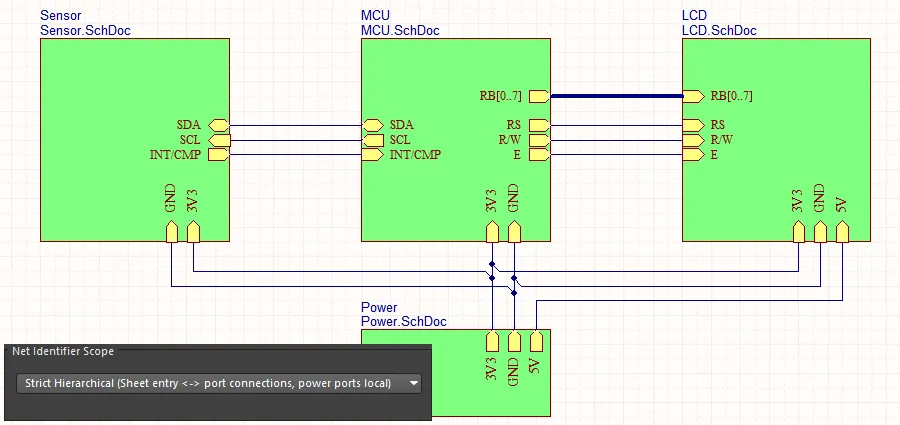 Net Identifier Scopeが
 Strict Hierarchicalに設定されている場合、すべての電源ネットは、それらが使用されるすべてのシートに配線する必要があります。
シート間でローカライズされた電源ネットを接続する
階層的な設計でローカライズされた電源ネットを接続する方法は、親シートのシートシンボルのシートエントリに子シートのポートからの他のネットと同じ方法です。ただし、電源ネットの場合、この技術は個々の電源ネットのみをサポートし、バスに束ねられた電源ネットはサポートしません( )。
)。
マルチチャネル設計を作成して、各チャネルにユニークな個別の電源ネットを供給したい場合(以下に示すようにRepeatステートメントを使用する場合)、これはサポートされています。設計が親から子への各シートエントリ-ポート組み合わせを通じて個々の電源ネットを接続しようとする限り、ネットリストは正しく行われます。
 ローカライズされた電源ネットは、階層を上下する個々のネットとして、マルチチャネル設計の各チャネルに配布できます。バスとしてではありません。
複数の電源ネットをバスに束ねて設計階層を通じて転送したい場合、それらのネットは標準ネットでなければならず、電源ポートを使用して接続することはできません。
電源ネットのローカライズ - 個別に
階層設計における特定の電源ネット(つまり、Net Identifier ScopeがHierarchicalに設定されている設計、またはトップシートにシートエントリを含む設計で、Net Identifier ScopeがAutomaticに設定されている場合 – ネット識別子スコープの設定についてさらに学ぶ)は、その回路図シート上のポートに電源ポートを配線することで、特定のシート上で局所化することもできます。

ここでは、3V3電源ネットがこのシートにのみ局所化されているため、親シート上でも手動で配線する必要があります。GNDと5Vのネットはグローバル電源ネットとして残ります。
電源ネットと隠された電源ピン
Altiumの古いバージョンの設計ソフトウェアには、隠された回路図コンポーネントピンの使用をサポートする機能とオプションが含まれていました。この機能は、設計が単一の電源ネットと単一のグラウンドネットを持っている場合に便利で、すべてのデバイスの電源ピンをそれぞれのネットに自動的に接続することができました。これは、これらのコンポーネントの電源ピンを回路図上に表示する必要がないため、多部品コンポーネントで最も人気がありました。
今日、電子設計は通常、複数の電源ネットとグラウンドネットを持っています。これらのネットは単に関連する電源ピンに配線されるだけでなく、電源供給は成功したボード設計の重要な側面となっています。
電源供給ネットワークの設計の性質が変わったため、コンポーネントピンを隠してソフトウェアが自動的に接続する必要性は減少し、ほとんどの設計者がこの慣行に反対するようになりました。このため、ソフトウェアはもはやピンを隠してネット名を事前に割り当てることをサポートしていません。この設計アプローチを使用する古いプロジェクトは、Altiumの最新バージョンの設計ソフトウェアで開かれたときにも正しくネットリストされます。
動的コンパイル
関連ページ: 設計プロジェクトの検証
2つのピンをワイヤで接続するとき、実際のネットを作成しているのではなく、設計意図を描いているだけです。ネットはプロジェクトがコンパイルされるまで作成されません。コンパイルは、コンポーネントとそれらの接続方法に関する詳細だけでなく、詳細なコンポーネントと設計のパラメトリック情報も抽出します。プロジェクトのコンパイルモデルは、統合データモデルとして参照されます。
Altium Designer 20.0以前のソフトウェアバージョンでは、プロジェクトを手動でコンパイルして統合データモデルを構築する必要がありました。それ以来、設計データモデルは、動的コンパイルを通じて各ユーザー操作後にインクリメンタルに更新され、動的データモデル(DDM)と呼ばれるものが作成されます。プロジェクトの手動コンパイルは関与せず、すべて自動的に行われます。設計の接続モデルは、動的コンパイルのおかげで、各ユーザー操作後にインクリメンタルに更新されます。設計プロジェクトにとって、自動コンパイルプロセスは3つの機能を実行します:
-
設計階層をインスタンス化します。
-
すべての設計シート間のネット接続を確立します。
-
設計の内部動的データモデル(DDM)を構築します。
これにより、行われた任意の設計変更がナビゲーターおよびプロジェクトパネルに直ちに反映されることが保証されます。
DDMとコンパイラ設定の間の論理的、電気的、およびドラフトエラーをチェックするには、プロジェクトを検証する必要があります。このコマンドは、メインメニューからProject » Validate Projectコマンドを選択するか、プロジェクトパネルのプロジェクトエントリを右クリックして、コンテキストメニューからValidate Projectコマンドを選択することでアクセスできます。
コンパイラによって検出された違反は、Messagesパネルに警告および/またはエラーとしてリストされます。コンパイラは、プロジェクトタイプに適用される場合、Project OptionsダイアログのError Reporting およびConnection Matrixタブで定義されたオプションを使用して、ソースドキュメントの違反をチェックします。
動的データモデル
ソフトウェアの基本要素は、統一データモデル(UDM)です。動的コンパイルの自動インスタンスを通じて、設計プロセスの中心に位置する単一で統合されたモデルが作成されます。モデル内のデータは、ソフトウェア内のさまざまなエディタやサービス、回路図やPCBを含む、アクセスおよび操作が可能です。さまざまな設計ドメインごとに別々のデータストアを使用するのではなく、UDMは、コンポーネントとその接続性を含む、設計のすべての側面からの情報を収容するように構造化されています。この単一で統合されたモデルは、動的設計コンパイルの結果として作成され、設計プロセスの中心に位置します。これは、プロジェクトが開かれた瞬間から統一データモデルが利用可能であり、追加の手動コンパイルを必要としないことを意味します - 真のダイナミックデータモデル(DDM)です。したがって、モデルはユーザー操作ごとにインクリメンタルに更新(コンパイル)されます。回路図設計から自由に配置、配線、再配置、名前変更、追加、削除が可能です。
PCB設計のコンパイルプロセスは、回路図およびPCBエディタの外部のコードによって管理されます。このアプローチにはいくつかの利点があり、最大の利点は、設計の統一データモデルが個々の回路図およびPCBエディタの外部に位置していることです。UDMには、設計内のすべてのコンポーネントの詳細な説明と、それらが互いにどのように接続されているかが含まれています。

ソフトウェアは、回路図とPCBを通じて接続データを管理します。
以下の場所と操作では、コンパイルが動的であるため、設計コンパイルに関して追加の手動操作は必要ありません:
-
ナビゲーターおよびプロジェクトパネル
-
ActiveBOM
-
ECOの実行
-
クロスプロービング
-
ネットカラーハイライト
-
ピンスワッピング
-
コンポーネントクロスリファレンス
動的コンパイル後にプロジェクトビューとナビゲーターパネルを更新するには、Refreshコマンドをプロジェクトおよびナビゲーターパネルの右クリックメニューから使用します。動的コンパイル後にプロジェクトビューとナビゲーターパネルを自動的に更新するには、Schematic.DynamicCompiler.Navigator.AutorefreshオプションをAdvanced Settingsダイアログで有効にします。
エラーチェックやPCBエディタへの転送の準備ができていない設計のセクションを隠すためにコンパイルマスクを配置します。準備ができたら、マスクを折りたたむコントロールをクリックして、コンパイルプロセスと設計転送に含める回路を表示します。
コンパイルマスクは設計指示と呼ばれるオブジェクトのクラスに属します。これらを使用して、ネットクラスのメンバーシップ、コンパイラが特定の違反を無視する場所の特定、差動ペアであるネットのグループの特定など、回路図に設計レベルの指示(方向)を追加します。コンパイルマスクのデモンストレーションのために画像にマウスを合わせてください。

では、設計を通じてネットを追跡するなど、統一データモデルとどのようにやり取りしますか?それはNavigatorパネルを通じて行います。
接続性の検討
パネルページ: Navigatorパネル
設計が大きく多くのシートにまたがっている場合、設計の接続性を追跡して確認するのが難しくなることがあります。このプロセスを支援するために、Navigatorパネルを使用できます。パネルは、コンパイルされた設計全体のビューを提供します。
パネルの使用方法の基本的なアプローチは次のとおりです:
-
パネルの上部にある  ボタンをクリックして設定ダイアログを開き、好みのHighlight Methodsを有効にすることで、ブラウジングの動作を設定します。または、パネル内の興味のあるオブジェクトを右クリックし、下の画像に示すようにメニューオプションを使用してナビゲーション動作を設定します。
-
Documents forパネルの領域で、ブラウジングの範囲を設定して、設計全体をブラウズするにはフラット化された階層を選択します。
-
リストのInstanceセクションでコンポーネントをクリックすると、そのコンポーネントにジャンプしたり、コンポーネントを展開して検索したり、ピンにジャンプしたりできます。
-
Net /Busセクションでネットまたはバスをクリックすると、そのネットまたはバスにジャンプします。
-
Altキーを押しながらクリックすると、回路図と PCB の両方でそのオブジェクトにジャンプします。
.")
Navigatorパネルでコンポーネントやネットをクリックして、そのコンポーネントやネットを特定し、設計を通じての接続性を追跡します。表示オプションにアクセスするには、右クリックします。画像上でカーソルをホバーすると、回路図とPCB上で同時にコンポーネントにナビゲートする様子が表示されます(PCBオブジェクトを含めるには、Navigatorパネルでクリックする際にAltキーを押し続けます)。
ボード上のコンポーネントのナビゲート
回路図とPCB上でコンポーネントを特定するだけでなく(Altキーを押し続けた場合)、NavigatorパネルからPCB上のピン/コンポーネント/ネット/バス/ハーネスを直接ナビゲートすることもできます。
例えば、回路図上でコンポーネントを特定するとき、その同じコンポーネントをPCB上でも特定できます。
これを行うには:

これらのオプションは、ナビゲーションとクロスセレクションの動作を設定します。
これで、回路図上でピン/コンポーネント/ネット/バス/ハーネスを選択すると、下の画像に示すように、それらのオブジェクトもPCB上で選択されます。

回路図上でコンポーネントとネットを選択すると、それらのオブジェクトもPCB上で選択されます。クロスセレクションはPCBから回路図へも機能します。
プロジェクト構造内のコンポーネントとネットの検索
パネルの構造をナビゲートして、関心のあるコンポーネントやネットを見つけ、そのオブジェクトをダブルクリックして、プロジェクトの回路図ドキュメント内のそのオブジェクトのインスタンスを表示します。PreferencesダイアログのSystem - Navigationページでオブジェクトのハイライト動作(ズーム、ディム、選択など)を指定します。

設計スペースで右クリックし、Clear Filterオプションを選択して、回路図またはPCBエディタでのオブジェクトのハイライト/選択を解除します。
プロジェクトオブジェクトのナビゲーションは、設計オブジェクトとそれらの関連データの詳細な階層構造を提供するNavigator panelでも利用可能です。System - Navigationの設定は、ProjectおよびNavigatorパネルの両方のオブジェクトハイライト動作を決定します。
接続のハイライト
Projectsパネルで選択されたオブジェクトの接続関係を表示する接続ナビゲーションオプション。パネルのオブジェクト階層リストで、例えばネットのエントリをダブルクリックすると、回路図内のその相互接続がハイライトされます。
プレビュー機能は、System – NavigationページのHighlight MethodsセクションのConnectivity Graphオプションによって有効にされます。選択されたオブジェクトに関連する電源オブジェクトの接続性も表示するには、追加のInclude Power Partsオプションを選択します。

グローバルネットのハイライト
設計全体のネット接続性は、ワイヤ上でネットを選択する際にAltキーを押し続けること(Alt+Click)により、すべての回路図でハイライトされます。ネットのすべての回路図インスタンスがハイライトされ、他のオブジェクトはディムされ、設計内の信号/電力の伝播を一つのシンプルなアクションで視覚的に示します。
ネットのハイライトは、空白をクリックすることでクリアされ、その動作はPreferencesダイアログのSystem - Navigation pageのHighlight Methods設定によって決定されます。Dimmingオプションのチェックを外すと、ネットハイライト機能が無効になることに注意してください。
クロスプロービングとクロスセレクション
Altium Designerは、1つのエディタから別のエディタに選択(クロス選択)できるだけでなく、クロスプローブもサポートしています。クロスプローブには、連続(ソースエディタに残る)とジャンプ先(ターゲットエディタにジャンプする)の2つのモードがあります。また、さまざまなパネルやダイアログ(MessagesパネルやEngineering Change Orderダイアログなど)からクロスプローブすることもできます。詳細については、 クロスプローブと選択のページを参照してください。
ネットの色の設定
メーンページ:ネットに色を適用する
回路図を読みやすくし、PCB エディタでネットと配線を操作しやすくするために、回路図の配線、PCB のネット、配線に色を適用できます。
ハイライト色は、下の画像に示されているように、View » Set Net Colorsサブメニューのコマンドを使用して、回路図エディタでネットやバスに適用できます。これらの色は、Update PCBコマンドを介していつでもPCBエディタに転送できます。
PCBエディタでは、Connection Linesのデフォルト色と可視性は、PCBのView ConfigurationパネルのSystem Colorsセクションで設定されます。このデフォルト色は、ネットが作成されるとき(回路図からの初期設計転送中)に適用されることに注意してください。このオプションが変更されても、既存の接続線の色は変わりません。
PCBエディタでは、各ネットに適用された色は、PCBパネルのネットモードで表示されます。下の画像の右下隅に示されているように、ネット名の横のチェックボックスの背後にある色を探します。
色は常に未配線のネット(接続線)に適用されます。配線済みのネットに色を表示するには、PCBパネルでネット名の横のチェックボックスを有効にし、Preferencesダイアログのボードインサイトカラーオーバーライドページで表示オプションを設定します。下の画像では、オーバーライド色の基本パターンがSolidに設定され、ズームアウト動作がOverride Color Dominatesに設定されています。
 回路図で適用されたネットカラーは、Update PCBコマンドによってPCBに転送されます。PCBカラーオーバーライド機能を設定して、ボード上での表示方法を制御します。
F5を押して、回路図とPCBエディタの両方でネットカラーオーバーライド機能をオン/オフに切り替えます。画面のリフレッシュ(End)も必要になる場合があります。
PCBネットの色を変更する
回路図の配線に色を適用してPCBに転送することは常に可能ではありません。この状況では、PCBエディタで接続線と配線に色を適用することができます。設計が転送された後にネットの色を変更するには、PCBパネルのNetsモードでネット名をダブルクリックします。個々のネットの色は、Edit Netダイアログで編集できます。
複数のネットの色を変更するには、PCBパネルのNetsモードを使用します:
-
複数のネットクラスまたは個々のネットを複数選択するには、標準のWindowsマルチセレクト技術(Shift+クリックまたはCtrl+クリック)を使用します。
-
選択したオブジェクトを右クリックし、コンテキストメニューからChange Net Colorコマンドを選択して、選択したネットに新しい色を割り当てます。
-
もう一度右クリックし、Display Override » Selected Onを選択して、選択したネットのカラーオーバーライド機能を有効にします。

接続線の色を変更し、表示オーバーライド機能を有効にすることで、ネットの可視性を向上させます

