Определение и управление правилами проектирования
Диалоговое окно PCB Rules and Constraints Editor открывается с помощью команды Design » Rules в главном меню.
Команды Rules нет в меню Design? Проверьте, доступно ли у вас диалоговое окно PCB Rules and Constraints Editor — подробнее.
Диалоговое окно PCB Rules and Constraints Editor содержит два раздела:
-
Дерево слева содержит список различных категорий правил. Разверните категорию, чтобы отобразить доступные отдельные типы правил. Разверните тип правила, чтобы отобразить все правила этого типа, которые определены в данный момент.
Дополнительные сведения о доступных типах правил и их ограничениях см. на странице PCB Design Rule Types и ее подстраницах.
-
Правая часть диалогового окна отображает информацию в зависимости от того, что выбрано в дереве в данный момент: либо сводку определенных правил выбранного типа или категории, либо все определенные правила всей системы, либо, если выбрано конкретное правило, ограничения для этого правила.
-
Щелкните корневую папку, чтобы открыть в основной области редактирования диалогового окна сводный список всех конкретных правил, определенных для всех типов правил проектирования во всех категориях.
-
Щелкните папку категории, чтобы открыть сводный список всех конкретных правил, определенных для всех связанных типов правил этой категории.
-
Щелкните папку типа правила, чтобы открыть сводный список всех конкретных правил, определенных для этого типа.
В сводном списке каждое правило указывается со следующей информацией:
-
Name - имя правила.
-
Priority - текущий приоритет правила.
-
Enabled - включено или отключено это правило в данный момент (щелкните, чтобы переключить состояние). Отключенное правило в сводном списке будет показано серым цветом.
-
Type - тип правила.
-
Category - категория правила, к которой оно относится.
-
Scope - область действия правила (то есть к какому объекту или объектам оно применяется).
-
Attributes - атрибуты ограничений, заданные для этого правила.
Щелкните запись конкретного правила в панели дерева папок (или дважды щелкните его запись в сводном списке), чтобы открыть элементы управления его определением:
-
Name - текущее имя правила. При необходимости его можно изменить.
-
Comment - это поле отображает любой комментарий, добавленный к правилу, например содержательное описание того, для чего используется правило.
-
Unique ID - уникальный идентификатор правила. Каждое правило само по себе является объектом проекта и, следовательно, представляет собой осязаемую единицу данных. Использование ID обеспечивает уникальность. Особенно важен Unique ID для правила, созданного в области схемы. При добавлении параметров правил проектирования к объектам на схеме каждому параметру правила присваивается уникальный ID. Те же ID присваиваются соответствующим правилам проектирования, создаваемым на PCB. Благодаря этому Unique ID ограничения правила можно редактировать как со стороны схемы, так и со стороны PCB, а изменения будут переданы при синхронизации.
-
Test Queries - нажмите, чтобы открыть диалоговое окно Test Queries Result dialog, в котором показано количество объектов, затрагиваемых правилом, с учетом заданных вами специализаций правила. Это позволяет увидеть, есть ли объекты, соответствующие запросу, а также проверить, соответствует ли набор объектов, затронутых фильтрами и правилами, вашим ожиданиям.
-
Rule Scoping Controls - эта область содержит элементы управления для определения области действия правила с точки зрения объектов, к которым или между которыми оно применяется.
-
Constraints - эта область диалогового окна показывает ограничения, применимые к редактируемому типу правила. Используйте различные элементы управления для настройки этих ограничений по мере необходимости. Нажмите F1 над областью ограничений, чтобы открыть страницу для этого типа правила в разделе документации PCB Design Rule Types.

Диалоговое окно PCB Rules and Constraints Editor — центральное место управления правилами проектирования.
-
Поисковый механизм диалогового окна позволяет использовать его в простом режиме поиска, вводя соответствующие ключевые слова Name, Type, Category или Attribute в основное поле Search.
-
Нажмите кнопку Switch to Document View в нижней части диалогового окна, чтобы открыть Constraints Editor, который представляет собой интерактивный документ Rules.
Просмотр правил проектирования
Новая плата, создаваемая программой по умолчанию, будет содержать правила, которые нужны не в каждом проекте, а многие другие правила проектирования потребуется скорректировать в соответствии с требованиями вашего проекта. По этой причине очень важно просматривать правила проектирования. Это можно сделать в PCB Rules and Constraints Editor. Выберите Design Rules в верхней части дерева слева, затем просмотрите столбец Attributes, чтобы увидеть все правила и быстро найти те, значения которых нужно изменить.
При создании новой платы в нее включаются стандартные правила проектирования, которые могут быть не нужны для вашего проекта. Лишние правила можно отключить, щелкнув по записи Design Rules или по записи конкретной категории в PCB Rules and Constraints Editor и отключив правила (снимите флажки в столбце Enabled).
Плата по умолчанию также использует имперские единицы измерения. Если в вашей плате используются метрические единицы, многие значения правил, например расширение Soldermask, изменятся с округленных значений вроде 4mil на 0.102mm, а значение по умолчанию для Minimum Solder Mask Sliver изменится с 10mil на 0.254mm. Хотя младший разряд, например 0.002mm, несущественен при формировании выходных данных, при желании вы можете отредактировать эти параметры в правилах проектирования.

При просмотре правил проектирования обратите внимание, что порядок столбцов при необходимости можно изменить.
Стандартные правила проектирования
При создании нового документа PCB в него включается ряд стандартных правил, которые должны существовать для корректной работы системы Design Rule Check. Если стандартное правило удалено, оно автоматически создается заново при закрытии PCB Rules and Constraints Editor. Если есть правила проектирования, которые вы не хотите использовать, правильный способ работы с ними — отключить их.
Чтобы отключить правило, переключите соответствующий параметр Enable для этого правила в одном из сводных списков справа в диалоговом окне PCB Rules and Constraints Editor. Отключенное правило отображается «серым». Подробнее о отключении правил проектирования.
 Используйте параметр Enable, чтобы отключить ненужное правило. Отключенное правило отображается «серым».
Значения правил по умолчанию внутренне определяются в mil и могут не подходить для ваших проектов. Чтобы использовать собственные стандартные правила и значения, вы можете:
-
создать и использовать шаблон проекта, или
-
создать подходящий пустой файл платы с настроенными нужным образом правилами и взять копию этой платы для нового проекта, или
-
экспортировать свой набор шаблонных правил в файл PCB Rule (*.RUL), а затем импортировать эти правила в текущий проект платы. Подробнее о экспорте и импорте правил проектирования.
Нажмите кнопку Create Default Rules, чтобы заново сформировать стандартный набор правил проектирования для PCB. Если вы удалили правила, вы можете вернуть список стандартных правил, нажав эту кнопку. Если стандартное правило было изменено, оно не будет сброшено или заменено.
Создание нового правила
Чтобы добавить новое правило проектирования из диалогового окна PCB Rules and Constraints Editor, перейдите к нужному типу правила в дереве слева и выберите его, затем нажмите кнопку New Rule под сводным списком правил или щелкните правой кнопкой мыши по нужному типу правила и выберите New Rule в контекстном меню.
Новое правило будет добавлено в дерево папок, а также появится в сводном списке для этого типа правил. Имя правила будет отображаться полужирным, чтобы показать, что оно новое и еще не было «применено».

Пример создания нового правила проектирования PCB.
При добавлении нового правила ему сначала присваивается имя по умолчанию на основе конкретного типа правила. Например, если вы добавите новое правило Clearance, именем по умолчанию будет Clearance. Если это имя по умолчанию не изменить, добавление еще одного нового правила того же типа приведет к созданию правила с тем же именем и увеличенным числовым суффиксом (то есть Clearance_1, Clearance_2 и т. д.).
Когда новое правило создается для определенного типа правил, ему автоматически присваивается приоритет 1 (наивысший приоритет). Если уже существуют другие правила этого типа, их приоритеты соответственно смещаются на один вниз. После этого они считаются измененными — даже если фактически не изменялись на уровне области действия/ограничений. Поэтому все существующие правила этого типа будут отображаться как измененные (полужирным со звездочкой).
Чтобы получить доступ к атрибутам области действия и ограничений правила, либо щелкните запись правила в области дерева папок, либо дважды щелкните его запись в сводном списке. Главное окно редактирования диалога изменится и предоставит доступ к элементам управления для задания области действия и ограничений этого правила.

Доступ к подробным элементам управления правилом, включая область действия и ограничения.
Чтобы полностью определить новое правило:
-
Дайте правилу осмысленное имя, чтобы его было легко идентифицировать.
-
Определите область действия правила, выбрав параметры из раскрывающихся списков или введя запрос (или запросы для бинарного правила).
-
Задайте ограничения правила.
-
Установите приоритет правила.
Использование мастера правил для создания нового правила
Новое правило также можно создать с помощью Design Rule Wizard. Доступ осуществляется напрямую командой Design » Rule Wizard или нажатием кнопки Rule Wizard внизу диалогового окна PCB Rules and Constraints Editor.
Кнопка Rule Wizard будет недоступна, если в существующих правилах есть изменения, которые еще не были «применены».
Используйте страницы Wizard для создания нового правила проектирования. Шаги следующие:
-
Выберите нужный тип правила и задайте ему осмысленное имя (и комментарий, если требуется).
-
Определите область действия правила. У вас будет возможность дополнительно уточнить область действия с помощью встроенной в мастер версии Query Builder.
-
Установите приоритет правила.
Если на последней странице Wizard включен параметр Launch main design rules dialog, диалоговое окно PCB Rules and Constraints Editor откроется после нажатия кнопки Finish. Это диалоговое окно можно использовать для редактирования ограничений только что созданного правила.

Используйте Design Rule Wizard для упрощения создания правил.
Дублирование существующего правила
Чтобы быстро создать идентичную копию существующего правила, используйте функцию дублирования. К этой функции можно получить доступ двумя способами:
-
Используйте дерево слева, чтобы перейти к нужному существующему правилу, щелкните правой кнопкой мыши и выберите Duplicate Rule в контекстном меню.
-
Перейдите к конкретному типу правила в дереве слева, выберите правило для дублирования в сводном списке справа, затем нажмите кнопку Duplicate Rule под списком.

Упростите создание похожих правил с помощью функции дублирования правил.
Дублированное правило будет называться так же, как исходное, но с добавлением суффикса (например, _1) для различения. Его определение (область действия, ограничения и т. д.) будет идентичным исходному. Что касается приоритета, ему будет присвоен следующий приоритет ниже, чем у исходного правила. Так, например, если исходное правило имеет приоритет 1, дубликату будет присвоен приоритет 2.
Создание правила из панели PCB Filter
Поскольку область действия правила проектирования задает целевой набор объектов проекта, часто бывает проще (и быстрее) сначала определить эти объекты, а затем создать правило проектирования, которое на них нацелено. Панель PCB Filter panel предоставляет возможность создавать правило проектирования, область действия которого использует текущее выражение запроса, заданное в панели. Поэтому вместо того чтобы пытаться представить, на какие объекты нацелено выражение запроса might, используйте панель PCB Filter для проверки и настройки выражения запроса до тех пор, пока не будут отфильтрованы только нужные объекты. После этого, создав правило, использующее данное выражение запроса, вы гарантированно нацелитесь на правильный набор объектов.
Чтобы добавить новое правило проектирования:
-
Нажмите кнопку Create Rule. Появится диалоговое окно Choose Design Rule Type. В этом диалоговом окне перечислены все категории и типы правил, доступные в документе PCB.
-
Выберите тип создаваемого правила, затем нажмите OK (или просто дважды щелкните по записи).
-
Появится диалоговое окно PCB Rules and Constraints Editor. Будет создано правило выбранного типа, и отобразится главное окно редактирования этого правила, готовое для задания конкретных ограничений. Для области действия правила будет установлен параметр Custom Query, а выражение запроса из панели PCB Filter будет соответствующим образом подставлено в область запроса.
-
При необходимости измените имя правила и его ограничения. Также измените его приоритет, если нужно (по умолчанию ему будет присвоен наивысший приоритет).

Создайте новое правило проектирования непосредственно из панели PCB Filter — выражение запроса фильтра используется как область действия правила.
Повторное использование ранее созданных выражений запроса
Со временем в процессе трассировки различных плат будет создано немало полезных выражений запросов. Обычно такие запросы требуется применять и повторно применять не только в рамках одного проекта но и в разных проектах. Для этого PCB Filter panel поддерживает работу с Historical и Favorite запросами.
Когда запрос вводится и применяется из панели, он добавляется в «список истории» запросов. Кроме того, этот запрос можно добавить в «список избранных» запросов, нажав кнопку Add To Favorites. Используйте кнопки History и Favorites на панели, чтобы открыть соответствующие одноименные вкладки в диалоговом окне Expression Manager dialog и просмотреть эти списки.

Получайте доступ к истории примененных выражений запросов и формируйте список избранных выражений для многократного повторного использования.
Чтобы использовать выражение из любого из этих списков, дважды щелкните по его записи или выберите запись и нажмите кнопку Apply Expression. Диалоговое окно Expression Manager закроется, а выражение будет загружено в область Filter панели PCB Filter.
Эта функциональность упрощает (и ускоряет) создание правил с необходимой областью действия: извлеките выражение запроса из истории или избранного, проверьте, что оно по-прежнему нацелено на требуемый набор объектов (примените фильтр), а затем создайте правило, использующее это выражение в своей области действия, как описано в предыдущем разделе.
Задание области действия правила проектирования
PCB-редактор Altium Designer работает в среде, управляемой правилами. Требования к проекту обеспечиваются четко определенным набором правил проектирования, которые совместно задают ограничения для платы. Правила проектирования нацелены на определенные объекты в проекте. Чтобы система правил PCB понимала, к каким именно объектам применяется конкретное правило, ей необходимо знать область действия этого правила, то есть границы его применения. Scopingили нацеливание правила, выполняется в диалоговом окне PCB Rules and Constraints Editor.
Стандартные правила проектирования, а также новое добавленное правило, имеют стандартную область действия All, что означает, что они будут применяться к all objects на плате. С помощью раскрывающегося списка можно быстро настроить простую область действия правила.

Задайте область действия правила проектирования, чтобы определить, к каким объектам проекта оно применяется.
Вместо ограничения заранее определенным списком возможных вариантов нацеливания каждое правило проектирования можно точнее ограничить, написав так называемый Query.
Чтобы ввести запрос, установите первый раскрывающийся список Where The Object Matches в значение Custom Query. В нем отобразится запрос, который в данный момент используется механизмом правил для этого правила на основе текущих настроек раскрывающихся списков.
По сути, запрос — это инструкция для программного обеспечения, определяющая набор целевых объектов проекта. Запросы записываются с использованием ключевых слов запросов. Так же, как запрос можно записать в панели Filter для поиска определенного набора объектов, его также можно записать для определения объектов, на которые нацелено каждое правило. Например:
InNet('VBAT') And OnLayer('Bottom Layer')
Если этот запрос использовать как область действия для правила Width rule, то при трассировке цепи VBAT и переключении на нижний слой ширина дорожки будет автоматически изменяться на ширину, заданную в ограничениях этого правила. Кроме того, при запуске проверки правил проектирования любая трассировка цепи VBAT на нижнем слое должна будет иметь указанную ширину, иначе это будет отмечено как нарушение.

Задание области действия правил основано на системе запросов. Используйте параметр Custom Query, чтобы просмотреть текущий запрос и при необходимости изменить его с помощью ключевых слов запросов.
В зависимости от того, является правило унарным или бинарным, потребуется соответственно определить одну или две области действия. Для унарного правила проектирования будут доступны элементы управления для задания одной области действия правила. Используйте параметры в области Where The Object Matches, чтобы помочь сформировать выражение запроса, которое будет отображаться в области справа. Для бинарного правила проектирования будут доступны элементы управления для Where The First Object Matches и Where The Second Object Matches , чтобы определить обе области действия правила. Используйте доступные раскрывающиеся списки каждого из них, чтобы помочь сформировать выражение запроса. Элементы управления одинаковы независимо от того, задается одна или две области действия правила.
Когда изменяются позиционные обозначения компонентов PCB или имена полигонов, ссылки в правилах проектирования, использующих пользовательские запросы, обновляются автоматически. Запросы в правилах проектирования, ссылающиеся на позиционные обозначения компонентов PCB, изменяются, когда позиционные обозначения переаннотируются, обновляются через ECO, или редактируются вручную на плате.
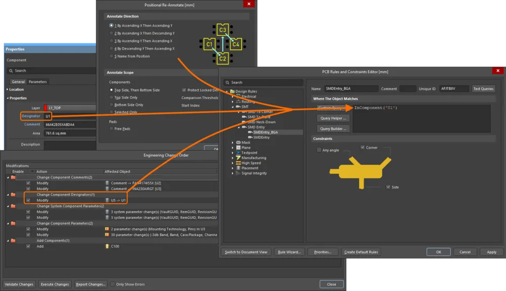
Обновление запросов правил при изменении позиционных обозначений компонентов доступно, когда в диалоговом окне Advanced Settings dialog включен параметр PCB.Rules.UpdateQueryOnComponentDesignatorChange.
Обновление запросов правил при изменении имен полигонов доступно, когда в диалоговом окне Advanced Settings dialog включен параметр PCB.Rules.UpdateQueryOnPolygonNameChange.
Если в запросе есть синтаксическая ошибка, правило будет считаться недействительным и будет выделено красным цветом в диалоговом окне PCB Rules and Constraints Editor как в дереве правил слева, так и в любом итоговом представлении (категория правила или тип правила), где это правило отображается. Кроме того, текст типа правила и категории правила также отображается красным цветом в дереве правил слева. Поэтому, если вы свернули область дерева правил, содержащую недействительное правило, вы все равно будете уведомлены об этом на более высоком уровне иерархии. Предупреждающее сообщение также появится, если вы попытаетесь закрыть диалоговое окно. Область действия правила с синтаксической ошибкой может значительно замедлить процесс анализа Online и Batch DRC. Обязательно исправляйте все области действия правил, которые синтаксически некорректны.
Параметры задания области действия
Предусмотрены простые параметры задания области действия, позволяющие быстро создавать запросы области действия. Выберите один из параметров в первом раскрывающемся поле и, при необходимости, используйте последующие раскрывающиеся списки для выбора подходящей цели, например Net, Layer, Footprint, Package и т. д. Представленные параметры задания области действия зависят от типа правила.

Быстро создавайте запрос с помощью простых параметров задания области действия.
Примеры простых параметров задания области действия:
-
All — создать запрос области действия, нацеленный на все объекты проекта.
-
Net — создать запрос области действия, нацеленный на все объекты в определенной цепи. Появится дополнительный раскрывающийся список, в котором можно выбрать нужную цепь из списка доступных вариантов, включая No Net.
-
Net Class — создать запрос области действия, нацеленный на все объекты в определенном классе цепей. Появится дополнительный раскрывающийся список, в котором можно выбрать нужный класс цепей из списка доступных вариантов, включая All Nets.
-
Layer — создать запрос области действия, нацеленный на все объекты на определенном слое. Появится дополнительный раскрывающийся список, в котором можно выбрать нужный слой из списка доступных вариантов.
-
Net and Layer — создать запрос области действия, нацеленный на все объекты в определенной цепи и на определенном слое. Появятся два дополнительных раскрывающихся списка, в которых можно выбрать нужные цепь и слой.
Даже если область действия правила задается с помощью простых параметров, запрос все равно создается. Запрос отображается, если выбрать Custom Query в первом раскрывающемся поле.
Параметр Custom Query позволяет написать собственный, возможно более сложный, но и более точный запрос. Вы можете ввести свой конкретный запрос для области действия правила непосредственно в область запроса справа. Кроме того, для помощи в создании логических выражений запросов доступны две функции. Это Query Builder и Query Helper. Они могут быть полезны, если вы не уверены в синтаксисе запроса или в том, какие ключевые слова доступны.

Используйте параметр Custom Query для создания более сложного выражения запроса.
-
Если вы хорошо знакомы с Query Language, то можете ввести выражение запроса непосредственно в область запроса. Также можно вставить выражение запроса из любимого редактора напрямую в эту область или скопировать выражение запроса во внешний редактор, либо даже вставить запрос во вторую область действия бинарного правила. Это особенно полезно, если обе области действия сложны и различаются лишь незначительно.
-
Query Builder — это более простой способ построения запроса, использующий чувствительные к контексту типы условий и значения, которые позволяют собирать запрос только из релевантных «строительных блоков». Для расширенного построения запросов с полным указанием ключевых слов и синтаксиса операторов используйте Query Helper.
Задание области действия правила с помощью Query Builder
Когда выбран параметр Custom Query, нажмите кнопку  , чтобы открыть диалоговое окно Building Query from Board dialog, которое позволяет создать запрос для нацеливания на конкретные объекты в документе проекта путем простого построения строки условных выражений.
Левая часть диалогового окна используется для задания условия(ий), необходимых для выбора требуемого набора объектов. Каждое условие состоит из Condition Type и Condition Value. Выпадающие списки для них заполняются записями, относящимися соответственно к построению области действия для текущего типа правила и значениям для выбранного типа условия.
По мере задания условия в правой части диалогового окна отображается предварительный просмотр формируемого запроса. Условия можно объединять с помощью AND и/или OR, а также задавать приоритеты (с использованием скобок/отступов) для уточнения целевого набора объектов. Когда выражение запроса определено нужным образом, нажатие OK загрузит это выражение в область запроса диалогового окна PCB Rules and Constraints Editor.
Обратите внимание, что при отображении в диалоговом окне PCB Rules and Constraints Editor в начало и конец выражения запроса соответственно добавляются дополнительные открывающая и закрывающая скобки.

Используйте Query Builder для построения логического выражения запроса с помощью серии условных операторов.
Задание области действия правила с помощью Query Helper
Когда выбран параметр Custom Query, нажмите кнопку  , чтобы открыть диалоговое окно Query Helper. Базовый Query Engine анализирует проект PCB и выводит список всех доступных объектов вместе с общими ключевыми словами для использования в запросах.
Работа с Query Helper довольно интуитивна, особенно если разделить ее на три отдельные области, как показано на изображении ниже:

Пример сложного запроса, заданного с помощью Query Helper.
Эти области:
-
Query Region – используйте эту область диалогового окна для составления выражения запроса. Выражение, которое в данный момент применяется к области действия правила, по умолчанию будет доступно в этой области при открытии диалогового окна. Вы можете вводить текст непосредственно в этой области; в качестве подсказки будет появляться контекстно-зависимый «список предложений» с возможными ключевыми словами или объектами.
-
Operators – эта область диалогового окна предоставляет набор математических и логических операторов для использования при построении выражения. Нажмите кнопку, чтобы добавить соответствующий оператор в текущую позицию курсора в выражении запроса в области Query выше.
-
Categories, Keywords and Objects – эта область диалогового окна предоставляет доступ к доступным PCB Functions, PCB Object Lists и System Functions, которые можно использовать для создания выражения запроса. Щелчок по подкатегории в любой из этих трех областей отобразит список соответствующих ключевых слов или объектов в области справа. Найдите ключевое слово или объект, который нужно использовать в строке запроса, затем дважды щелкните по соответствующей записи; она будет вставлена в текущую позицию курсора в выражении запроса в области Query выше.
Используйте кнопку  (в левом нижнем углу диалогового окна), чтобы проверить синтаксическую корректность выражения. Когда выражение запроса определено нужным образом, нажатие OK загрузит это выражение в область запроса диалогового окна PCB Rules and Constraints Editor.
При использовании диалогового окна
Query Helper для построения запроса щелчок по ключевому слову в одном из доступных списков и нажатие
F1 откроют документацию по данному ключевому слову в
Query Language Reference.
Приоритет операторов в выражениях запросов
Прежде чем покинуть этот раздел, стоит рассмотреть порядок приоритетов, установленный для операторов, используемых в логических выражениях Query. В конце концов, без такого знания выражение может не выбрать нужные объекты.
Скобки имеют наивысший приоритет в рамках заданного порядка приоритетов для различных операторов, который определяет, как запросы интерпретируются программой (когда пользователь не указал скобки). Последовательность этого порядка от высшего к низшему следующая:
-
Скобки
-
Not
-
^, *, /, Div, Mod, And
-
+, -, Or, Xor
-
=, <>, <, >, <=, >=
-
&&, ||
Этот порядок приоритетов похож на используемый в языках типа Pascal. Неоднозначности разрешаются при вычислении слева направо. Скобки вычисляются изнутри наружу, а операторы одного уровня — слева направо.
Настоятельно рекомендуется использовать скобки всякий раз, когда есть хоть малейшая вероятность того, что запрос может быть интерпретирован неверно. Щедрое использование скобок устраняет сомнения и делает получившиеся запросы более понятными для других.
Приоритизация правил
Чтобы упростить процесс определения правил и управления ими, предлагается задавать общие правила, охватывающие широкие требования, а затем переопределять их более конкретными правилами в конкретных ситуациях. Чтобы это было возможно, необходимо иметь возможность расставлять приоритеты правил, указывая, какое из них следует использовать, когда объект подпадает под несколько правил одного типа.
Например, чтобы задать наиболее часто используемую ширину трассировки на плате, определите одно правило, которое применяется ко всем цепям на плате. Затем это правило можно переопределить для конкретной цепи (или даже для класса цепей), добавив другое правило того же типа, но с более высоким приоритетом.
Другим примером могут быть требования к паяльной маске. Здесь можно определить одно правило маски, которое распространяется на все контактные площадки и переходные отверстия на плате, а затем переопределить его для площадок в конкретном типе посадочного места. При необходимости это правило для конкретного посадочного места можно дополнительно переопределить для конкретной площадки в этом посадочном месте.
Важный аспект управления правилами — обеспечение корректной установки всех приоритетов. При создании нового правила ему по умолчанию присваивается наивысший приоритет. Используйте кнопку Priorities в нижней части диалогового окна PCB Rules and Constraints Editor, чтобы настроить приоритеты в диалоговом окне Edit Rule Priorities.

Изменение приоритетов правил в диалоговом окне Edit Rule Priorities.
Изначально в диалоговом окне будут перечислены все экземпляры правил для того типа правила, который в данный момент выбран в диалоговом окне PCB Rules and Constraints Editor. Используйте поле Rule Type, чтобы изменить тип правила и вывести список конкретных правил, определенных для этого типа. Заданные правила перечислены в порядке текущего приоритета — от 1 (наивысший приоритет) и ниже. Выберите запись правила и используйте кнопки Increase Priority и Decrease Priority, чтобы переместить его соответственно вверх или вниз в порядке приоритетов.
При добавлении нового правила к типу правила, который уже содержит одно или несколько существующих правил, его приоритет будет установлен в 1 (то есть наивысший приоритет). При дублировании правила копии присваивается приоритет ниже исходного правила.
Можно настроить несколько правил одного типа. Может случиться, что объект проекта подпадает под более чем одно правило с одинаковой областью действия. В этом случае возникает конфликт. Все конфликты разрешаются настройкой приоритета. Система проходит по правилам от наивысшего приоритета к низшему и выбирает первое, выражение(я) области действия которого соответствуют проверяемому объекту(ам). Есть одно исключение: к объектам могут применяться несколько правил проектирования Matched Length, и тогда к этим объектам применяются все правила.
Изменение существующих правил
Правила, разумеется, можно изменить в любое время. Более того, для получения окончательного рабочего набора правил часто требуется внести несколько ключевых уточнений тут и там. Обычно это касается области действия, чтобы гарантировать, что соответствующие правила «подхватывают» нужные объекты проекта так, как требуется. Выберите существующее правило в диалоговом окне PCB Rules and Constraints Editor и внесите необходимые изменения в его область действия и атрибуты ограничений.
Изменения, внесенные в существующие определения правил, подсвечиваются как в панели дерева папок, так и в соответствующих сводных списках. Такие записи отличаются тем, что имя правила становится полужирным, а справа от имени отображается звездочка. Звездочка указывает на то, что правило является существующим и было изменено, а не только что созданным (которое отображается полужирным без звездочки).

Пример существующего правила, которое было изменено. Для обозначения изменения используется звездочка, а имя правила выделяется полужирным.
Когда для определенного типа правила создается новое правило, ему автоматически присваивается приоритет 1. Если уже существуют другие правила этого типа, их приоритеты будут соответственно сдвинуты (понижены) на единицу. После этого они считаются измененными, даже если их область действия/ограничения не изменялись напрямую. Поэтому все такие существующие правила этого типа будут отображаться как измененные (полужирным со звездочкой).
Пометка недействительных правил
Если система определит правило как недействительное — например, из-за проблемы с выражением запроса в области действия или из-за недопустимого значения ограничения, — оно будет помечено как недействительное. Такое правило будет выделено красным цветом в диалоговом окне PCB Rules and Constraints Editor как в дереве правил слева, так и в любом сводном представлении (категория правил или тип правила), где это правило отображается. Кроме того, текст типа правила и категории правил также отображается красным цветом в дереве правил слева. Поэтому, даже если вы свернули область дерева правил, содержащую недействительное правило, вы все равно будете предупреждены об этом на более высоком уровне иерархии. Также появится предупреждающее сообщение, если вы попытаетесь закрыть диалоговое окно.
Область действия правила с синтаксической ошибкой может значительно замедлить анализ Online и Batch DRC, поэтому обязательно исправляйте все области действия правил, которые синтаксически некорректны.

Пример того, как система помечает недействительное правило проектирования; в данном случае это ошибочное выражение запроса области действия.
Отключение правил
В управляемой правилами среде PCB-редактора этого программного обеспечения нередко формируется довольно внушительный и полный набор правил, позволяющий успешно задавать ограничения для ваших плат. По тем или иным причинам в какой-то момент может потребоваться отключить некоторые правила; возможно, они не относятся к рассматриваемой плате или их нужно временно отключить, чтобы снизить нагрузку на Design Rule Checker (и, как следствие, повысить его производительность!). Отключение — это хороший способ сохранить такие правила на случай, если они снова понадобятся в будущем.
Чтобы отключить правило, переключите соответствующую опцию Enable для этого правила в одном из соответствующих сводных списков в правой части диалогового окна PCB Rules and Constraints Editor. Отключенное правило также будет отображаться «серым».

Пример отключенных правил, отображаемых серым шрифтом в сводном списке.
Правила также можно отключать/включать непосредственно из панели
PCB Rules And Violations panel. Переключите связанную с правилом опцию
On. Это отразится в опции
Enable данного правила в диалоговом окне
PCB Rules and Constraints Editor.
Удаление правил
Чтобы удалить одно правило проектирования из диалогового окна PCB Rules and Constraints Editor:
-
Используйте дерево слева, чтобы перейти к нужному существующему правилу, щелкните правой кнопкой мыши и выберите Delete Rule в контекстном меню.
-
Перейдите к конкретному типу правила в дереве слева, затем выберите правило, которое нужно удалить, в сводном списке справа. Затем нажмите кнопку Delete Rule(s) под списком.
Имя правила будет отображаться жирным с зачеркиванием, чтобы показать, что это удаление, которое еще не было «применено».

Удаление одного правила.
-
Если определенное правило проектирования больше не требуется, но может снова понадобиться в будущем, вместо удаления его можно просто отключить. Для этого переключите соответствующую опцию Enable для правила в одном из соответствующих сводных списков в правой части диалогового окна PCB Rules and Constraints Editor.
-
Несколько правил можно удалить одним действием из представления сводного списка. Для этого выберите правила для удаления (поддерживаются стандартные сочетания клавиш Shift+click и Ctrl+click), затем нажмите кнопку Delete Rule(s) под списком.
-
Для работы системы проверки правил проектирования должны присутствовать определенные правила; если одно из таких правил будет удалено (так что правил этого типа не останется), оно будет автоматически создано заново. Узнайте больше о правилах проектирования по умолчанию.
Для многих типов правил при создании нового PCB-документа создаются правила по умолчанию. Аналогично, если все конкретные правила одного из таких типов будут удалены, правило по умолчанию будет автоматически добавлено снова при следующем открытии диалогового окна PCB Rules and Constraints Editor. Кроме того, правила по умолчанию можно создать заново, нажав кнопку Create Default Rules в нижней части диалогового окна.
Экспорт и импорт правил
Правила проектирования можно экспортировать из диалогового окна PCB Rules and Constraints Editor и импортировать в него. Это позволяет сохранять и загружать избранные определения правил между разными проектами.
-
To export – щелкните правой кнопкой мыши в любом месте дерева слева в диалоговом окне и выберите Export Rules. Откроется диалоговое окно
 Choose Design Rule Type dialog, в котором можно выбрать правило(а) проектирования для экспорта. В открывшемся диалоговом окне Export Rules to File можно задать имя файла .rul и выбрать его расположение. Экспортированные правила сохраняются в файле правил PCB (
*.rul).
-
To import – щелкните правой кнопкой мыши в любом месте дерева слева в диалоговом окне и выберите Import Rules. Откроется диалоговое окно Choose Design Rule Type dialog, в котором можно выбрать правило(а) проектирования для импорта. В открывшемся диалоговом окне Import File укажите файл .rul для импорта.
При импорте, если правила выбранного типа уже существуют, будет предложена возможность очистить существующие правила перед импортом. Нажатие Yes приводит к удалению всех существующих правил этого типа с последующей заменой правилами из файла .rul. Нажатие No сохранит существующие правила. Однако если существующие и импортируемые правила имеют одинаковые имена, импортированные правила перезапишут существующие.
Отчеты по правилам проектирования
Отчет по текущим определенным правилам проектирования можно сформировать из диалогового окна PCB Rules and Constraints Editor. Отчет может охватывать все категории правил, конкретную категорию правил или конкретный тип правила — в зависимости от выбранного элемента в дереве папок. Отчет можно сформировать следующим образом:
-
Откройте нужный сводный список, щелкните правой кнопкой мыши и выберите команду Report в контекстном меню либо нажмите кнопку Report под списком.
-
Щелкните правой кнопкой мыши по соответствующему элементу в дереве папок и выберите команду Report в контекстном меню.
Откроется диалоговое окно Report Preview, в котором уже будет загружен соответствующий отчет. Используйте это диалоговое окно, чтобы просмотреть отчет с помощью различных элементов управления страницей/масштабом перед тем, как в итоге экспортировать его в файл или распечатать.

Создание отчета по правилам PCB.
Options and Controls of the Report Preview Dialog
-
Preview Window - в основной области этого диалогового окна отображается предварительный просмотр созданного отчета. Отчетом можно управлять с помощью различных элементов управления под окном и в меню, открываемом правой кнопкой мыши.
Используйте полосы прокрутки для перемещения по горизонтали или вертикали на увеличенной странице.
-
Page x of x - первое x — это текущая просматриваемая страница; второе x — общее число страниц в отчете.
-
All - нажмите эту кнопку, чтобы масштабировать страницу по размеру доступного окна предварительного просмотра. При изменении размера диалогового окна (и, соответственно, окна предварительного просмотра) размер страницы будет меняться так, чтобы она оставалась полностью видимой.
-
Width - нажмите эту кнопку, чтобы масштабировать страницу по ширине доступного окна предварительного просмотра. При изменении размера диалогового окна (и, соответственно, окна предварительного просмотра) размер страницы будет меняться так, чтобы вся ее ширина оставалась полностью видимой.
-
100% - нажмите эту кнопку, чтобы установить полный размер страницы (100%).
-
% - используйте это поле для увеличения или уменьшения масштаба. Полный размер — 100%. Введите меньшее значение, чтобы увидеть отчет в уменьшенном масштабе. Введите большее значение, чтобы увидеть отчет в увеличенном масштабе.
Масштабирование также можно выполнять с помощью Ctrl+mouse wheel или клавиш Page Up и Page Down для увеличения и уменьшения соответственно.
Вы можете перемещаться по увеличенному виду, удерживая правую кнопку мыши и перетаскивая документ. Используйте Shift+mouse wheel или полосы прокрутки для горизонтальной прокрутки, а колесо мыши — для вертикальной.
-
Page Navigation Controls - этот набор элементов управления в совокупности предоставляет еще один способ навигации по страницам отчета. Эти элементы позволяют переходить соответственно к первой, предыдущей, следующей и последней страницам документа. Кроме того, можно ввести номер страницы непосредственно в текстовое поле и нажать Enter.
-
Export - нажмите эту кнопку, чтобы открыть диалоговое окно Export Report From Project, в котором можно сохранить отчет, указав расположение, имя и формат экспорта. Поддерживаются следующие форматы:
-
Лист Microsoft Excel (*.xls)
-
Adobe PDF (*.pdf)
-
Rich Text Format (RTF) (*.rtf)
-
Веб-страница (*.htm, *.html)
-
Веб-слой (CSS) (*.htm, *.html)
-
Файл изображения JPEG (*.jpg)
-
Файл растрового изображения Windows (*.bmp)
-
Файл изображения TIFF (*.tif)
-
Print - нажмите эту кнопку, чтобы распечатать отчет. Появится стандартное диалоговое окно Print , в котором можно указать диапазон страниц и количество копий.
-
Open Report - нажмите эту кнопку, чтобы открыть сформированный отчет в приложении, указанном вами в Export. Эта кнопка доступна только после нажатия кнопки Export .
Команды по щелчку правой кнопкой мыши
Некоторые из приведенных выше команд также доступны в меню, вызываемом правой кнопкой мыши, которое открывается щелчком правой кнопкой мыши в любом месте диалогового окна:
-
Print - используйте эту кнопку, чтобы распечатать отчет. Появится стандартное Print диалоговое окно, в котором можно указать диапазон страниц и количество копий.
-
Export - нажмите эту кнопку, чтобы открыть Export Report From Project диалоговое окно, где можно сохранить отчет, указав нужное расположение, имя и формат экспорта. Поддерживаются следующие форматы:
-
Лист Microsoft Excel (*.xls)
-
Adobe PDF (*.pdf)
-
Rich Text Format (RTF) (*.rtf)
-
Веб-страница (*.htm, *.html)
-
Веб-слой (CSS) (*.htm, *.html)
-
Файл изображения JPEG (*.jpg)
-
Файл растрового изображения Windows (*.bmp)
-
Файл изображения TIFF (*.tif)
-
Copy - используйте эту кнопку, чтобы скопировать активную страницу в буфер обмена Windows, откуда ее при необходимости можно вставить во внешнее приложение.
-
Page Width - нажмите эту кнопку, чтобы подогнать размер страницы по горизонтали под доступную область окна предварительного просмотра. При изменении размера диалогового окна (и, следовательно, окна предварительного просмотра) размер страницы будет меняться так, чтобы она оставалась полностью видимой по всей ширине.
-
Whole Page - используйте эту команду, чтобы подогнать размер страницы под доступное окно предварительного просмотра.
-
Zoom In - используйте эту команду, чтобы постепенно увеличивать масштаб отчета.
-
Zoom Out - используйте эту команду, чтобы постепенно уменьшать масштаб отчета.


 Локализовано с помощью ИИ