布线(Routing)是为每个网络(net)中的各个节点定义连接路径的过程。该路径通过在铜层上放置 PCB 设计对象(如走线、圆弧和过孔)来实现,从而在节点之间形成连续连接。与其逐个放置这些对象来构建连接路径,不如直接interactively route布线该连接。
在 PCB 编辑器中,交互式布线是一种智能化过程。启动命令后,单击焊盘以选择要布线的连接。交互式布线器随后会尝试从该焊盘开始,一直向当前光标位置定义一条布线路径。
放置的走线宽度由适用的Routing Width设计规则控制,而与其他网络对象的间距由适用的电气Clearance设计规则控制。交互式布线器对现有对象(例如焊盘以及其他网络上的走线)的响应方式,取决于当前的Routing Conflict Resolution模式。该模式决定布线器是会Walkaround绕开障碍物,还是尝试Push推挤它,或Stop贴靠,或Ignore忽略它。
光标引导布线使得在障碍物周围进行复杂的手动布线变得快速、简单且直观。换句话说,你用鼠标创建布线路径,交互式布线器会尝试按照该路径放置走线。这一过程会遵循设计规则,并同时满足走线放置与拐角类型等多种约束。
交互式布线可用于:
-
单个网络 – Route » Interactive Routing
-
配置为差分对的两个网络 – Route » Interactive Differential Pair Routing – 了解更多
-
选定的一组网络 – Route » Interactive Multi-Routing – 了解更多
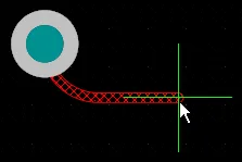
交互式布线一个连接——启动命令并单击一条连接线后,交互式布线器会从该网络对象到当前光标位置寻找路径,并在现有对象之间穿行绕避。单击鼠标按钮将放置所有斜线填充(hatched)的走线段,Ctrl+Click以自动完成布线。
Interactive Routing Tips
-
运行 Route » Interactive Routing 命令(Active Bar 上的  按钮,快捷键:
Ctrl+W),然后单击一个带有网络属性的对象以开始布线。该对象可以是焊盘、连接线、已有过孔、部分已布线网络上的走线端点——事实上,任何属于该网络的对象都可以。
-
PCB 编辑器会跳转到该网络上最近的电气对象(例如焊盘中心或走线段端点),然后尝试从那里到当前光标位置定义一条布线路径。
-
当你开始交互式布线时,PCB 编辑器不仅允许你开始放置走线对象,它还会:
-
监控光标位置和鼠标点击,并应用所有适用的设计规则。
-
跟随你的光标路径,尽量减少放置布线段所需的操作次数。
-
监控连通性,并在你完成布线后立即更新连接线。
-
支持布线专用快捷键,例如按数字键盘上的 * 键切换到下一信号层,或依据过孔样式设计规则插入过孔。
-
布线时,单击以放置直到光标位置的走线,然后继续移动光标,如此循环。这样软件才能准确保持你选择的路径——如果在提交走线前移动得太远,你路径中的某些部分可能会被改变。
-
如果你更喜欢在面板中操作而不是使用快捷键,按 Tab 可暂停布线并打开 Properties 面板中的 Interactive Routing 模式。
-
许多设置(例如当前布线模式、宽度、间距和过孔尺寸)会显示在状态栏或 Heads Up Display 中(Shift+H 用于开/关切换)。
-
交互式布线器能否到达当前光标位置取决于当前的 Routing Conflict Resolution 模式;当 Interactive Routing 命令运行时,该模式会显示在 Status bar( )以及 Heads Up Display 上。
-
按 Shift+R 可在可用的冲突解决模式之间循环切换。你可以在 Interactive Routing 对话框的 页面中配置哪些模式可用。
-
如果模式设置为 Walkaround、 Push and Hug 或 Push,交互式布线器将尝试在现有对象周围及其间隙中寻找路径,如下方视频所示。
-
潜在的布线路径段会以斜线填充显示(下一次点击将放置)或以空心显示(前瞻段;用它来判断上一段应在何处结束)。
-
Click或按 Enter 放置所有斜线填充段。
-
右键单击或按 Esc 终止当前布线。在调用终止之前已提交的布线将被保留。
-
按 Spacebar 切换拐角方向。
-
按 Shift+Spacebar 在可用的拐角模式之间循环切换(了解更多)。
-
按 Backspace “回撤(rip up)”最后放置的线段。如果在放置最后一段时曾pushed推挤过任何对象,它们会被移回原始位置。使用 Auto-Complete 后此功能不可用。
-
切换布线层并插入过孔:
-
当你在通孔焊盘或过孔上单击开始布线后发现自己在错误的层上时,按 L,每按一次都会切换到下一个可用信号层。
-
按数字键盘上的 / 插入过孔并释放该连接(用于扇出)。
-
按 2 插入过孔但不切换层(继续在同一层布线)。
-
Ctrl+Click用于指示交互式布线器尝试自动完成当前布线。如果未能自动完成,并不意味着该连接无法布通;可能是距离太远,或终止点在另一层。
-
Quick Routing 和 Quick Differential Pair Routing 命令提供更轻量的布线方式,设置与能力更少,适用于更简单的设计。
-
本页描述交互式布线单个网络的过程以及控制该过程的设置。如果你在寻找差分对或受控阻抗布线等专用布线技术的信息,请参阅 Routing the PCB 页面上的链接。
-
布线时按 Shift+F1 可显示命令内可用快捷方式菜单。你可以从菜单中选择命令,或使用每个命令旁显示的快捷键。
交互式布线期间的连通性监控
PCB 编辑器包含一个网络分析器(net analyzer),它会持续监控设计空间中所有对象的位置,并在任何网络类型对象被编辑时更新连接线。网络分析器会监控连接到某个网络的所有对象。例如,当一条连接被布通后,两个焊盘之间的连接线会被网络分析器自动移除。如果某个网络仅部分布通,则会在该网络上两个最近的布线点之间显示一条更短的连接线。
即使你选择忽略连接线、从/到不同位置对该网络进行布线也没有关系。一旦布线终止,网络分析器就会运行;如果连接线不再需要,它会将其移除,如下方视频所示。

尽管连接线连接的是焊盘中心,你仍可自由选择从任何位置进行布线。网络分析器会持续监控布线进度并更新连接线。
由于连接线的排列由布线拓扑设计规则决定,因此连接线可能不会连接到走线端点,而是连接到该网络中某个更靠近网络内另一点的位置。如有需要,可在 Preferencesdialog 的 PCB Editing – General 页面启用 Smart Track Ends 选项,以强制连接线连接到走线端点。下方视频演示了这一点。请注意,你可以通过对属于该网络的对象执行一次编辑操作来强制网络分析器运行并更新连接线。编辑操作包括:移动对象、单击并按住对象,或双击以显示该对象的属性。

注意 GND 网络的连接线连接到了焊盘 1,而不是连接到布线末端。启用 Smart Track Ends 并执行一次编辑后,连接线会跳到布线末端。
要了解 PCB 设计空间中的连通性更多内容,请参阅 Understanding Connectivity on Your PCB 页面。
布线在设计空间中的定位方式
PCB 编辑器是基于网格的编辑环境,默认行为是将交互式布线放置在当前捕捉网格(snap grid)上。除捕捉网格外,软件还包含多种额外的捕捉功能,用于帮助你精确定位与对齐设计对象。这些功能合称为 Unified Cursor-Snap System。
该系统的关键要素包括:
-
User-Definable Grids – 同时提供笛卡尔(Cartesian)与极坐标(Polar)格式。
-
Object Snapping– 使已放置的对象能够根据光标与该对象捕捉点(热点)的接近程度,将光标“拉”到相应位置。例如,可用它将光标拉到一个不在网格上的焊盘中心。
-
Snap Guides – 可自由放置,并为对象对齐提供直观的视觉提示。
-
Axis Snapping – 一项在 X 或 Y 方向“拉动”光标的功能,使其在轴向上与附近对象的热点对齐。
光标捕捉功能演示。
捕捉系统(Snap System)选项可在以下位置配置:
了解更多:Working with the Cursor-Snap System
交互式布线基础
当你启动交互式布线命令并单击一条连接线时,交互式布线引擎会从最近的现有网络对象(例如焊盘或已有走线)开始,沿着到当前光标位置的最短可用路径,添加一串相连的走线段。
这些走线段会以斜线填充显示,表示它们是尚未放置的建议走线段(uncommitted)。当你左键单击放置这些走线段后,它们将变为实线。这些实线段称为 soft commits——这表示软件将其识别为你希望保留的线段,但如果你的布线路径使它们变得多余或形成非法形状,交互式布线引擎可能会移除它们,或将其转换回 uncommitted(斜线填充)。此行为在本页第一个视频中有演示。
对一个简单板进行交互式布线。
当你单击连接线开始布线时,软件会跳转到最近的现有网络对象。要更改该网络上被选中的对象:
配置交互式布线器
交互式布线的默认设置可在以下位置配置:
以下可折叠部分包含交互式布线选项与控件的信息:
Net Information

-
Net Name – 正在进行交互式布线的网络名称。
-
Net Class – 正在布线的网络所属的网络类(如果它属于某个网络类)。
-
Length – 总 Signal Length。Signal Length 是对节点到节点总距离的精确计算:会分析已放置对象以解析堆叠或重叠对象、焊盘内的迂回路径,并包含过孔长度。
-
Delay – 所选线段的总延迟(包括未布线的部分)。
在 Properties 面板的 Interactive Routing 模式下,选择可点击链接 Net Name、Net Class、Length 和 Delay,将跳转到 PCB – Nets panel,在其中可查看并更改相关网络的详细信息。
Properties

-
Layer – 使用下拉列表指定布线所在层。
-
Via – 如果过孔关联了模板,则此处显示模板名称。
-
Via Diameter – 指定过孔直径。
-
Via Hole Size – 指定过孔孔径。
-
Width – 使用下拉列表指定线宽。
-
Min – 表示将使用为当前网络定义的设计规则最小线宽
-
Preferred – 表示将使用为当前网络定义的设计规则首选线宽。
-
Max – 表示将使用为当前网络定义的设计规则最大线宽。
Interactive Routing Options

-
Routing Mode – 使用下拉列表或 Shift+R 快捷键循环切换所需的布线模式。可选项如下:
-
Ignore Obstacles – 选择后忽略现有对象(可自由放置走线)。违规会被高亮显示。
-
Walkaround Obstacles – 选择后让交互式布线器绕开现有走线、焊盘和过孔。如果在不产生违规的情况下无法绕开障碍,会出现指示器提示该路径被阻挡。
-
Push Obstacles – 选择后让交互式布线器将现有走线推开让路。该模式也可推动过孔为新布线让路。如果无法在不产生违规的情况下推动障碍,会出现指示器提示该路径被阻挡。
-
HugNPush Obstacles – 选择后让交互式布线器尽可能贴近现有走线、焊盘和过孔,并在必要时推动障碍以继续布线。如果无法在不产生违规的情况下贴近或推动障碍,会出现指示器提示该路径被阻挡。
-
Stop At First Obstacle – 在此模式下,布线引擎会在遇到第一个障碍时停止。
-
AutoRoute Current Layer – 选择后仅在当前层启用自动布线。
-
AutoRoute MultiLayer – 选择后在多层上启用自动布线。
-
Corner Style – 选择所需的拐角样式,或使用 Shift+Spacebar 快捷键循环切换拐角样式。
-
Gloss Effort (Routed) – 直接在面板中选择所需的光顺(gloss)级别,或使用 Shift+Ctrl+G 快捷键在以下选项间循环切换:
-
Off – 在此模式下,光顺基本被禁用。但请注意,布线/拖动后仍会运行清理(cleanup),例如消除重叠的走线段。该模式通常适用于板级布局的后期阶段,需要最高程度的精细调整时(例如手动拖动走线、清理焊盘入口等)。
-
Weak – 在此模式下,应用低级别光顺;交互式布线器仅考虑与你当前正在布线的走线(或正在拖动的走线/过孔)直接相连或位于其附近的走线。该光顺模式通常适用于走线布局的微调或处理关键走线时。
-
Strong – 在此模式下,应用高级别光顺;交互式布线器会寻找最短路径、平滑走线等。该光顺模式通常适用于布局流程的早期阶段,目标是快速完成较大比例的布线。
-
Gloss Effort (Neighbor) – 通过面板在以下选项中选择要应用于“被当前正在布线的网络所推动的走线”的光顺级别:
-
Off – 在此模式下,光顺基本被禁用。但请注意,布线/拖动后仍会运行清理(cleanup),例如消除重叠的走线段。该模式通常适用于板级布局的后期阶段,需要最高程度的精细调整时(例如手动拖动走线、清理焊盘入口等)。
-
Weak – 在此模式下,应用低级别光顺;交互式布线器仅考虑与你当前正在布线的走线(或正在拖动的走线/过孔)直接相连或位于其附近的走线。该光顺模式通常适用于走线布局的微调或处理关键走线时。
-
Strong – 在此模式下,应用高级别光顺;交互式布线器会寻找最短路径、平滑走线等。该光顺模式通常适用于布局流程的早期阶段,目标是快速完成较大比例的布线。
-
Automatically Terminate Routing – 启用后,当你将一条走线完成到目标焊盘时,布线工具不会继续保持在布线模式并 from 该目标焊盘,而是会重置并准备好让你单击下一个源焊盘以开始下一条布线。如果禁用此选项,在你布线到目标焊盘后,工具将保持在布线模式,并将前一个目标焊盘作为下一条布线的源点。
-
Automatically Remove Loops – 启用后会自动移除手动布线过程中产生的任何冗余回路。这使你可以重新布线某个连接,而无需手动删除多余走线。但在某些情况下(例如电源网络)你可能需要回路。你可以对选定网络使用 Shift+D 快捷键切换该选项,以覆盖该网络的全局设置。
-
Remove Loops With Vias – 启用后会自动移除包含过孔的回路。禁用此选项可在回路移除时保留过孔。
-
Remove Net Antennas – 启用此选项可移除任何未连接到其他图元、并形成“天线”的走线或圆弧端点。
-
Allow Via Pushing – 勾选此选项可在 Push Obstacles 或 HugNPush Obstacles 模式下允许推动过孔。
-
Pin Swapping – 勾选此选项以启用引脚互换,或使用 Shift+C 快捷键。
-
Auto Shrinking – 勾选此选项可自动将布线宽度收缩到一个允许布线的值,以便在当前所选线宽无法在障碍之间通过的区域完成布线。了解更多:Routing Auto-shrinking。
-
Display Clearance Boundaries– 启用后,会在本地查看圆内,将由现有对象及适用的间距规则定义的禁布(no-go)间距区域以阴影多边形显示;或在布线过程中使用 Ctrl+W 快捷键切换开/关。此选项在 Ignore Obstacles 布线模式下不可用。
-
Reduce Clearance Display Area – 启用后使用更小的间距边界。仅当 Display Clearance Boundaries option 启用时此选项才可用。
-
Show Length Gauge – 启用后显示长度量规,用于显示当前已布线长度。量规设置由适用设计规则中定义的一组约束计算得出。布线过程中使用 Shift+G 快捷键切换显示开/关。
-
Pad Entry Stability – 保护居中焊盘进入(centered pad entries)。使用滑块配置保护级别:
-
Apply Trace Centering – 启用走线居中(trace centering)功能。启用后,在可能的情况下,会在正在布线的网络与现有焊盘/过孔之间增加额外间距,并提供以下选项用于配置该功能:
了解更多:Trace Centering。
-
Miter Ratio – 控制最小拐角紧致度。Miter Ratio(斜接比)乘以当前线宽,等于在该比值下可布出的最紧 U 形的两侧壁间距。输入一个大于或等于 0 的正值(会自动加上 x 倍数)。了解更多:Mitered Corners。
-
Subnet Jumper Length – 指定交互式布线期间放置的子网跳线(subnet jumper)的期望长度 – 了解更多。
Rules

适用设计规则所定义的约束将列在 Properties 面板的 Rules 区域下。
-
Via Constraint – 单击打开 Edit PCB Rule 对话框,可在其中为过孔定义 PCB 规则。
-
Width Constraint – 单击打开 Edit PCB Rule 对话框,可在其中为布线宽度定义 PCB 规则。
控制拐角样式
在交互式布线期间,由走线与圆弧形成的拐角形状称为 corner style。斜角拐角最常见,但使用圆弧放置的圆角拐角也很受欢迎。共有 5 种可用拐角样式,其中 4 种还包含拐角方向子模式。
-
布线时按 Shift+Spacebar 可在拐角样式间循环切换,当前样式会显示在 Status bar(  )以及 Heads Up display 中。
-
按 Spacebar 可切换拐角方向。
-
或者,按 Tab 打开 Properties 面板的 Interactive Routing 模式,并在其中更改拐角样式。
-
按 1 快捷键可在“带前瞻段(look-ahead segment)布线”和“单击时放置所有可见线段”之间切换。在前瞻模式下,最后一段会以空心显示。该段称为前瞻段,单击时不会放置它。它可让你在不提交放置最后一段的情况下,先确定前一段应终止的位置。
-
按 Backspace 键移除最后一个顶点。
| 拐角样式 |
初始拐角方向 |
备用拐角方向 |
备注 |
| Track 45 |
 |
 |
|
| Line 45/90 With Arc |
 |
 |
使用 , 与 . 键可交互式更改圆弧半径,按住 Shift 可加速半径变化。 |
| Track 90 |
 |
 |
|
| Line 90/90 Vertical Start With Arc |
 |
 |
使用 , 与 . 键可交互式更改圆弧半径,按住 Shift 可加速半径变化。 |
| Any Angle |
 |
|
将此模式与 Strong Glossing 配合使用可进行蛇形布线(snake routing)。
|
斜接或圆角拐角
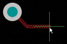
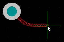
拐角可以用短的直线走线段来定义,也可以用一个或多个圆弧来创建。下图展示了两种最常用的拐角样式:Track 45 与 Any Angle。

 两种拐角样式示例:Track 45 与 Any Angle,单击可放大图片。
注意第一张图中,交互式布线器在保持整体正交/对角的布线走向模式。在 Any Angle 样式下,交互式布线器会在起点位置与光标位置之间寻找最短路径——这种布线方式称为 Snake Routing。
斜接拐角
最常见的布线拐角形状是 45 度斜接(对角)拐角。切换到 Track 45 拐角模式以布设对角拐角。为确保布线过程中不会无意创建直角或锐角拐角,交互式布线与交互式滑动都包含 Miter Ratio 选项。输入一个大于或等于 0 的正值。下方展示了同一条走线在不同 Miter Ratio 取值下的示例。
❯ ❮
Javascript ID: InteractiveRouting_MiterRation_AD24_5
|
Miter Ratio 乘以当前线宽,等于在该斜接比下可布出的最紧 U 形的两侧壁间距,如下所示。

将 Miter Ratio 设为 0,可在布线或拖动走线时创建直角或锐角拐角。在这种情况下,不会创建斜接(也就是所谓真正的零斜接)——查看示例。此功能处于 Open Beta 状态,并且在 Advanced Settings dialog 中启用 PCB.ZeroMitersRemoving 选项时可用。当该选项禁用时,若 Miter Ratio = 0,会创建一个被相邻走线完全覆盖的短斜接。
-
Miter Ratio 面板中定义的 Properties 值会在交互式布线、交互式滑动、光顺(glossing)与重走线(retracing)期间使用。
-
交互式布线与滑动使用的默认 Miter Ratio 值在 Preferences 对话框的 PCB Editor – Interactive Routing 页面中配置。
-
光顺与重走线使用的默认 Miter Ratio 值在 Preferences 对话框的 PCB Editor – Gloss and Retrace 页面中配置。
拐角中的圆弧
许多设计人员需要圆角拐角。圆角拐角可通过 Line 45/90 With Arc 拐角模式或 Line 90/90 With Arc 拐角模式进行布设。Line 90/90 With Arc 拐角模式会强制 90 度拐角,因此如果走线需要以 45 度继续,请使用 Line 45/90 With Arc 拐角模式。布线过程中可使用  与
与  键交互式调整圆弧大小(按住 Shift 可加速调整过程)。
在交互式布线中选择圆角拐角样式时,光顺引擎会倾向于沿现有弯曲对象周围的切向路径。也就是说,用于创建拐角的圆弧会被定位并按半径精确调整,以恰好绕过现有对象。这旨在在大量曲线形状中形成平滑布线,例如 BGA 下方的逃逸过孔(escape via)图案。如果 Routing Gloss Effort 设为 Strong,可能会导致圆弧之间的直线走线段以非水平或非垂直的角度放置。
如果你要求所有直线走线段都严格水平或垂直,同时拐角为圆角,那么更高效的方法可能是先用对角拐角进行布线,然后对布线进行光顺以将拐角圆角化。可通过将 Hugging Style 设为 Rounded,然后运行 Retrace Selected 命令来实现。这里使用 Retrace 而不是 Gloss Selected,因为 Retrace 不会尝试缩短路径并减少拐角数量,而是会依据 current design rule settings 沿相同路径进行光顺处理。下文将讨论光顺。
对现有布线的拐角进行圆角化。
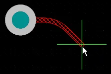
蛇形布线
除了使用前面讨论的圆弧拐角模式外,还可以通过将拐角样式设为 Any Angle,并将 Routing Gloss Effort 设为 Strong 来实现一种平滑流动的点到点布线风格。这会生成所谓的 Snake Routing。当布线需要任意角度走线穿过多个弯曲对象时使用,如下方示例视频所示。
蛇形布线,拐角样式设为 Any Angle。
自动完成连接
交互式布线器能够尝试将连接自动完成(Auto-Complete)到目标焊盘。按住 Ctrl 和 Left Click 可指示交互式布线器尝试完成当前连接。与逐段放置走线段相比,这可以让布线快得多;不过,Auto-Complete 功能也有一些限制,如下所示:
-
起点与目标焊盘必须位于同一层。
-
走线必须能够按照设计规则完成(前提是未忽略布线冲突)。
Auto-Complete 可在任何时候使用,你甚至可以直接在焊盘或连接线上 Ctrl+click 来对其进行布线,无需先选中它。你也可以对已部分布线的连接使用 Auto-Complete。为此,在最后一段走线的末端或剩余的连接线上 Ctrl+click,即可将其补全到目标端。
如果某条连接无法自动完成,工具将返回到上一次使用的交互式布线模式。
子网跳线
基于 FPGA 的设计的一大优势在于:布线挑战既可以在 PCB 上解决,也可以在 FPGA 内部解决,从而有可能减少布线层数并简化 PCB。要实现这一点,设计系统必须同时支持由 PCB 驱动和由 FPGA 驱动的引脚互换。Altium Designer 支持在 PCB 编辑器中进行引脚互换,从简单的 2 引脚器件一直到高引脚数的 FPGA。
为支持在设计流程的任何阶段(包括在已布线的 PCB 上)进行引脚互换,PCB 编辑器可以添加和移除一种小型布线连接器,称为 subnet jumpers。子网跳线是一小段走线,软件会将其识别为一种可轻松放置与移除的元素;你可以通过 Route 菜单中的 Add 和 Remove Subnet Jumper 命令手动操作,或者在交互式布线过程中当你布线到可互换引脚时,由布线引擎自动添加。
❯ ❮
Javascript ID: SubnetJumpers
|
|
|
手动放置的子网跳线
当网络中仍包含一小段连接线时,可以运行 Route » Add Subnet Jumpers 命令来完成布线。执行该命令后,会出现 Subnet Connector 对话框,如下所示。在对话框中输入一个数值并点击 Run 按钮后,板上的每一条连接线都会被检查,凡长度不超过 Maximum Subnet Separation 的连接线都会被替换为一段走线。该走线段的线宽将与被连接的两段走线中较窄者相同。请注意,子网跳线放置的角度由连接线端点的位置决定。
 指定子网跳线允许的最大长度。
交互式布线过程中放置的子网跳线
如果正在布线的网络被配置为可互换,布线引擎将识别并高亮所有潜在的布线目标。如果你正朝向一段现有走线段(而不是焊盘)进行布线,并且你选择布线到可互换的走线段而不是同网络的走线段,则交互式布线引擎会自动添加一个子网跳线,如下方视频所示。
在交互式布线过程中,如果目标是可互换的走线路径而不是同网络路径,则会自动添加子网跳线。
将子网跳线解析为标准走线
要将子网跳线转换为普通走线段,在其上点击并短暂按住,然后松开鼠标按钮(不要移动鼠标)。子网跳线将被替换为标准走线段,如上方视频末尾所示。若要用同样的方法一次性转换多个子网跳线,请先选中这些子网跳线,然后在其中一个已选子网跳线上点击并按住。要选中板上所有子网跳线,请在 PCB Filter 面板中运行查询 IsSubnetJumper,并启用 Select 复选框。
交互式布线与交互式滑动选项
无论你是在交互式布线一条连接,还是拖动现有走线为更多布线腾出空间,都会应用同一套布线技术。本节汇总了 Properties 面板的 Interactive Routing 与 Interactive Sliding 模式中可用的选项。其中许多选项的默认设置在 Preferences 对话框的 PCB Editor – Interactive Routing 页面中配置。
Interactive Routing and Interactive Sliding Options
Gloss Effort (Routed)
在交互式布线、交互式滑动或 ActiveRouting 等布线事件期间,软件会运行光顺(glossing)引擎。光顺引擎会持续检查当前布线事件中放置或受影响的所有线段,尝试提升结果质量。质量衡量包括:减少拐角数量、减少线段数量、消除锐角以及缩短总体走线长度。
光顺有三种设置:Off、Weak 和 Strong。这些设置在 Glossing – Smoothing the Routes 小节中讨论。
Gloss Effort (Neighbor)
Gloss Effort (Neighbor) 用于配置对受当前交互式布线或滑动影响的相邻走线所应用的光顺程度。同样有三种设置:Off、Weak 和 Strong。
贴靠样式(Hugging Style)
该选项控制交互式滑动期间拐角形状的处理方式,并会同时影响被滑动的走线与被推挤的走线。滑动时使用 Shift+Spacebar 快捷键在三种模式间循环切换。
-
45 Degree – 滑动时始终使用直线的正交/对角线线段来形成拐角(用于传统的正交/对角布线行为)。
-
Mixed – 当被移动/推挤的对象为直线时使用直线走线段;当对象为曲线时使用圆弧。
-
Rounded – 在涉及移动/推挤的每个顶点处使用圆弧。该模式用于蛇形布线,以及在光顺时(交互式布线与手动光顺)使用“圆弧 + 任意角度”走线。
在交互式滑动过程中,受走线移动影响的现有拐角将根据当前贴靠样式进行转换(45 度转圆角,或圆角转 45 度)。
冲突解决(Conflict Resolution)
该选项决定当布线/滑动对象遇到现有对象时应如何响应。布线或滑动时使用 Shift+R 快捷键在可用模式间循环切换。
这些模式在 Preferences 对话框的 PCB Editor – Interactive Routing 页面中被称为 Routing Conflict Resolution modes。
顶点动作(Vertex Action)
为更好地支持设计人员轻松操控并重塑现有布线,当你点击并拖动的是顶点而不是走线或圆弧时(顶点是两段线段相接的拐角位置),会应用特定选项。滑动时使用 Spacebar 快捷键在可用模式间循环切换。
-
Deform – 断开或加长与移动顶点相连的走线段,使顶点跟随光标移动。
-
Scale – 保持拐角形状,缩放并移动进入拐角的走线段,使顶点保持附着在光标上。
-
Smooth – 平滑重塑拐角:向内拖动时(在 Mixed 或 Rounded 贴靠样式下)插入圆弧以形成曲线拐角,并对滑动过程中受影响的每个顶点执行;在 Rounded 贴靠样式下向外拖动时也会添加圆弧。
复选框选项
-
Automatically Terminate Routing – 当当前正在布线的连接到达目标焊盘时,自动停止该网络的布线,但仍保持在 Interactive Routing 命令中,随时准备开始布线另一条网络。
-
Automatically Remove Loops – 启用后,你可以为现有走线布出一条新路径——当新路径回到并与现有路径相接时,多余的环路会被自动移除。了解更多:Modifying Existing Routes。
-
Remove Net Antennas – 网络天线(net antenna)是一段短的、未端接的走线(圆弧)段。如果当前布线影响到天线所接触的对象,这些天线会被自动移除。
-
Allow Via Pushing – 在 Push 或 Hug & Push 模式下布线/滑动时,允许现有过孔也被推挤移动。
-
Display Clearance Boundaries – 显示现有对象周围的禁布区(no-go area),该区域由适用的间距(Clearance)设计规则定义。
-
Reduce Clearance Display Area – 将该显示缩减为当前光标位置周围的圆形区域。
-
Show Length Gauge – 长度量规(length gauge)指示当前走线满足适用的长度(Length)与匹配长度(Matched Length)设计规则的程度。了解更多:Length Tuning。
焊盘进入稳定性(Pad Entry Stability)
Pad Entry Stability 滑块用于保护居中的焊盘进入,防止光顺将已居中的走线偏离中心(它会保持已居中的走线仍在中心,但不会把未居中的走线自动居中)。使用滑块条配置保护级别:
走线居中(Trace Centering)
当启用 Apply Trace Centering 选项时,走线居中(Trace Centering)功能会在可能的情况下,在正在布线或拖动的网络与现有焊盘/过孔之间增加额外的间距(clearance)。启用该选项后,可使用以下选项来配置此功能:
要在交互式滑动走线时禁用走线居中,你可以在 Preferences 对话框的 PCB Editor – Interactive Routing 页面中的 Dragging 区域使用 Disable Trace Centering When Dragging 选项,或在用于交互式滑动的 Properties 面板的 Properties 区域中使用该选项。启用此选项后,即使该功能的主 Apply Trace Centering 选项已启用,走线居中也不会在交互式滑动走线期间生效。
了解更多关于 Trace Centering。
Miter Ratio
Miter Ratio 控制最小拐角紧致度。Miter Ratio 乘以当前线宽,等于在该比率下可布出的最紧 U 形的两侧壁间距,如本页前面 Mitered Corners 的说明所示。输入一个大于或等于零的正值(x 倍数会自动添加)。
Min Arc Ratio
Min Arc Ratio 会在任意角度交互式布线期间应用,也会在使用 Mixed Hugging Style 的交互式滑动期间应用。该比率用于确定允许的最小圆弧半径;当圆弧半径低于该最小值时,圆弧会被线段替代,其中:
Min Arc Radius = Min Arc Ratio x Arc Width
-
该设置不会在“拐角圆弧(arc in corner)”布线或使用 Rounded Hugging Style 的交互式滑动期间应用,因为这些模式不使用分段圆弧。
-
将 Minimum Arc Ratio 设为 0(零)以始终使用圆弧。
了解更多关于 Modifying Existing Routes
Glossing – Smoothing the Routes
为帮助生成拐角数量最少且更整洁的布线,PCB 编辑器包含一个 Glossing 工具。Glossing 是一套专门开发的复杂算法,用于生成更干净的布线与焊盘引出,并遵循适用设计规则的意图。Glossing 会尝试缩短路径长度、改善拐角形状并减少拐角数量,通常可得到由更少线段构成的更整洁布线。Glossing 也会保持子网跳线(sub-net jumpers)不变;当存在基于房间(room-based)的线宽规则时,也会遵循边界处的线宽变化。当你移动光标并定义新的交互式布线路径时,所有尚未提交的布线也会自动进行 gloss。
Glossing 引擎还包含一个 Retrace Selected 命令。当你需要将所选布线更新为你在布线规则设置中所做的更改时使用该命令。通过 Retrace,你可以将所选电源走线“加粗”,或将所选差分对更新为新的线宽与间距设置。
Glossing 会在以下情况下应用:交互式布线(Interactive Routing)、交互式滑动(Interactive Sliding),以及运行 Gloss Selected 或 Retrace Selected 命令时。
Glossing 有三种设置:Off、Weak 和 Strong。在交互式布线或交互式滑动期间,使用 Ctrl+Shift+G 快捷键在这些设置间循环,或按 Tab 打开 Properties 面板并选择设置:
-
Off – 在此模式下,glossing 基本被禁用。但请注意,布线/拖动完成后仍会运行清理(cleanup),例如消除重叠的走线段。该模式通常适用于板级布局的收尾阶段,需要最高程度的精细调整时(例如手动拖动走线、清理焊盘引出等)。
-
Weak – 在此模式下,会应用较低程度的 glossing;交互式布线器只会考虑与你当前正在布线的走线直接相连或位于其附近的走线(或正在拖动的走线/过孔)。换言之,走线几何形状主要被保留,只做局部平滑。该模式通常适用于微调走线布局或处理关键走线。
-
Strong – 在此模式下,会应用较高程度的 glossing;交互式布线器会寻找最短路径、平滑走线等。该模式通常适用于布局流程的早期阶段,目标是快速完成较大部分的布线。注意:当 Strong glossing 与某种拐角圆弧模式结合时,也允许任意角度走线。这里的假设是:既然设计者在对拐角进行圆弧化,他们也会接受拐角之间的非正交布线。
除当前的 Gloss Effort 设置外,Glossing 也遵循以下设置:
-
Corner Style
-
Hugging Style(在交互式滑动期间,以及运行 Gloss Selected 或 Retrace Selected 命令时)
-
Miter Ratio
-
Min Arc Ratio
通过这些选项,Glossing 控制拐角生成的紧致程度,以及在绕过弧形障碍物时走线的曲线形状如何形成。
要在交互式布线或滑动期间控制 glossing 强度,有两个选项:Gloss Effort (Routed) 用于正在放置或拖动的走线,Gloss Effort (Neighbor) 用于受当前交互式布线或滑动影响的相邻走线。下面展示了这些选项在不同 gloss effort 模式下的示例。
❯ ❮
Javascript ID: InteractiveRouting_GlossEffortRouted_AD24
|
❯ ❮
Javascript ID: InteractiveRouting_GlossEffortNeighbor_AD24
|
可以通过运行 Route » Gloss Selected 命令对现有布线进行 gloss。你可以利用这一点来执行设计更改,例如在运行该命令前配置 Corner Style,以将斜切拐角(mitered corners)转换为圆弧。
了解更多关于 Glossing & Retracing of Existing Routes
Temporarily Inhibit Glossing – Glossing 是交互式布线与滑动的核心功能,但在某些情况下它会阻止你获得期望的走线形状。在布线期间按住 Ctrl+Shift 快捷键可临时抑制 glossing;松开后,glossing 将按当前设置重新启用。
执行 Gloss
glossing 工具运行于:
-
During Interactive Routing – 按照当前 gloss 设置执行,这些设置定义在 Preferences 对话框的 PCB Editor – Interactive Routing 页面,或 Properties 面板的 Interactive Routing mode 中。
-
During Interactive Sliding – 按照当前 gloss 设置执行,这些设置定义在 Preferences 对话框的 PCB Editor – Interactive Routing 页面,或 Properties 面板的 Interactive Sliding mode 中。
-
对当前选中的布线 – 从菜单中选择 Route » Gloss Selected 命令或按 Ctrl+Alt+G 键盘快捷键,以按照 Preferences 对话框的 PCB Editor – Gloss and Retrace 页面或 Gloss And Retrace 面板 中定义的 gloss 设置进行 gloss。
-
After ActiveRoute – 通过在 PCB ActiveRoute 面板 中启用 Gloss Results 选项。
Inhibit Glossing During Routing and Sliding
有时你可能希望临时关闭 glossing。按住 Ctrl+Shift 快捷键即可抑制 glossing——一旦松开按键,glossing 会按当前 Routing Gloss Effort 设置恢复。注意:状态栏不会反映该状态;它会继续显示上一次选择的状态。
Glossing Options
Gloss Effort (Routed)
走线被 gloss 的强度由当前 Gloss Effort (Routed) 设置控制。在 Preferences 对话框的 Interactive Routing 页面中配置该选项,或使用 Ctrl+Shift+G 快捷键在三种模式间循环。当前设置会显示在状态栏中。(show image )
)
-
Off – 在此模式下,glossing 基本被禁用。但请注意,布线/拖动完成后仍会运行清理(cleanup),例如消除重叠的走线段。该模式通常适用于板级布局的收尾阶段,需要最高程度的精细调整时(例如手动拖动走线、清理焊盘引出等)。
-
Weak – 在此模式下,会应用较低程度的 glossing;交互式布线器只会考虑与你当前正在布线的走线直接相连或位于其附近的走线(或正在拖动的走线/过孔)。该模式通常适用于微调走线布局或处理关键走线。
-
Strong – 在此模式下,会应用较高程度的 glossing,并强烈强调最短路径。该模式通常适用于布局流程的早期阶段,目标是快速完成板上较大部分的布线。
Gloss Effort (Neighbor)
Gloss Effort (Neighbor) 用于配置对受当前交互式布线或滑动影响的相邻走线所应用的 glossing 量。它同样有三种设置:Off、Weak 和 Strong。
Hugging Style
此选项用于控制在光顺(Glossing)过程中如何处理拐角形状。光顺会应用于所有受当前编辑操作影响的走线段,因此也可能影响周围走线。例如,在推挤模式下进行交互式布线或交互式滑动时,被滑动的走线以及被推挤的走线都会根据当前的 Hugging Style 设置进行光顺处理。
-
45 Degree – 始终使用直线的正交/对角线线段来生成拐角(此模式用于传统的正交/对角线布线行为)。
-
Mixed – 当被移动/被推挤的对象是直线时使用直线走线段;当它们是曲线时使用圆弧。
-
Rounded – 在每个被光顺的顶点处使用圆弧。此模式用于蛇形布线,并用于在光顺时(交互式布线与手动光顺期间)使用“圆弧 + 任意角度”走线。
Minimum Arc Ratio
Minimum Arc Ratio(最小圆弧比)适用于任意角度交互式布线,以及在 Mixed Hugging Style 下的交互式滑动。该比值用于确定允许的最小圆弧半径;当圆弧半径小于该最小值时,圆弧将被走线段替代,其中:
Min Arc Radius = Min Arc Ratio x Arc Width
-
此设置不适用于“拐角布线中的任何圆弧”,也不适用于在 Rounded Hugging Style 下的交互式滑动,因为这些模式不使用分段圆弧。
-
将 Minimum Arc Ratio 设为 0(零)可始终使用圆弧。
Miter Ratio
Miter Ratio(斜接比)用于控制拐角的最小紧凑程度。Miter Ratio 乘以当前走线宽度,等于在该比值下可布出的最紧 U 形的两侧壁间距。了解更多 Mitered Corners。
Pad Entry Stability
Pad Entry Stability 滑块用于保护居中的焊盘进线。它在光顺期间用于保护已经居中的焊盘进入(退出)位置;不会尝试将现有的偏心焊盘进线重新居中。
-
0 (Off) = 无保护
-
10 (Max) = 最大保护
Pad Entry Stability 功能演示。
换句话说,此选项用于告知光顺引擎:布线拐角必须离焊盘边缘多近,才允许将焊盘进线位置横向偏移。
在布线过程中控制走线宽度与过孔尺寸
当你运行交互式布线命令并单击开始布线时,会从最近的焊盘到当前光标位置创建一系列走线对象。这些走线的宽度由当前 Track Width Mode 设置决定,并会在布线时显示在状态栏上(如下方视频所示)。
Routing Width Source(走线宽度来源)共有四种可能的设置:
User Choice / Min rule / Preferred rule / Max rule 的选择会被保存,并可在 Preferences 对话框的 PCB Editor – Interactive Routing 页面中,通过 the Track Width Mode drop-down 进行选择。
布线时切换 Track Width Mode
在交互式布线过程中,你可以按下 3 快捷键在四种走线宽度选项间循环切换,如下方视频所示。当前模式会显示在状态栏上。如果你忘记了命令内快捷键,可在运行命令时按 Shift+F1 显示列表。
要在布线时更改走线宽度来源,请按键盘上的 3 键。按 Shift+W 可为 User Width 选择不同的值。
当你更改 Track Width Mode 时,会在适用设计规则中定义的数值(Min/Preferred/Max)与 User Choice 之间切换。
如果选择 User Choice,则走线宽度将为:
布线时更改 User Choice 走线宽度
要在布线时更改宽度,可使用以下快捷方式。注意:如果 Interactive Routing Width Sources 选项被设置为某个基于规则的宽度选项,那么一旦使用这些快捷方式中的任意一个,该选项会被更改为 User Choice。
-
Shift+W – 在布线过程中使用此快捷方式打开 Choose Width 对话框。单击新的宽度即可关闭对话框,并以所选宽度继续布线。可用宽度可在 Favorite Interactive Routing Widths dialog 中编辑:通过在 Preferences 对话框的 PCB Editor – Interactive Routing 页面点击 Favorite Interactive Routing Widths 按钮进入,或在 PCB 编辑器设计空间中使用 O 键盘快捷键,然后在弹出菜单中选择 Favorite Routing Widths 条目进入。
-
Tab – 若所需宽度未定义为常用值,可使用此快捷方式。按下 Tab 将 open the Properties panel in Interactive Routing mode。当前编辑会话将暂停,并且面板会打开并选中当前 Width。输入新的宽度值后按 Enter 以新宽度继续布线。或者,在输入新宽度值后,单击暂停按钮叠层以恢复布线。若不修改数值而恢复布线,请按 Esc。
请记住:如果你在布线过程中使用上述任一方法更改宽度,Track Width Mode 会自动切换为 User Choice。
布线走线宽度必须介于适用的 Routing Width 设计规则所指定的最小值与最大值之间。如果你尝试将宽度更改为超出规则 Minimum 与 Maximum 设置范围的值,软件会自动将其裁剪回 Min-Max 范围内。
布线时切换层
在布线过程中交互式切换层有两种方法:
-
按数字小键盘上的 * 键。每按一次都会切换到下一个可用的信号层(向下)。
-
使用 Ctrl+Shift+Wheel Scroll 快捷键组合。按住 Ctrl+Shift 键,然后向前滚动鼠标滚轮可使 down 在可用信号层间切换;向后滚动鼠标滚轮可使 up 在可用信号层间切换。注意:该快捷方式可在任何时候用于切换层。如果当前未在布线,此快捷键组合会在所有已启用层之间逐层切换。
系统会在最后一个拐角(即最后两段线段相接处)自动添加过孔。与走线宽度类似,过孔尺寸由当前 Via Size Mode 决定,如下方视频所示。该模式可在 Interactive Routing Width Sources 选项中预先配置。
使用 Ctrl+Shift+Scroll 快捷方式切换层,并使用 4 快捷键在过孔尺寸选项间循环切换。
布线时切换 Via Size Mode
与走线宽度类似,在交互式布线期间选择过孔尺寸也有四种可能选项:
在交互式布线过程中按 4 快捷键即可在四种过孔尺寸选项间循环切换。当前模式会显示在状态栏上,如上方视频所示。
布线时更改 User Choice 过孔尺寸
要在布线时更改 User Choice 过孔尺寸:
-
Shift+V – 在交互式布线过程中按此快捷方式打开 Choose Via Size 对话框。该对话框会自动列出当前设计中使用的所有过孔尺寸。选择一个过孔尺寸后点击 OK,将其设为 User Choice 过孔尺寸。

-
Tab – 除了在布线时更改走线宽度外,当你按 Tab 以在 Interactive Routing 模式下打开 Properties 面板时,也可以更改 Via Diameter。与走线宽度一样,你输入的尺寸必须介于适用的 Routing Via Style 设计规则定义的最小值与最大值之间。
布线时更改 Via Type
如果定义了多个 Via Type,那么在切换层时,对于所跨越的层可能会有多个可用的 Via Type。例如:Top 与 Mid1 之间可使用盲孔,同时也存在 Top-Bottom 的 Via Type。如果你正在进行层切换且有多个 Via Type 可用,可按 6 快捷键在可能的 Via Type 选项间循环切换(或按 8 快捷键显示列表)。更详细信息请参阅 Defining the Via Types 页面。此外,最后一次使用的过孔叠层会作为下一条网络布线的默认值保留。默认过孔叠层仅在当前编辑会话中保留。

在从 L1 切换到 L4 的层变更过程中放置堆叠 µVia。Interactive Routing 模式的 Properties panel 会显示将要放置的过孔类型。按 6 可在可能的过孔堆叠之间循环切换;按 8 可显示可能的过孔堆叠列表。
使用 Look Ahead Routing Segment 时的过孔行为
在交互式布线过程中,尚未放置的走线段会以斜线阴影显示,已提交的走线段为实线。还有另一种模式:与光标相连的最后一段会以空心(轮廓)显示,这一段称为 Look Ahead 段。当你在 Look Ahead 模式下布线时,点击会放置所有带阴影的线段,但不会放置空心线段。其思路是:你可以利用 Look Ahead 段在不提交最后一段的情况下,精确放置前一段(或多段)。在布线时按 1 快捷键可切换 Look Ahead 模式的开/关。
如果你在层变更期间开启 Look Ahead 模式,由于点击时不会放置 Look Ahead 段,过孔会从光标位置跳回到前一个拐角。下面的视频演示了该行为。
 如果你在层变更期间按 1 来切换 Look Ahead 模式的开/关,过孔会跳回到上一段“已准备放置”的线段末端。
控制 SMD 焊盘进线
SMD To Corner 和 SMD Entry 设计规则会影响布线过程。你需要在开始布线之前设置好必要的设计规则,以便控制走线如何进入和离开 SMD 焊盘。打开 PCB Rules and Constraints Editor dialog(从主菜单点击 Design » Rules)来创建并配置这些设计规则。

在 SMD to Corner 设计规则中,“到拐角距离”的数值应大于走线宽度或适用的间距规则(两者取较大者)。如果必须小于该值,你可以用以下三种方式处理:
-
在进行焊盘进线时按住 Spacebar 。这有助于将最后一段走线沿焊盘中心对齐。
-
先在靠近焊盘处提交布线,然后在不进行 glossing 的情况下完成焊盘进线(按住 Ctrl+Shift 可临时禁用 glossing)。
-
如果焊盘进线存在多个可能的入口,将鼠标移到焊盘内部。这样你就可以选择希望的 SMD 进线位置。
对于 SMD Entry 规则,焊盘的 Side 指较长的边。设计规则中的 Side 选项仅在焊盘 SideLength > 2 * EndLength 时才会应用。这样做是因为大多数 SMD 分立器件的焊盘几乎是正方形,对于这些器件,通常希望可以从焊盘的任意边进线。
走线居中(Trace Centering)
许多设计人员的常见需求是:当走线在焊盘或过孔之间通过时,尽可能让走线居中。当前布线引擎的行为是按设计规则中定义的最小允许间距来放置走线段,把在焊盘之间“拉开/居中”的任务留给设计人员。
走线居中功能通过在正在布线或拖动的网络与现有焊盘/过孔之间增加额外间距,来帮助完成居中过程。布线引擎理解这部分额外间距是“期望的”而非“强制的”,因此在需要时可以回收其中一部分或全部,例如在现有焊盘/过孔之间再挤入第二条或第三条走线时。如果布线引擎必须回收部分间距,它会从走线两侧同时回收,以便在可能的情况下仍保持居中。
走线居中行为可通过 Preferences dialog 的 PCB Editor – Interactive Routing page 上的选项,以及交互式布线期间 Properties panel 中的选项进行配置。

Preferences dialog 中用于交互式布线的走线居中选项

Properties panel 中用于交互式布线的走线居中选项
可在焊盘和过孔周围增加额外间距,以使走线居中。
-
该功能在所有布线模式下都可用,包括 Any Angle。在 interactive differential pair routing 和 interactive sliding 期间也可用。
-
要在交互式滑动走线时禁用走线居中,可使用 Preferences dialog 的 PCB Editor – Interactive Routing page 中 Dragging 区域的 Disable Trace Centering When Dragging 选项,或用于交互式滑动的 Properties panel 中 Properties 区域的对应选项。启用该选项后,即使该功能的主 Apply Trace Centering 选项已启用,交互式滑动走线时也不会应用走线居中。
布线自动缩宽(Routing Auto-shrinking)
当使用交互式布线器布线时,如果以当前选择的布线宽度无法在障碍物之间通过,自动缩宽功能允许自动将线宽缩小到一个能够在该位置完成布线的数值(前提是缩小后的走线不会违反相应约束中允许的最小线宽)。在 Preferences dialog 的 PCB Editor – Interactive Routing page 上启用 Auto Shrinking 选项,并在 interactive routing 期间通过 Properties panel 启用该功能。
在布线过程中自动改变布线宽度
现代器件技术的一个常见挑战是:同一网络在跨板布线时需要使用不同的线宽。例如,进入或离开 BGA 时通常需要更窄的扇出走线,在 BGA 封装边缘再切换回首选线宽。
这可以在交互式布线时通过本页前面介绍的技巧手动实现。你也可以通过添加一个 placement room 以及基于 room 的布线宽度规则来自动化这种宽度切换行为。完成后,走线会在进入或离开 room 时自动变细(neck)或变宽(expand)。
该功能的工作方式是:
完成后,如下方视频所示,当你布线进入或离开 placement room 时,线宽会自动变化。


会遵循宽度规则,并在跨越 room 边界时智能调整走线段尺寸。
基于 room 的布线需要先定义 placement room。placement room 也是一条设计规则。虽然你可以先创建规则再在设计规则对话框中定义 room,但更高效的方式通常是反过来:交互式创建 room;Altium Designer 会为你创建相应的设计规则。
创建 Room 规则
Design » Rooms 子菜单包含多种 room 定义命令。
 Room 是一个很有用的功能,可用于控制元件放置位置,也可用于控制在电路板该区域内应用哪些规则。
围绕所选元件创建的 room 会产生以下结果:
-
会创建一个由所选元件组成的 Component Class。检查该类(Design » Classes),并按需更新 Component Class Name。
-
会创建一条 Placement Room Definition 设计规则。该规则的作用域会指向步骤 1 中创建的 Component Class。如果你更改了 Component Class 名称,则必须更新规则作用域(Full Query)以匹配。
-
Placement Room Definition 设计规则也会被自动命名。按需更新名称,并记下该名称,因为在其他设计规则中会通过其 Name 来引用该 room。
- 如果需要,可调整房间(Room)的大小。操作方法是:单击一次选中它,然后在某个顶点上单击并按住,拖动以移动角点或边。单击顶点并开始移动后,也可以按 Shift 执行对称缩放。
,而不是某个元件类。") 在本示例中,该规则的作用范围被限定为针对特定的 BGA 封装(“BGA50P18X18-180”),而不是某个元件类。
在本示例中,该规则的作用范围被限定为针对特定的 BGA 封装(“BGA50P18X18-180”),而不是某个元件类。
Placement Room Definition(放置房间定义)设计规则通常会限定为针对一个或多个元件。在这种情况下,它最终是用来控制房间所定义区域内的布线,因此实际上不必将其限定为针对特定元件。例如,规则的作用范围(Full Query)可以设置为 All,布线仍会按要求工作。将其限定为针对房间内的元件的好处是:如果需要移动该元件(或这些元件),可以使用 Design » Rooms » Move Room 命令将房间与元件一起移动。
创建基于房间的布线规则
定义好需要不同布线宽度的房间区域后,就可以创建布线宽度规则。下图展示了一个 Routing Width(布线宽度)规则示例:该规则被限定为当布线触及名为 Room_BGA 的房间时,将布线宽度设置为 0.075mm。Altium Designer 的交互式布线引擎会在房间边界处自动终止当前走线段,并开始一段新的走线段,以满足此类规则要求。

一个 Routing Width 设计规则:限定在 Room_BGA 房间内将所有网络的线宽设置为 0.075mm。注意该规则在规则树中排在最前,表示它是优先级最高的布线宽度规则。
了解更多关于 TouchesRoom 和 WithinRoom 查询关键字的信息
使用 Net Tie 元件连接两个网络
有时确实需要有意地连接两个不同的网络。例如,你可能需要以可控方式连接模拟地(Analog ground)与数字地(Digital ground)。这可以通过 Net Tie 元件将两个网络连接起来实现。Net Tie 元件本质上就是一个受控的短路点,让你能够决定网络在板上何处连接。
向 Net Tie 焊盘布线的挑战在于:规则引擎会认为即将发生违规,并阻止你布线到 Net Tie 焊盘。
- 为解决此问题,将 Routing Mode 切换为
Ignore Obstacle。
要布线进入 Net Tie,请将 Routing Mode(布线模式)切换为 Ignore Obstacle(忽略障碍)。
了解更多关于 Intentionally Connecting Two Nets 的信息
使用交互式布线器的 Follow 模式沿现有形状布线
布线时常见的需求之一,是让走线沿着现有形状或轮廓走。该轮廓可以是障碍物、开槽(cutout)或板边,也可以是已有走线。
与其通过谨慎且精确的鼠标移动与点击操作来“贴着”轮廓进行布线,在 Follow 模式下,你只需单击指定轮廓,然后沿轮廓移动光标来定义布线方向。在 Follow 模式中,交互式布线器会自动添加线段与圆弧段,使新走线在符合适用设计规则的前提下沿轮廓前进。该功能在放置曲线走线时尤其有用。
使用方法:
- 启动交互式布线,单击选择要布线的连接,并切换到所需的拐角样式(Shift+Spacebar)。
- 要跟随某个轮廓,将光标移到目标对象上并按 Shift+F。交互式布线器会检测光标下的对象并切换到 Follow 模式。
- 按所需方向移动光标;软件会自动放置线段与圆弧段以沿该方向跟随轮廓。
-
Left-click按 Shift+F 放置 Follow 段并退出 Follow 模式。
- 按需要完成布线。
可用的布线冲突解决模式
如前所述,交互式布线器如何响应 PCB 工作区中已存在的对象(例如其他网络的焊盘),取决于当前的 Routing Conflict Resolution(布线冲突解决)模式。在 Preferences 对话框的 PCB Editor – Interactive Routing 页面中配置布线时可用的冲突解决模式。
冲突解决模式包括:
-
Ignore Obstacles——忽略现有对象(布线时可自由放置,允许走线穿过障碍物)。违规会被高亮显示。
-
Push Obstacles——推挤现有走线与过孔,为新走线腾出空间。如果该模式无法在不造成违规的情况下推开障碍物,会出现指示器提示该路径被阻挡。
-
Walkaround Obstacles——尝试绕开现有对象(如走线、焊盘和过孔)寻找路径。与其他对象的间距由适用的 Clearance(间距)设计规则定义。如果无法在不造成违规的情况下绕开障碍物,会出现指示器提示该路径被阻挡。
-
Stop At First Obstacle——在该模式下,布线引擎会在遇到的第一个障碍物处停止。
-
Hug And Push Obstacles——在该模式下,布线引擎会尽量贴近现有对象,仅在空间不足以容纳当前线宽时才推挤它们。如果无法在不造成违规的情况下贴靠或推挤障碍物,会出现指示器提示该路径被阻挡。
-
AutoRoute on Current Layer——该模式将自动布线器的智能应用于交互式布线器,在推挤与绕行之间自动选择,以获得最短的总体走线长度。
-
AutoRoute on Multiple Layers——该模式将自动布线器的智能应用于交互式布线器,在推挤、绕行或切换层之间自动选择,以获得最短的总体走线长度。
AutoRoute Current Layer 和 AutoRoute MultiLayer 模式仅在进行单根走线布线时可用,在布差分对或多线布线时不可用。
当前的冲突解决模式会显示在 Altium Designer 底部的状态栏中。交互式布线过程中使用 Shift+R 快捷键可在可用模式间循环切换。
布线过程中动态显示间距边界
你是否遇到过交互式布线时走线无法穿过某个缝隙的情况?是规则约束不正确,还是该网络被错误的规则所作用?为帮助解读并理解设计规则的影响,“动态显示间距边界”功能会在交互式布线时显示实际可用空间。
Display Clearance Boundaries(显示间距边界)功能有两种模式:一种是在整个 PCB 上,将由现有对象 + 适用间距规则定义的间距边界显示为阴影的禁布区域;另一种是将间距显示区域缩小为光标周围的圆形区域。

布线时可动态显示工作区现有对象周围的间距。使用 Ctrl+W 快捷键在布线过程中启用/禁用。
- Ctrl+W 快捷键用于启动交互式布线,并且在布线过程中可再次使用以切换“显示间距边界”功能的开/关。
- 交互式布线时按 Tab 打开 Properties 面板的 Interactive Routing 模式,可在其中配置所有交互式布线选项。
启用动态显示间距边界
在 Preferences 对话框的 PCB Editor – Interactive Routing page 中启用 Display Clearance Boundaries 选项。

在 Preferences 对话框的 PCB Editor – Interactive Routing page 中启用该选项。
- 当启用 Display Clearance Boundaries 选项时,由 existing objects + the applicable clearance rule 定义的禁布间距区域会在交互式布线时以阴影多边形的形式显示在本地查看圆内。
- 如果禁用 Reduce Clearance Display Area 选项,则禁布间距区域会按下方视频所示在整个层上显示。

如有需要,也可以为当前层上的所有铜对象显示禁布区域。
自动移除回路
Altium Designer 支持在交互式布线时进行 Loop Removal(回路移除)。布线过程中经常需要修改已有走线。与其采用类似制图的方式通过点击并拖拽线段来修改,不如直接通过布一条新路径来重新定义现有走线路径:在现有路径的任意位置开始交互式布线,布出新路径,并在需要处回接到旧路径。一旦新路径与旧路径相接,如果启用了 Automatically Remove Loops 选项(通常默认启用),冗余回路中的所有线段会被自动删除。

要重新布线,只需布出新路径。当新走线回到并与现有走线相接时,会形成一个回路;如果启用了 Loop Removal,Altium Designer 会自动移除该回路。
-
注意:某些网络可能需要回路(到同一点的多条路径),例如电源网或地网。对于这些网络,可以有选择地禁用 Automatically Remove Loops 功能:在 PCB 面板中双击网络名称(将面板模式设为 Nets)打开 Edit Net dialog,然后仅对该网络关闭 Remove Loops 选项。
-
环路移除(Loop Removal)——在布线时按下 Shift+D 快捷键可切换到“允许环路”模式。交互式布线器将保持在该模式,直到再次切换关闭(切换功能仅在交互式布线期间可用)。如果重新启用环路移除,并继续对包含环路的网络进行重新布线,则现有环路将被保留。
-
在自动环路移除过程中,带过孔的天线(Antenna)始终会被保留。
-
请注意,如果新的布线路径由比现有路径更窄的走线组成,则自动环路移除功能不会移除现有路径。
交互式布线期间的反馈
在为网络布线时,了解网络名称或当前线宽设置至关重要。这些信息以及大量其他有用细节,会在布线期间显示在抬头显示(Heads-Up display)和状态栏(Status Bar)中。

交互式布线期间的抬头显示与状态栏信息:
按 Shift+H 可切换抬头显示的开/关。在 Preferences 对话框的 PCB Editor – Board Insight Modes 页面中配置显示内容、颜色和字体。
其他交互式布线选项与功能
交互式布线器还有许多其他选项,可在 Preferences 对话框的 PCB Editor – Interactive Routing 页面中进行配置。理解这些选项的作用对于最大化交互式布线器的收益非常重要。
Automatically Terminate Routing
-
启用此选项后,当到达目标焊盘时会自动放下当前网络。如果未启用此选项,请使用 Right Mouse 按钮或 Esc 键来放下当前连接(通常会启用此选项)。
Routing Gloss Effort
-
在交互式布线过程中移动光标时,布线引擎会持续尝试从上一次单击位置到当前光标位置寻找最短路径。其平滑布线并减少拐角数量的能力由 Routing Gloss Effort 决定。
-
当前 Routing Gloss Effort 设置会显示在状态栏中。使用 Ctrl+Shift+G 快捷键循环切换该设置。请注意,设置越强,最终布线中的拐角越少。当前模式会显示在抬头显示和状态栏中。
-
在交互式布线期间,按住 Ctrl+Shift 键也可以临时抑制光顺(Gloss)。
-
光顺是一项计算量较大的后台任务。它可能会影响交互式布线器的性能,尤其是在同时布多条网络时。Gloss 设置越强,执行计算所需时间越长。
Look Ahead Behavior

空心或空白线段称为“前瞻(Look Ahead)线段”。使用它来规划未来线段的放置位置。在布线过程中按 1 快捷键可切换前瞻模式开/关。
交互式布线期间可用的快捷键
-
使用数字小键盘上的 * 切换到下一个可用布线层并插入过孔。
-
按住 Ctrl+Shift 并滚动鼠标滚轮,可循环切换到下一个可用布线层并插入过孔。滚轮每滚动一格切换一层。
-
使用 Shift+R 在可用的布线冲突解决模式之间循环切换。
-
使用 Shift+Spacebar 在可用拐角模式之间循环切换(了解更多)。对于拐角中的圆弧选项,使用键盘上的 “,” 和 “.” 按键来减小或增大圆弧尺寸。
-
Spacebar 切换最后一个拐角的方向。
-
使用 Backspace “撕除(rip up)”最后放置的线段。
-
使用 Shift+W 打开 Choose Width 对话框以更改布线线宽。
-
要切换到下一个可用信号层并插入过孔:
-
按数字小键盘上的 * 键,或
-
使用 Ctrl+Shift+Wheel Scroll 快捷键组合。
-
如果你从通孔焊盘或过孔开始布线后发现层选错了,可按 L 快捷键在可用信号层之间逐层切换,而不添加过孔。
-
使用 Ctrl+Click 指示交互式布线器尝试自动完成当前布线。
-
布线时按 Shift+F1 显示交互式布线快捷键。
-
层切换期间可用的命令包括:
-
使用 Ctrl+L 打开可用层列表,然后单击选择目标层。
-
使用数字小键盘 1 到 10 键可立即切换到对应层号。
-
打开 Properties panel 以显示将用于层切换的过孔的 Z 平面视图。
有关所有编辑器的完整快捷键列表,请参阅 Shortcut Keys 页面。
接下来去哪?


 AI 翻译
AI 翻译